https://doi.org/10.4224/21105051
READ THESE TERMS AND CONDITIONS CAREFULLY BEFORE USING THIS WEBSITE.
https://nrc-publications.canada.ca/eng/copyright
Vous avez des questions? Nous pouvons vous aider. Pour communiquer directement avec un auteur, consultez la première page de la revue dans laquelle son article a été publié afin de trouver ses coordonnées. Si vous n’arrivez pas à les repérer, communiquez avec nous à PublicationsArchive-ArchivesPublications@nrc-cnrc.gc.ca.
Questions? Contact the NRC Publications Archive team at
PublicationsArchive-ArchivesPublications@nrc-cnrc.gc.ca. If you wish to email the authors directly, please see the first page of the publication for their contact information.
Archives des publications du CNRC
For the publisher’s version, please access the DOI link below./ Pour consulter la version de l’éditeur, utilisez le lien DOI ci-dessous.
Access and use of this website and the material on it are subject to the Terms and Conditions set forth at
Evaluation of IAQ impact of balanced residential ventilation devices
that incorporate heat recovery ventilation (HRV) and/or enthalpy
recovery ventilation (ERV)
Magee, Robert; Sultan, Zuraimi; Nilsson, Gregory
https://publications-cnrc.canada.ca/fra/droits
L’accès à ce site Web et l’utilisation de son contenu sont assujettis aux conditions présentées dans le site LISEZ CES CONDITIONS ATTENTIVEMENT AVANT D’UTILISER CE SITE WEB.
NRC Publications Record / Notice d'Archives des publications de CNRC: https://nrc-publications.canada.ca/eng/view/object/?id=fbde3905-61ad-4c40-927f-31595b21f7c6 https://publications-cnrc.canada.ca/fra/voir/objet/?id=fbde3905-61ad-4c40-927f-31595b21f7c6
that Incorporate Heat Recovery Ventilation (HRV) and/or Enthalpy
Recovery Ventilation (ERV)
Robert Magee, Zuraimi Sultan, Gregory Nilsson
Prepared for: Government of Canada,
Clean Air Agenda, Indoor Air Initiative,
Evaluation of IAQ Solutions in Support of Industry Innovation
air quality (IAQ) impact of “balanced” residential ventilation devices that incorporate heat recovery ventilation (HRV) and / or enthalpy recovery ventilation (ERV). The project was funded as part of the Government of Canada’s Clean Air Agenda, as part of NRC’s Indoor Air Initiative (IAI), and was one of three protocols for evaluating the effectiveness of “IAQ Solutions”. It was prepared by NRC researchers under the guidance of a Technical Advisory Committee (TAC) assembled for this task, whose members included participants representing Federal and Provincial Agencies, Industry Associations, Non-Governmental Organizations (NGOs), Municipal governments, and Standards Associations from Canada. The contributions of the TAC members (listed below) to this work are gratefully acknowledged.
Compliance to the test method and to the data interpretation developed in this test method is voluntary.
TAC Member Agency / Organization
Zuraimi M Sultan, Chair National Research Council Canada, NRC - Construction Prabjit Barn British Columbia Centre for Disease Control (BCCDC) Don Fugler Canada Mortgage and Housing Corporation (CMHC) Regina De La Campa Canada Mortgage and Housing Corporation (CMHC) Eomal Fernando Canadian Standards Association (CSA) - International Don Figley Figley Consulting Associates Ltd
Aaron Wilson Health Canada
Glenn Curtis Heating, Refrigeration & Air-Conditioning Institute of Canada (HRAI) Gemma Kerr InAIR Environmental Ltd
Ali Bahloul Institut de recherché Robert-Sauvé en santé et sécurité du travail (IRSST) Gregory Nilsson National Research Council Canada, NRC - Construction
Robert Magee National Research Council Canada, NRC - Construction Michel Tardif Natural Resources Canada (NRCan), CanmetENERGY Brian Stocks Independent Consultant
Connie Wong Ontario Lung Association
Glenna Gray Public Works and Government Services Canada Chao Tan University of Waterloo
Mike Lubun National Resources Canada Nick Agopian SEMCO
Test Method: IAQ Impact of “balanced” residential ventilation devices that incorporate heat recovery ventilation (HRV) and / or enthalpy recovery ventilation (ERV)
TABLE OF CONTENTS
1 List of Figures and Tables...6
2 Preface ...7 3 Scope...9 4 Reference Publications ...9 5 Terminology:...11 5.1 Fan performance...11 5.2 HRV / ERV Performance...12 5.3 Other Abbreviations...13 6 Protocol...14
6.1 Overview of Test Methods:...14
7 Facilities and Instruments for determining performance ...16
7.1 HRV System / Ductwork Test Platform...16
7.2 Requirements for Ductwork and Test Parameter Monitoring Stations...19
7.3 Temperature and Relative Humidity ...19
7.4 Static and Differential Pressure ...20
7.5 Volumetric Air Flow Rates ...20
7.6 Data Acquisition System (DAS)...20
7.7 Ozone Monitors ...21
7.8 Air sampling of VOCs in outdoor, exhaust, return and supply air ...21
7.9 Air sampling of carbonyl compounds in outdoor, exhaust, return and supply air...21
7.10 Particle Generation System...21
7.11 Particulate Matter Sampling and Analysis ...21
7.12 Small Emission Chamber ...22
8 Test Methods...24
8.1 Descriptions of Unit Under Test (UUT) and Test Agency ...24
8.2 Test 1 – System Flow Rates ...24
8.2.1 Intent:...24
8.2.2 Test Procedure – System Flow Rates ...24
8.2.3 Data Analysis and Reporting ...25
8.3 Test 2a: Ozone Emissions of the Complete System...26
8.3.2 Test Procedure...26
8.3.3 Data Analysis and Reporting ...26
8.4 Tests 2b and 2c: Volatile Organic Compound Emissions of the Complete System:...27
8.4.1 Intent:...27
8.4.2 Test Procedures:...27
8.4.3 Data Analysis and Reporting ...28
8.5 Test 3: Particle Filtration by the Complete System: ...29
8.5.1 Intent:...29
8.5.2 Test Procedure: ...29
8.5.3 Data Analysis and Reporting ...29
8.6 Test 4: Organic Compound Emissions of the System Components (Headspace Chambers):...30
8.6.1 Intent:...30
8.6.2 Test Procedure...31
8.6.3 Data Analysis and Reporting: ...32
9 Test Report...33
9.1 Description of UUT / Test Agency:...33
9.2 Evaluation Test Reports:...37
9.2.1 Test 1 Report: System air flows:...37
9.2.2 Test 2 Report: Organic Compound Emissions from System:...38
9.2.3 Test 3 - Particulate Matter Filtration Performance:...42
9.2.4 Test 4 - VOC Emissions – UUT Component Headspace results:...43
9.3 Evaluation Summary...44
10 Appendices - Informative...45
10.1 Existing Standardization related to HRV performance...45
10.2 Residential Ventilation and Outdoor Air Quality ...48
10.2.1 National Model Construction Codes ...48
10.3 Filter Performance ...50
10.4 Guideline values for individual organic compounds, formaldehyde and ozone...52
1 LIST OF FIGURES AND TABLES Figures:
Figure 2-1: Basic HRV System...7
Figure 5-1: Diagram of FTP measurements (source: Kruger Fan Technical Bulletin TBN002.2/2003)...11
Figure 6-1: Flow chart of the test method...15
Figure 7-1: Source CSA C439...16
Figure 7-2: Schematic of HRV/ERV system test rig for IAQ performance testing...17
Figure 7-3: Example of an actual installation of the HRV/ERV system test rig ...18
Figure 7-4: Small chamber system for headspace analysis of component emissions...22
Figure 7-5: Schematic of HRV/ERV system test rig for IAQ performance testing showing UUT in optional Recirculation mode...23
Figure 10-1: Reporting of HRV/ERV System performance test results (Source: CAN/CSA C439-09) ...47
Figure 10-2: Typical minimum efficiency curves (Source: adapted from ASHRAE 52.2)...51
TABLES: Table 5-1: HRV/ERV Performance Terms and Definitions ...12
Table 8-1: Possible enhanced filtration capabilities in the UUT...29
Table 9-1: Observed UUT Flows – Normal Mode...37
Table 9-2: Observed UUT Flows – Maximum Mode...37
Table 9-3: Observed UUT Flows – Recirculation Mode...37
Table 9-4: Ozone generation in the UUT - Normal Mode...38
Table 9-5: Ozone generation in the UUT - Recirculation Mode ...38
Table 9-6: Ozone generation in the UUT during use of supplemental filtration...38
Table 9-7: VOC emissions in the UUT – Normal Mode ...39
Table 9-8: VOC emissions in the UUT – Recirculation Mode...40
Table 9-9: Carbonyl compounds (including formaldehyde) emissions in the UUT – Normal Mode ...41
Table 9-10: Carbonyl compounds (including formaldehyde) emissions in the UUT – Recirculation Mode...41
Table 9-11: Outdoor filtration in the UUT – Normal Mode...42
Table 9-12: Enhanced filtration in the UUT for outdoor air – Normal Mode...42
Table 9-13: Enhanced filtration in the UUT – Recirculation Mode ...42
Table 9-14a: VOC emissions in UUT component xxxxxxx: Headspace Results...43
Table 9-15a: Carbonyl emissions in UUT component xxxxxxx: Headspace Results ...43
Table 10- 1: Overview of Existing HRV/ERV Performance Standards...46
Table 1-2: Maximum Acceptable Level of Some Outdoor Air Contaminant……….………49
2 PREFACE
This test method describes procedures for evaluating the IAQ impact of balanced residential ventilation devices that incorporate heat recovery ventilation (HRV) and / or enthalpy recovery ventilation (ERV). The protocol was developed by the National Research Council of Canada’s Construction Portfolio under the guidance of a Technical Advisory Committee (see list in page 3) formed to develop a series of evaluation protocols for “IAQ Solutions”.
A HRV system is a type of balanced system in the sense that it combines both supply and exhaust air flows in one housing unit. Typically, a pair of fans within the HRV unit drives the two air flow streams. At the heart of an HRV unit, a heat exchanger transfers heat between the outdoor (intake airstream) and indoor (exhaust airstream) air flow streams to reduce heat loss during winter season and to reduce cooling losses when air conditioning is employed during summer months. An ERV is mechanically similar, but uses a moisture-permeable system between the two flow streams so that humidity transfer (latent heat) also occurs in addition to the sensible heat transfer. In winter, an ERV could prevent excessive drying of the indoor air by re-capturing some of the moisture from the indoor air and returning it to the incoming dry outdoor air (pre-humidifying the incoming air). In summer, the opposite occurs, high humidity outdoor air transfers moisture to the outgoing exhaust air (pre-dehumidifying the incoming air), keeping the indoor humidity level somewhat lower. There are multiple ways and levels of complexity by which an HRV or ERV system can be installed in a house including installation as completely independent systems with their own dedicated supply and return ductwork systems.
A basic balanced system with heat recovery is shown in Figure 2-1.
Figure 2-1: Basic HRV System
Source: http://www.oee.nrcan.gc.ca/residential/personal/new-homes/r-2000/standard/how-hrv-works.cfm
Several standards exist that evaluate the ventilation, thermal and energy efficiency of these devices as well as their mechanical and electrical safety (CAN/CSA C-439, CAN/CSA 22.2 No. 113-M, and HVI 915) (Please refer to Appendix 10.1 for additional details). Through these standards, the following
Net outdoor airflow
Low-temperature ventilation reduction factor (LTVR) Exhaust air contamination (transfer) ratio (EATR) Apparent effectiveness (sensible, latent and total) Heat-recovery efficiency (sensible, latent and total)
Balanced ventilation systems utilize a wide range of components and materials assembled in a variety of configurations. While many use very basic filtration intended primarily to protect the mechanical equipment, others incorporate enhanced filtration systems intended to improve residential indoor air quality. The actual installation practices of these balanced ventilation systems within a residence depend on many factors, including whether a forced air system for heating/cooling exists, and how the HRV/ERV unit is interfaced with this system.
The high degree of variability makes design of a “standard” test configuration to evaluate IAQ impact impossible. This test method follows the approach taken by CAN-CSA C439-09 in utilizing a standard test rig for mounting the “unit under test” (UUT). By building on existing standardized methods and using or adapting their specific techniques and terminology to the extent possible, this test method will facilitate adoption by industry/standardization bodies and simplify overall testing needs.
An initial review of IAQ Solution Technologies (Zuraimi et al., 2011) identified gaps in existing standards associated with testing the HRV/ERV performance. Despite the incorporation of filtration technologies in many HRV/ERV devices, there is currently no test method that evaluates the pollutant removal performance of these technologies in the HRV/ERV units under a single pass or recirculation mode. Furthermore, test methods to determine cleanliness or emissions of HRV/ERV systems or parts are not available. This is a critical gap as the supply air may become contaminated if HRV/ERV systems or parts are made of materials that off-gas chemicals into the airstream. Existing standards have focussed only on ventilation and energy efficiency aspects, while none deal with these IAQ performance aspects (see Sections 10.1 to 10.4).
Following the above mentioned review, a stakeholder workshop comprising builders, researchers, industry partners and health professionals was held in Ottawa, Ontario in March 2010 to identify gaps and prioritize areas of the HRV/ERV test method development. Among the various IAQ performance aspects discussed, stakeholders recommended evaluation of HRV/ERV filtration, effectiveness of optional IAQ sensors for indoor humidity and HRV/ERV operations and controls (flow balancing and defrost performance) as high priority areas. They also recommended indoor VOC and particulate matter as pollutants that need to be addressed when evaluating IAQ performance of HRV/ERV. Under the guidance of the TAC, these suggestions were reduced to four priority areas based on feasibility, practicality and resource availability considerations. In particular, the TAC recommended addressing the following priorities:
1. verifying the initial (new system) performance of HRV/ERV systems in terms of the volumetric flow rates,
2. characterizing emissions and by-product release of contaminants from the HRV/ERV system into the supply air,
3. characterizing particle filtration efficiency, and
3 SCOPE
This test method addressed gaps identified by key stakeholders through extending existing HRV/ERV performance standards. Specifically, it examines the following performance aspects of balanced ventilation systems with heat/enthalpy recovery:
Volumetric flow rates: confirmation of all specified volumetric flow rates of the installed system Emissions of volatile organic compounds (VOCs) and carbonyl compounds 1(including
formaldehyde2) released into the residential supply air by the complete HRV/ERV system
(including all required/recommended ducting materials, connections and intakes)
Headspace analysis3of emissions from individual HRV/ERV components (if deemed necessary to
pinpoint contaminant sources – Figure 6.1)
Potential ozone formation by HRV/ERV system motors and/or supplemental filtration devices4
Filtration of outdoor air particulates (PM10 and PM2.5 5 mass fractions as well as number
concentrations). Filtration of return air particulates from indoor sources (PM10and PM2.5mass
fractions as well as number concentrations) for systems claiming to provide recirculation filtration as a means of indoor PM control.
4 REFERENCE PUBLICATIONS
ANSI/AHRI 1060-2005 Performance Rating of Air-to-Air Exchangers for Energy Recovery Ventilation ANSI/AMCA 210-2007 - ANSI/ASHRAE Standard 51-07 Laboratory Methods of Testing Fans for Certified
Aerodynamic Performance Rating
ANSI/ASHRAE Standard 41.2-1987 (R1992) - Standard Methods for Laboratory Airflow Measurement ANSI/ASHRAE Standard 52.2-2007 Method of Testing General Ventilation Air-Cleaning Devices for
Removal Efficiency by Particle Size
ANSI/ASHRAE Standard 62.2-2010 Ventilation and Acceptable Indoor Air Quality in Low-Rise Residential
Buildings
ANSI/ASHRAE Standard 84-2008 Method of Testing Air-to-Air Heat Exchangers ASHRAE Fundamentals-2009
1Carbonyl compounds are a group of chemical compounds that can be classified as volatile organic compounds. In
this test method however, they are classified separately because the sampling and analytical methods used are different from those used for volatile organic compounds (see sections 6.5 and 6.6).
2Health Canada has developed an indoor air quality guideline for formaldehyde in residences. The guideline sets
recommended maximum formaldehyde levels for two types of exposures: short term (100ppb) and long term (40ppb) exposures.
3This is a semi-quantitative screening method to get an overview over the relevant emitting parts of the HRV or
ERV system.
4Health Canada advises against using devices that intentionally generate ozone. The indoor air quality guideline
for ozone in residences sets a recommended maximum ozone level for long-term exposure of 20 ppb.
5PM
10: Coarse and Fine Particulate Matter (PM) airborne particulate matter with a mass median aerodynamic
diameter less than 10 µm; PM2.5: Fine PM with a mass median aerodynamic diameter less than 2.5 µm. PM10is
ASHRAE Handbook -2009 – HVAC Systems and Equipment
ASTM D3154-00(2006) Standard Test Method for Average Velocity in a Duct (Pitot Tube Method)
ASTM D5116-2010 - Standard Guide for Small-Scale Environmental Chamber Determinations of Organic
Emissions from Indoor Materials/Products
ASTM D5197-2009e1 - Standard Test Method for Determination of Formaldehyde and Other Carbonyl
Compounds in Air (Active Sampler Methodology)
ASTM D6196-03(2009) - Standard Practice for Selection of Sorbents, Sampling, and Thermal Desorption
Analysis Procedures for Volatile Organic Compounds in Air
ASTM D6345-2010 - Standard Guide for Selection of Methods for Active, Integrative Sampling of Volatile
Organic Compounds in Air
CAN/CSA 22.2 NO. 113-M1984 (R2004) Fans and Ventilators. Canadian Standards Association
CAN/CSA C439-00 (2009) Standard Laboratory Methods of Test for Rating the Performance of
Heat/Energy-Recovery Ventilators
CAN/CSA F326-M91 (R2010) - Residential Mechanical Ventilation Systems Health Canada (2006) Residential Indoor Air Quality Guideline - Formaldehyde Health Canada (2010) Residential Indoor Air Quality Guideline - Carbon Monoxide Health Canada (2010) Residential Indoor Air Quality Guideline - OZONE
HVI Publication 915 (2009) Loudness Testing and Rating Procedure. Revised Edition (1 March 2009). Home Ventilating Institute
National Building Code of Canada (2010)
UL 867 (1995) Electrostatic Air Cleaners. Underwriters Laboratories
UL 1812 (2010) Ducted Heat Recovery Ventilators. Underwriters Laboratories
WHO (2010) World Health Organization Guidelines for indoor air quality: Selected pollutants
Zuraimi MS, Magee R, Nilsson G. (2011). IAQ Solutions and Technologies: Review and Selection for Protocol Development, pp. 1-173, March-31-11 (NRCC-54495) http://www.nrc-cnrc.gc.ca/obj/irc/doc/pubs/nrcc54495.pdf
5 TERMINOLOGY:
5.1 Fan performance
External Static Pressure (ESP)- the rise in static pressure across the fan as result of airflow resistance due to ductwork, fittings, dampers, grilles and any other devices located in the airstream
ESP = [ OSP + ISP (abs value) ]
Fan Static Pressure (FSP) – commonly used to rate fan performance, Fan Static Pressure is the calculated
difference between Fan Total Pressure and Fan Outlet Velocity pressure FSP = [ FTP – OVP ] = Fan Total Pressure minus Fan Outlet Velocity pressure
Fan Total Pressure (FTP)–FTP = [ OTP + ITP (absolute value) ] = rise across the fan of total pressure
Figure 5-1: Diagram of FTP measurements (source: Kruger Fan Technical Bulletin TBN002.2/2003)
Inlet Static Pressure (ISP)-Static pressure measured upstream of fan
Inlet Total Pressure (ITP)-ITP = [ ISP + IVP ]
Inlet Velocity Pressure (IVP)-Velocity pressure measured upstream of fan
Outlet Static Pressure (OSP)-Static pressure measured downstream of fan
Outlet Total Pressure (OTP)-OTP = [ OSP + OVP ]
Outlet Velocity Pressure (OVP)-Velocity pressure measured downstream of fan
Unit Under Test (UUT)-The complete HRV/ERV system being evaluation, including recommended flex ducting and connections
5.2 HRV / ERV Performance
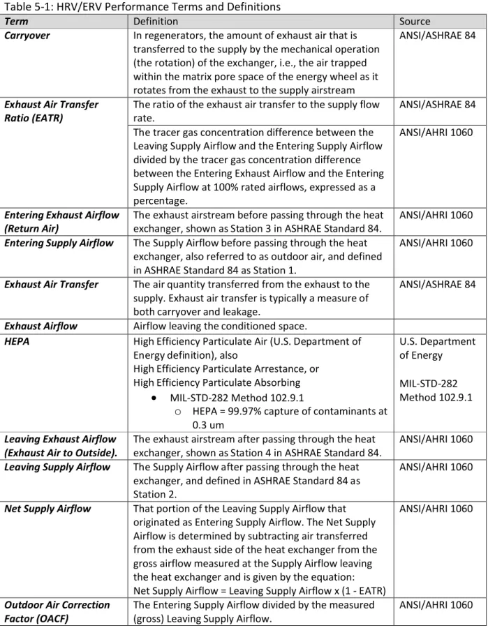
Table 5-1: HRV/ERV Performance Terms and Definitions
Term Definition Source
Carryover In regenerators, the amount of exhaust air that is transferred to the supply by the mechanical operation (the rotation) of the exchanger, i.e., the air trapped within the matrix pore space of the energy wheel as it rotates from the exhaust to the supply airstream
ANSI/ASHRAE 84
Exhaust Air Transfer
Ratio (EATR) The ratio of the exhaust air transfer to the supply flow rate. ANSI/ASHRAE 84 The tracer gas concentration difference between the
Leaving Supply Airflow and the Entering Supply Airflow divided by the tracer gas concentration difference between the Entering Exhaust Airflow and the Entering Supply Airflow at 100% rated airflows, expressed as a percentage.
ANSI/AHRI 1060
Entering Exhaust Airflow
(Return Air) The exhaust airstream before passing through the heat exchanger, shown as Station 3 in ASHRAE Standard 84. ANSI/AHRI 1060
Entering Supply Airflow The Supply Airflow before passing through the heat exchanger, also referred to as outdoor air, and defined in ASHRAE Standard 84 as Station 1.
ANSI/AHRI 1060
Exhaust Air Transfer The air quantity transferred from the exhaust to the supply. Exhaust air transfer is typically a measure of both carryover and leakage.
ANSI/ASHRAE 84
Exhaust Airflow Airflow leaving the conditioned space.
HEPA High Efficiency Particulate Air (U.S. Department of Energy definition), also
High Efficiency Particulate Arrestance, or High Efficiency Particulate Absorbing
MIL-STD-282 Method 102.9.1
o HEPA = 99.97% capture of contaminants at 0.3 um
U.S. Department of Energy
MIL-STD-282 Method 102.9.1
Leaving Exhaust Airflow
(Exhaust Air to Outside). The exhaust airstream after passing through the heatexchanger, shown as Station 4 in ASHRAE Standard 84. ANSI/AHRI 1060
Leaving Supply Airflow The Supply Airflow after passing through the heat exchanger, and defined in ASHRAE Standard 84 as Station 2.
ANSI/AHRI 1060
Net Supply Airflow That portion of the Leaving Supply Airflow that originated as Entering Supply Airflow. The Net Supply Airflow is determined by subtracting air transferred from the exhaust side of the heat exchanger from the gross airflow measured at the Supply Airflow leaving the heat exchanger and is given by the equation: Net Supply Airflow = Leaving Supply Airflow x (1 - EATR)
ANSI/AHRI 1060
Outdoor Air Correction
Term Definition Source The entering supply airflow divided by the leaving
supply airflow (= m1/ m2where m1and m2are the mass
flow rates of dry air at Stations 1 – Supply Inlet and 2 – Supply Outlet).
ANSI/ASHRAE 84
Recovery Efficiency Ratio
(RER) Ratio of the energy recovered divided by the energy expended in the energy recovery process. ANSI/ASHRAE 84
Standard air Dry air at 21°C and 101.325 kPa absolute. Under these
conditions dry air has a mass density of 1.204 kg/m3. ANSI/ASHRAE 84 Supply Airflow. The outdoor airflow, also referred to as rated airflow. ANSI/AHRI 1060
5.3 Other Abbreviations
CAS# Chemical Abstracts Service registration number
cfm cubic feet per minute
DNPH 2,4-Dinitrophenylhydrazine
GC/MS gas chromatograph/mass spectrometer
HPLC high performance liquid chromatography
L litres
L/s litres per second
ng nanograms
NIST National Institute of Standards and Technology
Pa Pascals
PM particulate matter
ppb parts per billion
ppm parts per million
RT retention time
s seconds
TVOC Total volatile organic compounds
UV ultra-violet
wg inch of water gauge
6 PROTOCOL
6.1 Overview of Test Methods:
The TAC recommended testing the initial (new system) performance of HRV/ERV systems in four key areas:
Volumetric Flow Rates: Confirmation of specified volumetric flow rates of the installed system (Test 1).
Complete System Emissions: By-product (ozone) and organic compounds emissions of the installed complete system (Tests 2a and 2b).
Particle Filtration: Removal efficiency performance of the installed system (Test 3).
System Component Emissions: Organic compound emissions of individual HRV/ERV System components (headspace chamber tests of system components if results from Test 2b indicate the presence of a contaminant source from the system) (Test 4).
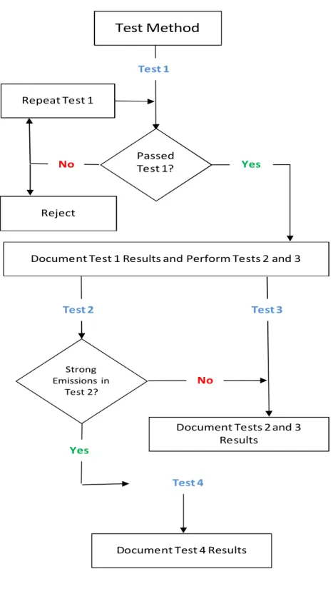
Figure 6-1 illustrates the flow chart of the test method.
Test 1 simply verifies that the UUT is providing the specified flow rates under standard conditions (as claimed by the manufacturer and / or certified by independent test agencies). It also provides an initial flush-out or conditioning period for the UUT. Test 1 is a Pass / Fail based on UUT age and flow performance criteria that shall be passed before IAQ performance testing (Tests 2, 3 and 4) is initiated.
Tests 1 to 3 are considered “core” IAQ performance tests that shall be completed on fully assembled operational HRV/ERV systems.
Test 4, examining component emissions, is required only if the results from Test 2 indicate presence of strong (a “Fail” in the evaluation criteria given in this protocol) organic compound source or sources that individual component testing will help to identify for corrective action or product improvement/retesting.
For Tests 1, 2 and 3, any flexible ductwork specified by the manufacturer is included in the UUT system. A standard bench top test rig based on an existing standard - CAN/CSA-C439 has been developed for this purpose (Section 7). However, due to the wide range of specific system components, design features and operational modes available for any particular HRV / ERV system, the precise steps required for Tests 2 and 3 may depend on the particular HRV/ERV system under test. Examples include systems that incorporate enhanced filtration systems (gas-phase or particulate) and / or flow pathways that can switch to partial or full recirculation modes depending on user-defined setpoints and / or periodic cycles that may or may not depend on outdoor air temperature, or responses from optionally humidity or sensors that crudely measure IAQ.
Tests 2 and 3 must be conducted on a new system shipped directly from the manufacturing site in order to determine initial performance and IAQ impact.
Figure 6-1: Flow chart of the test method
Passed Test 1?
No Yes
Document Test 1 Results and Perform Tests 2 and 3
Document Tests 2 and 3 Results
Yes
No
Document Test 4 Results Repeat Test 1 Test 2 Strong Emissions in Test 2? Test 3 Reject Test 1 Test 4
Test Method
7 FACILITIES AND INSTRUMENTS FOR DETERMINING PERFORMANCE
7.1 HRV System / Ductwork Test Platform
The basic test rig used for Tests 1, 2 and 3 consists of four sets of ductwork segments to which the UUT can be connected to simulate basic operation of the installed system. It is similar to the test rig used by CAN/CSA C439 (Figure 7-1) with the following modifications:
temperature and humidity conditioning of the inlet air streams to the UUT (to support thermal or humidity exchange efficiency monitoring) are not required, instead lab air may be used providing specified T/RH ranges are met,
the test rig does not consist of recirculation loops, but features instead straight, single pass sections, and
The test rig differs from the C439 apparatus in providing ports specifically designed for air sampling analysis and for injection of particulate matter challenges (used in Tests 2 and 3).
Figure 7-1: Source CSA C439
The system should be designed and constructed following the guidance provided in ASHRAE Fundamentals, including the positions of all flow and pressure sensing devices and the need for flow straighteners in the ductwork assemblies. Additional information specific for the design and location of flow sensing devices can be found in ASHRAE 41.2. Since Test 3 involves the injection of particles in the outdoor and return air duct segments, the supply air from the HRV/ERV system should be vented outside the occupied lab space.
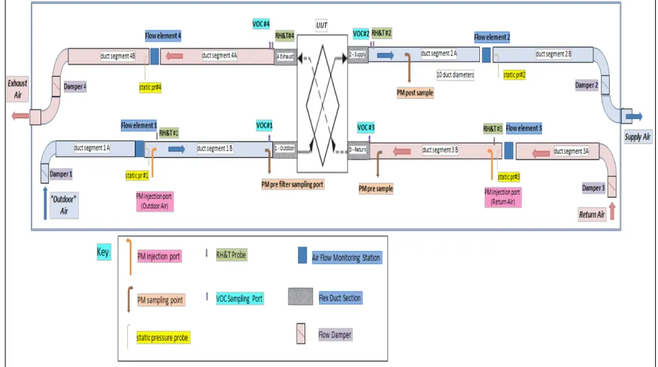
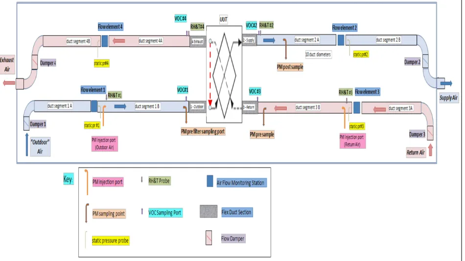
The schematic for the HRV/ERV system test rig required to meet the requirements for Tests 1, 2 and 3 is shown in Figure 7-2. An example of an actual installation of the HRV/ERV system test rig is shown in Figure 7-3.
Figure 7-3: Example of an actual installation of the HRV/ERV system test rig.
As indicated in Figure 7-2, “Outdoor” air can be room (or lab) air with a temperature of 23 ± 1oC and a
relative humidity of 40 ± 15%. The temperature and relative humidity conditions are established to not adversely impact the organic compound background requirements for Test 2. This does not mean that true outdoor air cannot be used and appropriately conditioned if preferred, provided that the temperature and humidity conditioning systems employed can provide an inlet air temperature of 23 ± 1oC and relative humidity of 40 ± 15%. The supply air from the UUT is exhausted to the
outdoors since the particulate matter (PM) levels in the supply air stream may become elevated during Test 3 which requires the generation and injection of fine particulate matter into the outdoor and return air duct segments.
The facility (as indicated by the blue outline in Figure 7-2) housing the HRV/ERV system test rig, must have sufficient air exchange to compensate for the impact of UUT’s operation. In the setup shown, both the outdoor and return air flows are obtained from the lab space (as exhaust and supply air streams). Sufficient air exchange has to be supplied to avoid depressurization of the facility. During operation of the UUT, a maximum pressure difference between outdoor and indoor must not exceed 10Pa.
As an alternative arrangement, it is acceptable to install HEPA filtration in the supply air section downstream of the test sections. In this case, the setup would likely require installation of a blower unit downstream of the HEPA filter that would compensate for the HEPA’s air flow resistance and enable balanced airflow delivery within the UUT.
7.2 Requirements for Ductwork and Test Parameter Monitoring Stations
The ductwork used in the construction of the test rig shall be rigid sections with a minimum internal diameter of 15.2 mm (6 inches). Spiral duct is acceptable if the joints are well-sealed to prevent leakage. Galvanized ducting is adequate, provided it is carefully cleaned with laboratory grade detergent (for example detergent used for glass cleaning) and rinsed with clean water to remove any residual oils from the manufacturing process. Each of the four duct sections shall be fitted with air flow rate monitoring equipment, air temperature and relative humidity sensing, as well as ports for air sampling. Principles outlined in ASHRAE Fundamentals should be followed regarding the design and positioning of these air flow sensors and controls. As indicated in Figure 7-2, the termination of each duct section is fitted with a damper that can be used for flow balancing as necessary. Additionally, the dampers in the “supply” and “exhaust” sections can be fully closed when the facility is not in use to block flow of outdoor air into the test apparatus.
The design and naming convention used for identifying these duct segments shall conform to the station identification established in both ASHRAE Standard 84 – Method of Testing Air-to-Air Heat/Energy Exchangers and CAN/CSA-C439 Standard Laboratory Methods of Test for Rating the Performance of Heat/Energy Recovery Ventilators:
Station 1 = Supply Air Inlet = Outdoor Air Station 2 = Supply Air Outlet = Supply Air Station 3 = Exhaust Air Inlet = Return Air Station 4 = Exhaust Air Outlet = Exhaust Air
Environmental parameters and flow conditions at each monitoring station will be identified according to this naming convention, thus the air temperature at Station 2; Supply Air should be identified as T2. All sensors used for monitoring temperature, humidity, pressure and flow shall be calibrated at
manufacturer-recommended intervals or annually (whichever is less) to traceable standards. Calibration records shall be kept on file and available for review by the manufacturer of the UUT. Airflow rate, static pressure, temperature, and relative humidity shall be measured at each station according to the detailed guidance that follows. Air sampling and analysis requirements for organic compounds, ozone, and particulate matter will be described for the specific test methods (Tests 2 and 3) below.
7.3 Temperature and Relative Humidity
Temperature measurements in each measuring station shall be recorded using one of the following instruments:
a) Resistance Temperature Detectors (RTD), b) thermistors, or
c) thermocouples.
Temperature sensors shall be calibrated and traceable to NIST Standards and have an accuracy of least ± 0.5 oC.
Humidity at each measuring station shall be recorded using either dew point or relative humidity sensors. Sensors employed shall be calibrated and traceable to NIST Standards and have a minimum
The temperature and humidity sensors shall be mounted such that measurements are taken near the midpoint of the airstream at each monitoring station. Their location and design shall be such that flow rate monitoring at the station is not affected. Note that in duct segments 1 and 3, Outdoor and Return Air, respectively, the temperature and humidity sensors shall be located upstream of the Particulate Matter injection position to prevent fouling of the temperature and humidity probes during the particle injection challenges for Test 3.
7.4 Static and Differential Pressure
Duct static pressures shall be monitored using probes following ASHRAE Standard 41.2 - Standard Methods for Laboratory Air-Flow Measurement. If surface mount static pressure probes are used, care must be taken to ensure that the inner duct surfaces are free of irregularities including burrs, and that probes are installed so as to accurately measure static pressure at each monitoring station. Pressure transducers used to monitor the system static and differential pressures should be selected (range and precision) to provide a minimum accuracy of ± 1% of reading.
7.5 Volumetric Air Flow Rates
Volumetric Air Flow rates (L/s) shall be measured according to the requirements of ASHRAE Standard 41.2-1987 (R1992) - Standard Methods for Laboratory Airflow Measurement and ANSI/AMCA 210-2007 - ANSI/ASHRAE Standard 51-07 - Laboratory Methods of Testing Fans for Certified Aerodynamic Performance Rating. Where commercially available flow monitoring devices are used, the units must be sized appropriately according to the anticipated flow ranges of the UUT (typically between 25 and 200 L/s, or 53 to 424 cfm per National Building Code of Canada, NBC Article 6.2.1.6), and have a minimum cumulative accuracy (including error associated with any pressure sensing devices used to determine flow rates) of 5% or 5 L/s, whichever is smaller. The flow monitoring devices must be calibrated prior to use (at manufacturer-recommended intervals, or annual, whichever is less). Acceptable flow monitoring devices include averaging or pitot tube arrays installed and tested according to guidance provided by ASTM D3154-00(2006) Standard Test Method for Average Velocity in a Duct (Pitot Tube Method), flow nozzles, and venturi tubes. Laminar flow elements or orifice plates should only be used in combination with supplemental balancing fans to prevent pressurization (positive or negative) of the UUT flow pathways. Note that particle injection ports in the outdoor and return air duct sections should be located downstream of the flow monitoring stations.
7.6 Data Acquisition System (DAS)
A DAS system shall be installed to automatically record all test parameters and conditions at the levels of accuracy and precisions outlined above. Sampling frequency of the DAS shall be sufficient to provide data at 15 second increments at minimum. A point-to-point inspection must be conducted to check electrical connections to all sensors, confirm that locations are properly identified and logged, and to confirm correct sensor response must be conducted. DAS readings are to be verified using handheld monitors that are calibrated to traceable standards. Reported values are to be converted to measured parameters using calibration curves developed for individual sensors. Sensors used for the DAS (temperature, RH, volumetric flow rate, static pressure, differential pressures) shall be regularly maintained and calibrated as described in greater detail above.
7.7 Ozone Monitors
Ozone monitors employed in this test should meet the requirements of UL867 and have a limit of detection of 2 ppb ozone at minimum and an accuracy of +/- 2% of reading. Chemiluminescence and UV-based detectors are suitable. All air sampling lines connected to the ozone detector should be made of Teflon (PTFE). Sample results should be logged internally by the device or recorded using a separate DAS at a minimum sampling interval of 15 s. Paired analyzers (identical in design and sampling flow rate) should be used in order to conduct simultaneous upstream / downstream air sampling. The use of a single ozone monitor and a valve to sample upstream and downstream air sequentially is not recommended6.
7.8 Air sampling of VOCs in outdoor, exhaust, return and supply air
Air sampling from the test rig ductwork shall be conducted according to guidelines provided in ASTM D6196. Selection of appropriate sampling media (sorbent tubes) shall be in accordance to ASTM D6345 where multisorbent tubes are recommended.
Sample analysis techniques shall be consistent with the objective of determining the identity and concentrations of individual volatile organic compounds (VOCs) present in the collected air samples. For this purpose, GC/MS analysis is recommended. The selected sampling and analytical methods should have sufficient sensitivity and accuracy to provide a detection limit of 2 μg m-3for individual VOCs.
Air sampling pumps and controllers should be capable of accurately determining sampling volumes using the selected sorbent tubes within 5%.
7.9 Air sampling of carbonyl compounds in outdoor, exhaust, return and supply air
Air sampling from the test rig ductwork shall be conducted according to guidelines provided in ASTM D5197.
Sample analysis techniques shall be consistent with the objective of determining the identities and concentrations of individual carbonyl compounds (e.g. formaldehyde) present in the collected air samples. For this purpose, HPLC analysis of DNPH derivatives following the ASTM 5197 procedure is recommended. The selected sampling and analytical methods should have sufficient sensitivity and accuracy to provide a detection limit of 2 μg m-3for individual carbonyl compounds.
Air sampling pumps and controllers should be capable of accurately determining sampling volumes using the selected sorbent tubes within 5%.
7.10 Particle Generation System
A particle generation system capable of aerosolizing Arizona Test Dust, ISO-12103-1, A2 (Fine Test Dust) shall be used for this protocol. The PM Injection nozzles are to be installed in duct segment 1 (Outdoor Air) and segment 3 (Return Air) if UUT is equipped with recirculation mode operation capability (refer to Figure 7-5). Note, as indicated in the figure, that these nozzles must be installed downstream of the RH&T sensors to prevent fouling.
7.11 Particulate Matter Sampling and Analysis
Optical particle counters (OPC) capable of detecting discrete size classes of suspended particulates at minimum PM2.5and PM10levels shall be used. If enhanced filtration capabilities are claimed by the UUT,
then the particle monitoring equipment must be capable of monitoring at the specified performance level. Paired OPCs are required in order to perform simultaneous upstream / downstream monitoring. The paired OPCs shall be identical in design and sampling flow rate7.
Isokinetic sampling heads mounted in duct segments 1 and 2 (and 3 if UUT has recirculation mode) are to be used as identified in Figure 7-5. The inlet nozzles of upstream and downstream sample isokinetic probes shall be sharp edged and of appropriate entrance diameter to maintain isokinetic sampling within 10% at the test airflow rate
7.12 Small Emission Chamber
Small emissions chamber (typical internal volume ~50L), although a larger chamber (~ 1 m3) may be
required to accommodate larger HRV / ERV components such as core assemblies. The chamber should be constructed and operated according to guidelines provided in ASTM D 5116. Chamber environmental conditions shall be set at 30oC ± 1oCand 50% RH ± 5%. An example chamber system is showed below.
Figure 7-4: Small chamber system for headspace analysis of component emissions.
7 Particle concentrations agreement between paired OPCs can be determined by conducting side-by-side
measurements. Paired OPCs are considered in agreement if plots of their concentrations revealed a regression line of slope equal to 1 (± 0.1) and a y-intercept of 0 (± 0.1).
8 TEST METHODS
8.1 Descriptions of Unit Under Test (UUT) and Test Agency
The test report shall include a detailed description of the unit under test including the product description, manufacturing history (site and date), rated airflow performance, operation mode(s), IAQ related claims, certificates of performance, filter documentation (if any) and photographs of the test unit. Complete all required information using the forms provided in Section 9.1.
8.2 Test 1 – System Flow Rates
8.2.1 Intent:
This test is to verify, prior to IAQ impact assessment testing, that the UUT is operating per manufacturer-specified flow rates under standard conditions (and as certified by independent test agencies). Testing should be performed consistent with CAN/CSA-C439-09 Section 8.1: Airflow rate measurement procedure (which cites ANSI/AMCA 210 - ANSI/ASHRAE Standard 51-07).
Test 1 also serves to provide an opportunity to observe the UUT in operation and determine the characteristics of its various operation modes. The timing and impact of these modes on the flow paths and delivered volumetric flow rates in each airstream must be identified and noted as they may affect the successful operation of subsequent tests (an example of this being the timing or frequency of any automatic switchovers to recirculation modes and/or automated changes in fan speed operation).
Test 1 is a Pass / Fail stage that must be satisfied before IAQ performance testing (Tests 2, 3 and 4) should be initiated.
While Test 1 provides an initial flush out / conditioning period for the UUT, the total operational time during Test 1 should not exceed 48 hours. During this time period (and during Tests 2 and 3) it is important that background conditions (lab air if test rig configured such that lab air is used as “outdoor”air) be maintained such that UUT contamination does not occur. In practise, this requires that background TVOC and PM10 levels not exceed 250 µg/m3and 50 µg/m3respectively.
8.2.2 Test Procedure – System Flow Rates
The HRV/ERV system under test shall be connected to the test rig in accordance with the manufacturer’s installation recommendations to the extent possible. This includes the use of manufacturer-supplied or recommended fittings and flexible ductwork (minimum lengths: 2m /section) for making connections to outdoor air intake, exhaust air discharge and supply and return air positions.
Once the unit is fully installed and all connections carefully sealed according to manufacturer instruction, all dampers in the duct sections shall be fully opened (Dampers 1 through 4 in Figure 7-2).
Test Conditions:
Supply Air Flowrate (Q2): 100% of the rated airflow of the UUT
Return Air Flowrate (Q3): same as Supply Air Flowrate (Q2= Q3)
Therefore, the pressure difference between Supply (Ps2) and Return (Ps3) should be 0 according to
Section 8.2.3.
The unit under test shall then be turned on to its normal flow condition and flows shall be recorded at all four measuring stations simultaneously. As necessary, adjust dampers 1-4 in order to achieve balanced flow conditions within 90% as specified in CAN/CSA F326-M91 (R2010). Note, that some HRV/ERV systems may be supplied with balancing damper systems. In this case, install the system with the dampers in place and balance according to manufacturer’s guidelines. Once the UUT has been balanced, record flow values from all four measuring stations and compare to UUT specifications provided by the manufacturer, or by an independent certification body, if applicable. Set HRV operation to maximum air flow and observe flow readings for a minimum of 1 hour at the 4 stations. Repeat this procedure for any additional operation modes for the UUT.
With HRV set to operate in its normal mode, record flow conditions for a minimum of 1 hour at the 4 stations. Note especially the occurrence, timing and duration of any step changes in flow, e.g. resulting from default programming shifts in HRV operation. It may be necessary to override any flow shifts. If this is not possible, note the timing of their occurrence and adjust the testing procedure accordingly.
8.2.3 Data Analysis and Reporting
Record specified and observed flow rates using the tables found in Section 9.2 - Evaluation Test Reports.
Evaluation Criteria:
CSA F326 Section 8.13.3 (d), specifies that:
“the supply and exhaust airflow rates of heat recovery ventilators in the normal ventilation mode shall be balanced so that the value of the lesser flow shall be at least 90% of the value of the greater flow, unless otherwise recommended by the manufacturer”.
Test 1 PASS/FAIL based on:
a) The measured flows for the UUT were within 10% of their specified values, and
8.3 Test 2a: Ozone Emissions of the Complete System
8.3.1 Intent:
This test is to verify that fan motors or any supplemental particulate matter air purification device (e.g. electronic filters such as ionizers or electrostatic devices) installed in the HRV/ERV system will not generate ozone in significant amounts during operation. This test requires that ozone monitoring upstream and downstream of the HRV/ERV system be conducted.
If the UUT incorporates supplemental electronic filtration device(s), then this test should be conducted in 2 stages:
1) with the filtration system turned off (to check for possible ozone production by the HRV/ERV blower motors); and
2) with any supplemental filtration system turned on to test for ozone formation as a by-product of filter operation.
8.3.2 Test Procedure Ozone sampling:
Turn on the two ozone monitors and position them so that both are sampling from the same room air location. Allow the monitors to warm up for the period recommended by the manufacturer, and then confirm that both units are recording the same background ozone concentration (+/- 2 ppb).
Connect the PTFE air sampling lines from the two ozone monitors to the sampling ports at Stations 1 (Outdoor Air) and 2 (Supply Air)
Operate the HRV/ERV system at its highest flow setting in its normal mode of operation and record ozone levels for a minimum of 10 minutes at a minimum sampling interval of 15 s. Plot recorded data and calculate average values and standard deviations for both upstream
and downstream locations. 8.3.3 Data Analysis and Reporting
Record ozone concentrations and its net change using the tables found in Section 9.2 - Evaluation Test Reports.
Evaluation Criteria:
o The net increase in ozone levels (based on the difference of the average values obtained in the Outdoor Air and Supply Air streams (Stations 1 and 2) should be below the Health Canada recommended residential IAQ guideline for ozone of 20 ppb8.
Pass: net change in ozone level < 20 ppb Fail: net change in ozone level ≥ 20 ppb
8Even though device emissions are below the guideline levels set out in this protocol, certain conditions (high
outdoor ozone, other indoor sources) may cumulatively increase the concentrations above threshold guidelines when installed in residences. Under such conditions, it is recommended that appropriate mitigation measures such as indoor source removal and turning off the HRV/ERV unit during periods of high outdoor ozone levels be taken.
8.4 Tests 2b and 2c: Volatile Organic Compound Emissions of the Complete System:
8.4.1 Intent:
This test is to verify that HRV/ERV system (including supplied/recommended flexible ductwork and connections) does not act as a source of volatile organic or carbonyl compounds. The test is performed by conducting air sampling from the Outdoor Air upstream of the HRV /ERV system (Station 1) and immediately downstream in the Supply Air duct (Station 2). Any observed increases in contaminant levels will be attributed to the HRV/ERV system, and compared to guideline values for specific contaminants. If the HRV/ERV system provides a recirculation mode of operation, then the test should be repeated with the system set to operate in the recirculation mode, but with VOC/carbonyl sampling additionally being taken from the Return Air duct (Station 3).
8.4.2 Test Procedures:
8.4.2.1 Test 2b: Volatile Organic Compounds
Confirm that total operational time of UUT during Tests 1 and 2a has not exceeded 48 h.
If lab air is used as Outdoor Air for UUT, collect a lab air sample and confirm that VOC background levels are acceptable (TVOC < 250 µg/m3).
To confirm that the test rig ductwork is not a source of VOC contamination, with the UUT operating under the desired test conditions, collect simultaneous 2L air samples (e.g. 20 min at 100 mL/min) from the outdoor air (or lab air depending on system configuration) and from within the Outdoor Air duct segment (Segment 1) at test location “VOC#1” identified in Figure 7-2. Compare these results. If elevation in any contaminant is observed, identify source and resolve (re-clean ductwork if necessary).
With the UUT in stable operation under “Normal” conditions (allow 30 minutes for system to stabilize, flows must be maintained +/- 10% of Test 1 conditions), simultaneously collect air samples from points “VOC#1” (Outdoor Air) and “VOC#2” (Supply Air). Repeat so as to collect two paired sets of air samples.
Record start time and operational parameters of UUT. For all air samples, record the following:
Sample location (VOC#1,2,3,4,Outdoor or Lab) Sampling tube make/model/Serial Number Sampling system components (pump/controllers) Sampling rate (mL/min), (50 – 200 mL/min) Sampling start and stop time/date
Sampling personnel name
Discrete sample code (including Test ID and sample number)
Collect lab blank samples by briefly opening and closing clean sorbent tubes co-located with air sample tubes during UUT testing period.
If UUT possess an optional recirculation mode, repeat the above testing with simultaneous sampling at locations “VOC#2” (Supply Air) and “VOC#3” (Return Air) identified in Figure 7-5.
8.4.2.2 Test 2c: Carbonyl Compounds
Coordinating with VOC sampling above, simultaneously collect 20 L air samples (e.g. 100 min at 200 mL/min) from points “VOC#1” (Outdoor Air) and “VOC#2” (Supply Air). Repeat so as to collect two paired sets of air samples.
For all air samples of carbonyl compounds, record the following: Sample location (VOC#1,2,3,4,Outdoor or Lab)
Sampling tube make/model/Serial Number Sampling system components (pump/controllers) Sampling rate (mL/min), (50 – 200 mL/min) Sampling start and stop time/date
Sampling personnel name
Discrete sample code (including Test ID and sample number)
Collect lab blank samples by briefly opening and closing clean cartridges co-located with air sample tubes during UUT testing period.
If UUT possess an optional recirculation mode, repeat the above testing with simultaneous sampling at locations “VOC#2” (Supply Air) and “VOC#3” (Return Air) identified in Figure 7-5.
8.4.3 Data Analysis and Reporting
Describe in detail the air sampling equipment used (pumps, flow controllers, timing devices, sample collection media and its handling/preparation including cleaning).
Describe the analytical systems used for VOC and carbonyl sample analysis (including analytical instrumentation, analysis conditions, calibration, and integration parameters)
Test 2b: For VOC samples
Reported blank - corrected values expressed as µg/m3:
(VOC mass on sample tube – mass in blank tube) / sample volume
Report limit of detection, LOD, (µg/m3: assume a 2L sample) for each VOC detected.
Report values using the tables provided in Section 9.2.2.2 (Report VOC levels only for those compounds that exceed LOD)
Test 2c: For carbonyl compound samples:
Reported blank - corrected values expressed as µg/m3:
(carbonyl compound mass on sample cartridge – mass in blank cartridge) / sample volume Report limit of detection, LOD, (µg/m3: assume a 2L sample) for each compound detected.
Report values using the tables provided in Section 9.2.2.3 (Report VOC levels only for those compounds that exceed LOD)
8.5 Test 3: Particle Filtration by the Complete System:
8.5.1 Intent:
The intent of this test is to determine the installed performance of basic and any supplemental/ enhanced particle filtration systems present in the UUT (using a single pass approach)9. Any by-pass
leakage that may be occurring due to improperly designed/sealed flow paths within the particular UUT and/or any weaknesses in filter mounts/seals can be determined by evaluating the in-situ PM removal performance of the installed unit.
The test requires evaluation of both PM2.5and PM10levels and removal performance.
The following table summarizes possible enhanced filtration capabilities in the UUT. Table 8-1: Possible enhanced filtration capabilities in the UUT
System Component Performance Claim Test Requirement Enhanced Particle Filtration Improved removal of outdoor
PM via HEPA or Electrostatic Precipitation
Dose outdoor air stream with particulates and sample supply air Enhanced Particle Filtration:
Recirculation Mode Operation Reduce indoor particulate levels due to recirculation filtration Dose return air stream with particulates and sample supply air 8.5.2 Test Procedure:
Verify that all filters, filter cartridges and frames are oriented correctly and mounted within the unit per manufacturer’s instructions.
Ensure that date/time values in both DAS and OPCs are synchronized.
If lab air is used as Outdoor Air for UUT, collect a lab air sample and confirm that PM10background levels
are acceptable (PM10< 50 µg/m3).
Operate the UUT in normal mode and record all flowrates, temperatures and relative humidity in each test section via DAS. Allow sufficient time to confirm that all flows are stable within +/- 10% of Test 1 conditions.
Use correct isokinetic sampling heads for sampling particulate based on UUT flowrates. Sample suspended particulate levels in Outdoor and Supply Air duct segments and record background levels. Commence injection of PM (refer to Section 7.1) in Outdoor Air section and continue injection until stable levels of approximately 100 µg/m3(± 10%) have been maintained in the Outdoor Air duct for 10
to 15 minutes.
Discontinue PM dosing while continuing to sample for a further 5 to 10 minutes. 8.5.3 Data Analysis and Reporting
Document all filters supplied with system, including any pre-filter systems. Record all make/model information as well as any specified performance values.
Record system flows, temperatures and RH values for all duct sections using the DAS.
Plot observed PM levels and calculate mean levels and standard deviations before, during and after PM injection.
Use tables provided in Section 9.2.3 to record PM removal performance.
8.6 Test 4: Organic Compound Emissions of the System Components (Headspace Chambers):
8.6.1 Intent:
Test 4 is an optional test intended to allow the manufacturer to identify the specific cause of a failure of Test 2b or 2c. It involves “headspace” emissions testing of individual HRV / ERV system components in “small” environmental chambers. General guidelines from ASTM D5116 shall be followed.
The selection of specific system component (s) to be tested will be based on evaluation of Test 2b and 2c results, discussion with the HRV/ERV system manufacturer and component supplier if necessary, and may include one or more of the following:
o HRV / ERV core materials (including polypropylene / polypropylene copolymers, aluminum, stainless steel, polymer membranes).
o Flexible ducting materials and connectors (including vinyl compounds, aluminum foils, polyester laminates, metalized polyester films).
o Outdoor air intake materials. o Motor / blower systems.
o Filtration devices (filter beds, basic Polyester air filters, pleated filters, supports, gaskets). o Cabinet materials (metal, plastics).
o Sound deadening materials used in cabinet, including foamed plastics. o Optional balancing dampers.
If the source of the contaminant is clearly identified by headspace test (s), then substitution by the system supplier of the component responsible for the “Fail” can precede a re-test of the complete system (Figure 8-1).
Figure 8-1: Decision process/follow-up for implementing Test 4. 8.6.2 Test Procedure
Set chamber operation conditions to 30oC via environment enclosure or lab space environmental
controls.
Clean the chamber using laboratory grade glassware detergent in water. Rinse with tap water then distilled water and dry using clean cloths. Flush with clean air (50% RH) until humidity of exhaust air is stable at 50% RH +/- 5%.
Collect background air sample using techniques described in Tests 2b and2c and analyze on GC/MS and HPLC to confirm chamber background meets following criteria :
TVOC: ≤ 10 μg/m3
Individual compounds, including Formaldehyde: ≤ 2 μg/m3
If chamber background acceptable, load UUT component into chamber and reseal. Flush chamber for 3 h at 1 air change/h using 50% RH supply air. Discontinue flushing and seal chamber. Maintain chamber temperature at 30oC. After 24 h, reconnect chamber supply air and flush at 250 mL/min. Using a vented
T-fitting at the chamber exhaust, immediately begin air sampling from the exhaust air at 200 mL/min. Collect VOC sample first (approx. 2L) followed by carbonyl compound sample (approx. 10L).
If background chamber is not acceptable, re-clean.
Analytical and air sampling equipments required for the headspace testing are identical to those described for Tests 2b and 2c.
8.6.3 Data Analysis and Reporting:
Describe and record any identification markings on tested component (s), including: manufacturer/make/model/serial numbers
compositions
specifications listed for any filter materials date of manufacture
Report chamber background test results.
9 TEST REPORT
The test report shall include the following information:
9.1 Description of UUT / Test Agency:
The test report shall contain the following information: o Make / Model / Serial Number
o Manufacturing Date and site
o 3rdparty certification that UUT is representative of product
o Date received by test lab o Rated airflow delivery rates:
o Operation Modes provided by the system
o Document any IAQ-related claims made for the UUT
o Certificates of performance – record information from any certificates attached or supplied with the UUT o Document all filters supplied with system (or installed as optional components for the purpose of the test):
include descriptions of filter sizes, types, frame/holder construction, claimed performance specifications o Document make / model / manufacturer information of all flexible ducting supplied with or recommended
for use during installation
a) UUT Description: Make: ________________________________ Model: ________________________________ Serial Number: ________________________________ Manufacture Site: ________________________________ Date of Manufacture: ________________________________ Specified Flows by Manufacturer:
____ cfm (___ L/s) @ ___in wg (___ Pa) ____ cfm (___ L/s) @ ___in wg (___ Pa)
Rated Air Flows (per certification label):
Certification Source: ________________________________ Certified flows: o ____ cfm (___ L/s) @ ___in wg (___ Pa) o ____ cfm (___ L/s) @ ___in wg (___ Pa) Modes of Operation: ________________________________ ________________________________ ________________________________ ________________________________
Filtration Components Installed in System:
________________________________ ________________________________ ________________________________
Supplied Installation Components:
Flexible Ducting:
o Outdoor / Exhaust Air:
Make/Model: ________________________________ Installed Length: ______________________________ o Supply / Return Air:
Make/Model: ________________________________ Installed Length: ______________________________
IAQ-related performance claims from Manufacturer’s advertising/operational literature:
________________________________ ________________________________ ________________________________ ________________________________
b) Test Lab / UUT Collection and Test Details:
Lab Name and Location: ________________________________ Contact Name: ________________________________
UUT collection details:
Obtained from: ________________________________ Date Obtained: ________________________________ Condition on Receipt: ________________________________
Internal Test Code: ________________________________ Test Dates: ________________________________
UUT acceptable for Testing?
UUT age at test date: ____________ days
9.2 Evaluation Test Reports:
9.2.1 Test 1 Report: System air flows: Table 9-1: Observed UUT Flows – Normal Mode
Flow Section Normal Mode
Specification (L/s) Observed (L/s) Date/Time Agreement, % Station 1: Outdoor Air
Station 2: Supply Air Station 3: Return Air Station 4: Exhaust Air
Table 9-2: Observed UUT Flows – Maximum Mode
Flow Section Max Mode
Specification (L/s) Observed (L/s) Date/Time Agreement, % Station 1: Outdoor Air
Station 2: Supply Air Station 3: Return Air Station 4: Exhaust Air
Table 9-3: Observed UUT Flows – Recirculation Mode
Flow Section Recirculation Mode (if available) Specification (L/s) Observed (L/s) Date/Time Agreement, % Station 1: Outdoor Air
Station 2: Supply Air Station 3: Return Air Station 4: Exhaust Air
Normal mode meets CSA F326 requirement for Supply = Exhaust within 10%?: calculated difference: _______________ %
9.2.2 Test 2 Report: Organic Compound Emissions from System: 9.2.2.1 Test 2a - By-product Ozone generation:
a) Normal mode:
Table 9-4: Ozone generation in the UUT - Normal Mode O3Level in Outdoor Air
(Station 1), ppb O(Station 2), ppb3Level in Supply Air Net change in O3level, ppb Test Result:
Supply air Ozone (Normal Mode): Net change < 20 ppb: (Pass/ Fail): ____________
b) Recirculation mode (if available):
a. Applies to this UUT? (Yes/ No): ___________ Table 9-5: Ozone generation in the UUT - Recirculation Mode
O3Level in Return Air
(Station 3), ppb O(Station 2), ppb3Level in Supply Air Net change in O3level, ppb Test Result:
Supply air Ozone (Recirculation Mode): Net change < 20 ppb (Pass/ Fail / Not Applicable): __________ c) Ozone levels during use of supplemental filtration (if available):
a. Applies to this UUT? _______ (Yes/ No)
b. If yes: Nature of supplemental filtration? ____________ (electrostatic precipitator, …) Table 9-6: Ozone generation in the UUT during use of supplemental filtration
O3Level in Outdoor Air
(Station 1), ppb O(Station 2), ppb3Level in Supply Air Net change in O3level, ppb Test Result:
9.2.2.2 Test 2b Report: VOC Emissions – Full System:
Normal operation mode:
Report detected compounds (> LOD) using the following Table 9-7 and adapt classes and number of rows as needed.
Table 9-7: VOC emissions in the UUT – Normal Mode
Evaluation Criteria:
Pass: net level change is below all recommended guideline values listed in Table 10-3: or other criteria for acceptance
Marginal pass: ≤ 5 guideline values are exceeded, with none by a factor of more than 2 Fail: > 5 guideline values in Table 10-3 are exceeded by a factor of 2 or more
Test Result: (Pass/ Marginal Pass/Fail)
Note: Emitted compounds not listed in Table 10-3, but detected at levels exceeding 100 µg/m3, should be
reviewed by a qualified toxicologist. If determined to be a health concern, then the compound must be identified as such in the evaluation report and a “Fail” assigned under organic compound emissions.
Recirculation operation mode (if available):
Report detected compounds (> LOD) using the following Table 9-8 and adapt classes and number of rows as needed.
Table 9-8: VOC emissions in the UUT – Recirculation Mode
Evaluation Criteria:
Pass: net level change is below all recommended guideline values listed in Table 10-3: or other criteria for acceptance
Marginal pass: ≤ 5 guideline values are exceeded, with none by a factor of more than 2 Fail: > 5 guideline values in Table 10-3 are exceeded by a factor of 2 or more
Test Result: (Pass/ Marginal Pass/Fail)
Note: Emitted compounds not listed in Table 10-3, but detected at levels exceeding 100 µg/m3, should be
reviewed by a qualified toxicologist. If determined to be a health concern, then the compound must be identified as such in the evaluation report and a “Fail” assigned under organic compound emissions.