ASPECTS OF AUTOMATION MODE CONFUSION by Paul H. Wheeler University of B.S.E.E. Massachusetts at Amherst, 1988
SUBMITTED TO THE SYSTEM DESIGN AND MANAGEMENT PROGRAM IN PARTIAL FULFILLMENT OF THE REQUIREMENTS
FOR THE DEGREE OF
MASTER OF SCIENCE IN ENGINEERING AND MANAGEMENT AT THE
MASSACHUSETTS INSTITUTE OF TECHNOLOGY ( 2007 Paul H. Wheeler. All rights reserved.
The author hereby grants to MIT permission to reproduce and to distribute publicly paper and electronic copie5p f thi~sesis document in whole or in part in any mediupq now
o
or reafter createdSignature of the Author _
/f
Paul H. Wheeler System Design and Management Program May 11, 2007 Certified by:_
Professor of
Nancy G. Leveson Aeronautical and Astronautical Engineering Thesis supervisor Accepted by: MASSACHUSETTS INSTITUTE
I
OF TEOHNOLOOI
FEB 0 1
2008
Pat Hale Director, SDM ProgramBARKER
ASPECTS OF AUTOMATION MODE CONFUSION
by Paul H. Wheeler
Submitted to the System Design and Management Program on May 11, 2007 in Partial Fulfillment of the Requirements for the Degree of Master Science in Engineering and Management
ABSTRACT Complex systems such as commercial aircraft are difficult for
operators to manage. Designers, intending to simplify the interface between the operator and the system, have introduced automation to assist the operator. In most cases, the automation has helped the operator, but at times operator confusion as to what the automation is doing has created dangerous situations that lead to property damage or loss of life. This problem, known as mode confusion, has been difficult to analyze and thus solutions tend to be reactive instead of proactive. This thesis examines mode confusion as an emergent property of the operator and the automation. It develops models of the automation and the operator and then studies their emergent behavior. It then applies the model in a case study.
Thesis Supervisor: Nancy G. Leveson
TABLE OF CONTENTS
LIST O F FIG URES ... 7
INTRODUCTION ... 11
LITERATURE REvfEw ... 19
THE SYSTEM ... 27
THE OPERATOR ... 39
INTERACTIONS ... 53
CASE STUDY - ALARM CLOCK ... 67
APPLICATION OF A MODE CONFUSION FRAMEW ORK ... 89
CON CLU SION ... 97
LIST OF FIGURES
Number Page
Figure 1 Damage to Aeromexico Flight 945(Anonymous, 1980) ... 11
Figure 2 Kajaani Crash(Aircraft acddent at kajaani airport, finland, 3 november 1994, 19 96) ... 1 1 Figure 3 General Architectural View of System...28
Figure 4 Operational view of the system...28
Figure 5 Operator Controlling the System to deliver Value ... 30
Figure 6 System with Automation...33
Figure 7 System and Stateful Automation...34
Figure 8 The Operator in the System... 39
Figure 9 The Operator Delivering Value ... 40
Figure 10 The Trajectory of System States ... 41
Figure 11 A view of a Monolithic Task in the Context of a Higher Goal...42
Figure 12 Choosing What to do Next... 43
Figure 13 Many Ways to get to the Next State... 44
Figure 14 Individual Factors ... 45
Figure 15 Transforming Individuals to operators... 46
Figure 16 Methods of Norming... 46
Figure 17 Normed Operator Choosing Task and Goal...47
Figure 18- Intent of T asks...49
Figure 19 Intent of Subtasks... 49
Figure 20 Combined Operator and System Model...54
Figure 21 Operator Delegating a Task to Automation... 56
Figure 22 Delegating a Task to Automation...57
Figure 23 Operator Monitoring the Automation... 58
Figure 24 Goal Supporting Automation States... 60
Figure 25 Automation States with Operator Goals... 62
Figure 26 O perator G oals ... 63
Figure 27 The Author's Alarm Clock...67
Figure 28 Operator Interface... 68
Figure 29 The Clock in Off Mode...70
Figure 30 The Clock in Radio On Mode... 70
Figure 31 Modes and Indications Associated with Alarm "Auto" Mode ... 71
Figure 32 Set Time Interface State Machine...73
Figure 33 Active Alarm State Machine ... 75
ACKNOWLEDGMENTS
The author wishes to thank
Nancy Leveson for her support and tremendous patience
My son Tim, who has had limited father time over the last two years
And most importantly, my indefatigable wife Beth who has had to deal with my long absences and lack of funds
Chapter 1
INTRODUCTION
In 1979 at 29,800 ft, an Aeromexico DC-10 stalled over Luxembourg. While stalls in a small private airplane such as a Cessna 172 can be alarming when unexpected, it is not dangerous as long as the pilot is alert and the aircraft is high
Figure 1 Damage to Aeromexico Flight enough. In the case of the DC-10, 945(Anonymous, 1980) however there was significant damage
with approximately 4ft of control surface lost off its horizontal stabilizer (Figure 1). The subsequent accident report faulted the pilots for failing to follow proper climbout procedures.
More recently, an Air Libert6 Tunisie DC-9 overshot the runway while landing at Kajaani airport in Finland on November 3, 1994(Figure 2). The aircraft executed the final approach with too
much speed, resulting in the aircraft touching down 600 ft
beyond the normal
touchdown point. The
Finnish aviation authorities cited the crew for poor crew
resource management and
improper approach and Figure 2 Kajaani Crash(Aircraft accrdent at kajaani
braking technique
Even more recently, American Airlines flight 965 on approach to Cali, Columbia crashed into a mountain on December 20, 1995. In this case, the Cali crew set up their navigation equipment on the wrong fix causing the aircraft to follow a course into a mountain. The Columbian aviation authorities identified the crew as the probable cause of the accident (Cabrera et al., 1996)
In all of these incidents/accidents, the investigators cited the crews at fault for losing the situational awareness of operating the aircraft, but these accidents also have something else in common: Each of these accidents involved confusion with the flight management systems.
Designers intend automation systems to reduce the crew's workload by performing the mundane tasks associated with flying. Automation systems can be found on simple aircraft such as Cessna 172s and on more complex aircraft such as Douglas MD11s. For the Cessna 172, the automation provides for simple axis control and can aid in holding a course. This system is great for occasional pilots who are in the air and flying from point A to point B. For the MD1 1, the system is far more complicated. While it also controls the bank of the wings and direction of the aircraft, it also controls the thrust of the engines, the altitude of the aircraft, the speed of the aircraft, and more. Additionally these systems may provide for supervising the pilot in regard for safe flight. For example, Vakil (Vakil et al., 1996) describes the Airbus 320 automation that protects a plane from exceeding various airspeed limitations during flap deployment.
For all their complexity, these systems need to interface with the pilots. There are a number of tensions associated with this. First, there are limitations concerning space on an aircraft. When one examines the flight deck of an MD-11, one is
struck by the limited space. There is simply not enough room to put all of the instrumentation related to flight management at the hands of a single operator. Additionally there is a need for humans to monitor effectively the automation, and so an automation system that has a great deal of inputs and outputs would be very difficult to use. A designer needs to consider how to present enough information to the operator as to what the automation is doing without overwhelming him with lots of extra information.
An approach taken by automation designers to provide manageable interfaces is to multiplex the inputs and outputs. What this means is that depending on the current system mode, a particular interface presents itself to the user and to the
system. In this type of system, the automation has a number of modes and
depending on which mode is active the automation behaves in a particular way. For example, while in altitude capture mode, the automation will automatically (without interaction from the pilot) climb and level the aircraft at a particular altitude. This feature will not be enabled when the same automation system is in a vertical speed mode. In this case, the automation will control the aircraft's vertical speed (rate of climb) to the limits of the aircraft. These two automation modes provide very unique functionality yet share the same input/output interface to the pilot (Palmer, 1995; Rushby, 2002).
The weakness in this design is that the pilot must not only be situationally aware of the physical environment around her, she must be aware of the state of the
automation that controls the aircraft. Any misunderstanding of what the
automation is doing can cause dangerous confusions called mode confusions in the mind of the pilot.
Reexamining the accidents described earlier in this chapter, one can gain a sense of the problems of mode confusion. In the Aeromexico flight, the accident report speculated that the most likely scenario as to why the aircraft stalled was
that the autopilot system was set to a vertical speed mode and the auto throttle system was set to maintain an airspeed. This was different from the recollection of the aircrew, who recalled setting the autopilot to maintain an airspeed and the auto throttle to maintain a certain engine speed (Ni). The difference was that the former would create a situation where the aircraft would not maintain
performance as it gained altitude without pilot intervention. The report
speculates that the accidental toggling of a single dial might have led to the pilots thinking the automation was set to the other setting.
For the Kajaani crash, the situation was that while the aircraft was on final approach to the airport, the captain took the responsibility of flying the aircraft from the copilot. During this time, the report speculated that when the captain attempted to toggle off the auto throttle system, he accidentally toggled the
takeoff-go-around (TOGA) button. The effect of this was the automation
increased the power of the engines to maximum thrust. The captain physically reduced power using the throttles and disengaged the auto throttle system leading him to believe that the thrust was at idle when in fact it was not. These mistakes lead to the aircraft crossing the runway threshold 24 knots faster than normal and preventing the braking mechanism from deploying because the thrust was not at idle. The extra speed and poor braking caused the aircraft to slip off the runway. All of these accident reports were critical of the aircrews for losing situational awareness. Even so, the pilot is only one part of the overall system. The automation design plays a very important part of creating and maintaining that situational awareness and in each of these cases, the automation led the pilots into a trap. These reports recommend better training for the aircrews, but do not make recommendations as to fixing the inherent design flaws of the automation systems.
When one says there are inherent design flaws, one would expect that a designer should be able to do his job better. Unfortunately designers tend to view the operator in a somewhat dismissive way (Amalberti, 1998), as if the problems operators have with the automation are entirely the fault of the operators. The reality is that mode confusion is the result of the emergent behavior of the automation with the operator and thus to find mode confusion problems, one must have a model of both.
This thesis develops and proposes such a model. The model combines both an operator model and an automation model and examines the emergent behavior. The examination of this behavior can help identify mode confusion problems in
the system.
The contents of the thesis is as follows
Chapter 2 is a literature review examining the state of knowledge of mode confusion problems.
Chapter 3 deals with framing the mode confusion problem as a systems problem and develops the model of the automation.
Chapter 4 discusses and develops a model of the operator.
Chapter 5 examines the emergent behavior of the operator model and the system model.
Chapter 6 utilizes the model developed in chapters 3-5 in a case study
Chapter 7 applies the model to a general framework for mode confusion
Chapter 1 Endnotes
Aircraft accident at kajaani airport, finland, 3 november 1994. (Major Accident Report No. Nr 2/1994)(1996). Major Accident Report No. Nr 2/1994): Finland Accident Investigation Board.
Amalberti, R. R. (1998). Automation in aviation: A human factors perspective. In Garland, D. J.et al (Eds.), Aviation humanfactors (pp. 173-192). Hillsdale, NJ: Lawrence Erlbaum Associates.
Anonymous. (1980). Aircraft incident report- aeromexico dc-10-30, xa-duh, over luxembourg, europe, november 11,1979 (Aircraft Incident Report No. NTSB-AAR-80-10). Washington, DC: NTSB.
Cabrera, R., 0. Jimenezet al. (1996). Aircraft accident report: Controlledfight into terrain american airlines flight 965, boeing 757-223, n651aa near cali, columbia, december 20,1995. Santafe De Bogata, D.C. - Columbia: Aeronautica Civil of The Republic of Columbia.
Palmer,
E.
(1995). 'oops, it didn't aim.' a case study of two automation suprises. Paper presented at the Eighth International Symposium on Aviation Psychology, Ohio State University.Rushby, J. (2002). Using model checking to help discover mode confusions and other automation surprises. Reiabiliy Engineering and System Safety, 75,
167-177.
Vakil, S. S., A. H. Midkiff et al. (1996). Development and evaluation ofan electronic vertical situation display (No. ASL-96-2). Cambridge: MIT Aeronautical Systems Laboratory.
Chapter 2
LITERATURE REVIEW
Research in mode confusion is ongoing. Much of the research has focused on cases of incidents and accidents that resulted from mode confusion problems. For these cases, researchers model mode confusion using state machines and draw insights from these models. To date no researcher has developed a means
of analyzing an automation design for mode confusion potential.
Degani and Heymann
Degani and Heymann and their collaborators(Degani et al, 2002; Heymann et al, 2002, 2007 (Expected)) examine the problem of mode confusion by developing state machine models of the user and the system and examining the consistency between the two. They start identifying the machine model by defining the system's behavior in terms of states and external events. They also develop a user model that is a state machine by examining the states and events that are visible to the operator. They categorize the user and machine states into disjoint sets such that each set represents some task specification (i.e. a goal).
They then examine the state transitions for both the user model and the machine model for each task specification. They look at when the two model diverge when handling events (i.e. when one model remains in a task specification and the other model leaves it) If one model enters a state that lies in a separate task specification than the other model, then there is an error and mode confusion will result.
Critique
While Heymann and Degani are consistent with the idea that the operator must have the correct internal model of the system, they run into problems because their model relegates the human to monitoring the automation system. In their world, the user simply follows the automation and as long as there is feedback from the automation system to the user, there should be no difficulty. For example, when one considers the "bust-the-capture" scenario as described by Palmer (Palmer, 1995), if the automation simply had a visual feedback to the user indicating that capture mode is no longer active, their model would not indicate an error.
The reality is that mode confusion accidents occur despite feedback to the user. These occur because the user has an expectation that the automation is consistent with his goals and tends to ignore subtle and not so subtle indications that the automation is in an incorrect state. For example, the Kajaani accident (Aircraft accident at kajaani airport, finland, 3 november 1994, 1996) resulted when the aircraft had too much speed as it crossed the runway threshold on landing. This extra speed was the result of the automation in a mode where it would add full throttle even after the pilot would reduce the engine power to idle. Clearly, the pilot had feedback-he had to fight to keep the throttle at idle-yet mode confusion still occurred.
Leveson
Leveson(Leveson et al, 1997) creates a mode-based model similar to Degani in that it represents the controller black box behavior at human-controller interface. Leveson goes beyond Degani by incorporating two other state machine models: One model represents the supervisory states; the other model representing the state of the controlled system. The addition of two models to Degani's state
machine model allows Leveson to examine mode confusion problems in finer detail than Degani. Another aspect of Leveson's work is that she separates mode confusion problems into six different categories. These will be described later in Chapter 7.
Critique
The difficulty in Leveson's model is that it does not consider the state of mind of the pilot. Mode confusion cannot occur if the mode is consistent with what the pilot expects regardless if it appears clumsy to other pilots. For example, when we look at the "Bust the altitude capture problem", there is no mode confusion problem if the pilot intends to set a vertical speed and not capture the altitude. The key point here is that in most cases, the pilot does not have the intention to disable the altitude hold and thus the pilot has a different expectation of what the automation will do on actuation of the vertical speed wheel.
Bredereke and Lankenau
Bredereke and Lankenau(Brederake et al, 2005) examine the problem by
modeling the system and the operator as a set of sequential event traces called a
process. Of these traces, some sequences led to certain events while other
sequences will block events. The subsets that block events are considered
failures of the process. The argument states that mode confusion occurs when the actual process contains traces or failures that do not exist in the mental model of the process. From these statements, they develop a series of heuristics to avoid the problem.
Critique
The strength of Bredereke's argument is that it treats mode confusion as a dynamic problem. Here his group considers mode confusion potential to be the
existence of automation trajectories that do not match what the user considers to be valid trajectories. This is exactly the concept of observable and controllable states with the user acting as the controller and the automation acting as a system.
While in general I like this approach, my problem with it is that it loses the
perspective of the operator. The operator uses the system to accomplish
something and this context is important in terms of understanding just what mode confusion is. For example, when one considers the "bust-the-capture" scenario, it is the motivations of the operator that determines whether mode confusion will occur.
Without the context in which the operator uses the system, it would be very difficult to develop a model that can be checked and understood by the operator. Bredereke's approach does not exclude such a model.
Rushby
Similar to Degani, Rushby(Rushby, 2002) examines the problem of mode
confusion using two state machines: One state machine represents the user
mental model and the other machine represents the system model. The state machines are specified to run in a state model checker called "Mury". The models are executed by running the events space of both models. Mury reports errors whenever the two models end up in different states given the same
sequence of events. Rushby asserts that these errors represent automation
surprises.
Critique
Rushby's approach is similar to Heymann's and Degani's approach with the additional aspect that it is an executable model. The nice feature of Rushby's
approach is that whenever Murp identifies mode confusions, it is easy to check possible solutions by simply recoding the model in Mury and reexecuting.
There is a fundamental problem, however. Rushby makes many assumptions as to what the pilot's mental model is. When the problem is well understood, such as the "kill the capture bust" scenario (Palmer, 1995) he used to illustrate his point, it is fairly easy to come up with a user model. He knows that the heart of the problem is that the pilot does not realize that under certain circumstances actuated the vertical speed control will run counter to his overall goal of reaching and maintaining a particular altitude and creates his user model accordingly. For designers of automation without the experience of hindsight it would be very difficult to assume that the mental model of the pilots would be any different than the system model.
Chapter 2 Endnotes
Brederake,
J.,
& A. Lankenau. (2005). Safety-relevant modeconfusions-modelling and reducing them. Reliabili Engineering and System Safeoy(88), 229-245.
Carroll, J. M., &
J.
R. Olsen. (1988). Mental models in human-machineinteractions. In Helander, M. (Ed.), Handbood of human-computer interaction (pp. 45-65).
Degani, A., & M. Heymann. (2002). Formal verification of human-automation interaction. Human Factors, 44, 28-43
Heymann, M., & A. Degani. (2002). On abstractions and sizpkfications in the design of human-automation interfaces (Technical Memorandum): NASA.
Heymann, M., & A. Degani. (2007 (Expected)). Formal analysis and automatic generation of user interfaces: Approach, methodology, and an algorithm. Human Factors Journal.
Leveson, N. G., D. L. Pinnel et al. (1997). Analyzing software specifications for mode confusion potential, Workshopfor Human Error and System
Development.
Palmer, E. (1995). 'oops, it didn't arm.' a case study of two automation surprises. Paper presented at the Eighth International Symposium on Aviation Psychology, Ohio State University.
Rushby, J. (2002). Using model checking to help discover mode confusions and other automation surprises. Reliabili Engineering and System Safety, 75, 167-177.
Chapter 3
THE SYSTEM
When we consider examples of mode confusion errors, we are considering the state of mind of the operator. The operator is confused as to the state of a system and the resulting error causes the operator to mishandle the system. Without the operator or the system, the problem is by definition not a mode confusion problem. Similarly, if two systems A and B perform the same function, the combination of system A and the operator may yield a mode confusion problem, but the combination of system B and the operator may not. This suggests that the mode confusion problem is an emergent property of the operator and the system and thus cannot be analyzed with the operator or the system in isolation. To analyze the problem we need to model both the system and the operator.
VuAs Deftey
r!PPYq#d to" ...Cot"Er-k'. Eon i
sawy conasvo $a% 0prafiw seol
Emnrgency prweuma s*
Fate MaInforonc
Epprnwpr.)
Extema Systmx Wnpacfed
, Contrucb Co'r4 lann
[OUM onsranepnna
tactm ace
Con T"
Figure 3 General Architectural View of System
The first thing to consider is the model of the system. Figure 3 shows the system in terms of what needs to be considered by designers of the system. The important consideration of the system is that mode confusion occurs in the operational sense and not in the design or construction sense. Considering only the operational view of the system, one can decompose the system as shown below in Figure 4. Sgoy MasEntds
IS
S"" . r{ Operators Avaability to Operator jc .Pr ensri v&Figure 4 Operational view of the system -4operation
Figure 4 shows that system operation requires consideration to constraints on operation, the value delivery, the availability to the operator, and the operators themselves. In this context, the operators are considered the actors necessary for the system to deliver the benefit of the system. The system does not exist in isolation-it interacts with other systems and to control the resulting behaviors, the system has constraints in how it can be operated. Examples of constraints given in the picture include regulatory constraints (e.g. nuclear system operations are highly constrained by regulation), economic constraints (e.g. the system must be profitable), safety constraints (i.e. the system must avoid hazards), and lifecycle (i.e. the system must be maintained and retired at end of life).
Since mode confusion requires both the operator and the system, we only consider the case when the system is actually available to the operator. Even though delivery to the operator is salient to the operation of the system, we will assume that the system has already been delivered to the operator. Availability to the operator will be assumed.
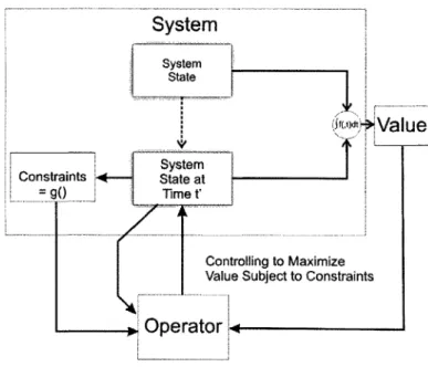
While Figure 4 shows the various components of the system necessary to operate it, the figure tends to suppress the active nature of the operator. A better view of this is shown in Figure 5.
System
System State J+Value
System Constraints State at=gO
Time t' Controlling to MaximizeValue Subject to Constraints
Operator
1
Figure 5 Operator Controlling the System to deliver Value
The figure shows that the system exhibits value and constraints. A new concept introduced by the figure is the state is related to the value of the system. The system state is a time varying property and reflects both the internal state such as configuration of the system as well as the external state such as location. There are certainly systems that exhibit value based on a static state. Examples of these are batteries that are valuable when fully charged; paintings that are valuable when important artists painted them; or homes that are valuable when they can be occupied. These systems do not require operators because the value is inherent in the state of the system. For the systems we will consider, the value is related to the change of state and thus requires an operation (and an operator) to generate value. For airplane systems, for example, value is generated as the state of the aircraft changes from empty to full (internal state) and the location state changes from point A to point B (external state). In any case, the operator manages the state changes subject to constraints for the purpose of generating value.
While Figure 5 is useful for highlighting the role that the operator plays in delivering value using the system, the view it presents is too high level to examine the role of automation in the system. The system must be decomposed further to examine how the automation interacts with the operator.
Hawkins (Hawkins, 1993) identifies the goals of aviation automation as: (1) to improve the performance of the system; (2) to reduce workload on the operators; and (3) to improve the operating economy of the system.
When one considers the performance of the system, we are considering those aspects of the system that impact the immediate value delivery. For example, a feature of an autopilot for a Cessna 172 is a wing-leveling mode. While the autopilot is active, the automation will maintain the wings level, thus improving the performance of the aircraft in maintaining an accurate course. This also
improves the comfort of the passengers. For automation to manage the
performance of the system, it must have some ability to measure the performance variable, and it must have the means of actuating some aspect of the system that affects the variable. In other words, it must be able to measure and affect the state of the system.
Considering the reduction of the operator workload, the intent is to relieve the operator of constantly monitoring some parameter. The automation in this case behaves as a supervisory control with the operator providing set point
information to automation. In this scenario, the automation is an interface
between the operator and the system where the operator specifies a target indication and the automation provides performance indications that indicate how well it meets the target.
When the automation is improving the economic performance of the system, it is actually measuring the state of the system and providing feedback either to the
operator or directly to the system over some trajectory that minimizes some cost to the system. A good example of this is found in car computers that calculate an optimal fuel/air mix ratio to maximize fuel economy. This information is fed back directly to valves that control airflow and fuel into the car engine. In other cases, the information is provided to the operator who has the option to utilize the information or not.
Automation also serves to improve the safety performance of a system(Leveson et al., 1997). In this case, the automation may provide automatic monitoring of constraints. If the system violates these constraints, then the automation may notify the operator or it may provide direct inputs to the system to transform its state from a hazardous to a non-hazardous state.
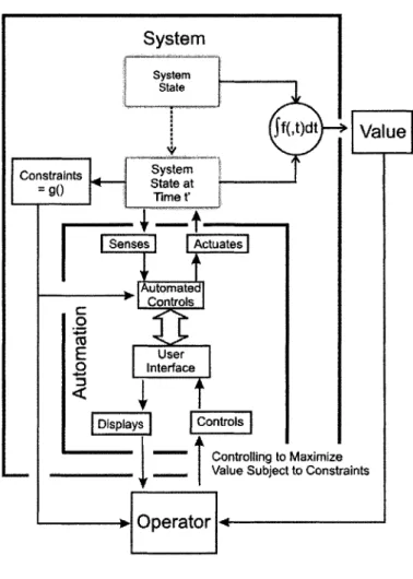
Incorporating these ideas into the model shown in Figure 5 gives the model shown in Figure 6.
System
System State Jf(,t)dtValue
D Slystem l ConstraintsV SsC r Stame t Senses |Actuates| utomate Controls CUE
User 0 Interface Displays Controls """""" Controlling to Maximize Value Subject to ConstraintsOperator :4
Figure 6 System with Automation
The figure still is inaccurate. The figure fails to indicate the stateful nature of
automation. In complex systems utilizing automation, a stateless automation
would be complex to the point of be unusable. For example, a pilot can use an autopilot system to navigate a course from point A to point B or execute a precision approach to an airport. These functions are fundamentally different and are configured and utilized by the pilot in different ways. While it is possible
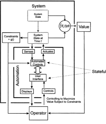
to provide separate interfaces, the functions do not need to be provided at the same time and so providing the interfaces simultaneously is wasteful. Instead, the interfaces are shared and automation states allow the functions to be accessed at separate times. Leveson (Leveson et al, 1997) provides state machine models to represent both the state of the system and the state of the automation. She indicates that the automation, the user interface and the system have their own state machine representation. These ideas are incorporated in Figure 7
System state f(,J)dt Vau onstraints
Opaeato
Time t' AutomatedE
l
Stateful
EU
User 0 Interface Displays Controls """""" Controlling to MaximizeValue Subject to Constraints
P, Operator I
The picture shows that system exhibits constraints, a system state, and a value. The system also contains automation that provides some level of automatic and supervisory control. The automation itself includes an interface with an interface state and a separate automation state.
When one examines the figure, one notices that the automation state changes may not contribute to the value measure. This is not to say that the automation is not valuable. The value is a measure of the primary benefit of the system. The automation simply exists to help to operator achieve the value.
A very important point to understand this model is that the automation is designed and constructed anticipating a certain range of states for the system-the design envelope of system-the system. It is system-the tool of system-the operator but it also constrains the operator in that it filters information to the operator and it filters information from the operator to the system. In this sense, the automation enforces a polig
on the operator. The problem is that when the system deviates from the
anticipated states it is difficult to modify the automation outside of the designer's intent in response. This is the operator's responsibility and is the topic of the
Chapter 3 Endnotes
Hawkins, F. H. (1993). Humanfactors inflight (Second ed.). Brookfield, Vt: Ashgate Publishing Company.
Degani, A., & M. Heymann. (2002). Formal verification of human-automation interaction. Human Factors, 44, 28-43
Leveson, N. G., D. L. Pinnel et al. (1997). Analyzing software specifications for mode confusion potential, Workshopfor Human Error and System
Chapter 4
THE OPERATOR
In Chapter 3, this thesis developed a system model, but only created a place holder for the operator. To bring meaning to the mode confusion model, one must investigate the operator and how he contributes to the overall problem of mode confusion.
As indicated by the previous chapter, the automation is the tool of the operator in order to help him achieve value generation of the system. The operator understands what he wants the system to do, and he responds to situations that are outside of the design envelope of the automation.
Unlike a mechanical system, an operator is a human being and is therefore fuzzy in definition. This section will examine and isolate this fuzziness in order to
develop a model of the operator.
System syse state Beneficiary Value Constraints sta at =
9
Time t' Vauu~bject to Constraints OperatorFigure 8 shows the operator in relation to the system. The figure shows the operator delivering some value to a beneficiary by changing the state of the system. This intention is important because it provides the overall context of the operator's purpose in using the system.
System state
Value Gan, State
By~u
(
Doing Tasks\
N
(
GOAL
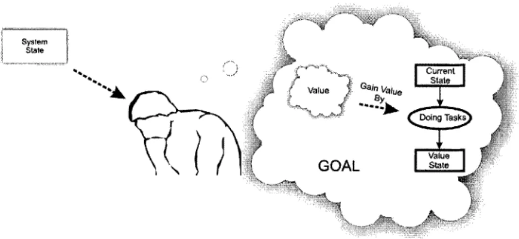
StteFigure 9 The Operator Delivering Value
Figure 9 expands on the act of delivering. In this figure, the value becomes the goal of the operator. She knows that by executing certain tasks, the system will transition from the current state to a "value state". This value state represents the change in the system providing value to the system beneficiary.
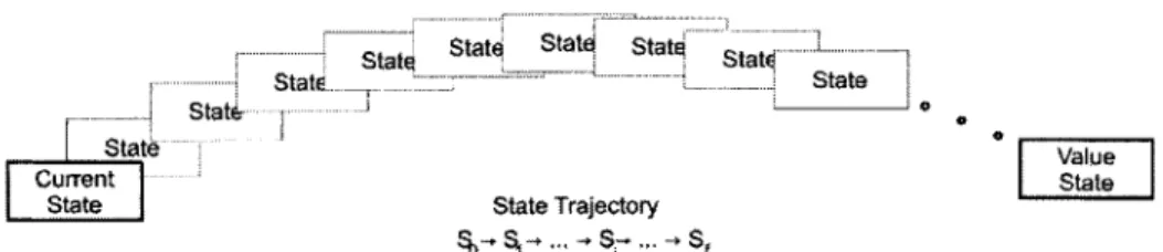
In complex systems, controlling the system from an initial state to a value state is not a monolithic operation. The operator executes a series of tasks that has the effect of changing the system state along some discrete trajectory (Figure 10).
. ... - --- ---
~
Stat State Stat - -...
... _ ... .StatE__ _. .. State
State ... - - a Statee
Stt
ValueCurrent State
State State Trajectory
-% - ... - Sr .. Sf
Figure 10 The Trajectory of System States
Each transition from one state to the next may have its own goals and tasks to accomplish that goal. Thus, as the state of the system changes the immediate
goal changes. Goals are measurable in terms of system state and thus the
operator accomplishes it by driving the system along some state trajectory from the current state to the goal state. For example, say a person intends to drive from Boston, Massachusetts to Portland, Maine. She starts from the parking lot next to her Beacon Hill apartment and next she creates the immediate goal of getting on to Beacon Street. In choosing her goal, she creates a task in her mind
to accomplish it. As she drives through the lot to Beacon Street, she is
constantly comparing her system state to the goal she has and adjusts her tasks and goals accordingly. The representation of monolithic tasks in the mind of the
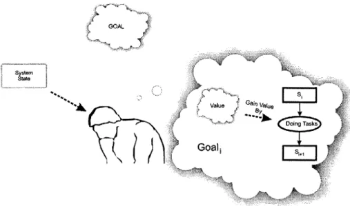
operator could be represented as shown in Figure 11 . Here there is an
immediate goal (Goal) that represents immediate reason for the task at hand. The higher goal (represented as the cloud labeled "GOAL") represents the intention of doing that task.
GOAL
System State
Value Gain ValuIe By
Doing Tasks
Goal
Figure 11 A view of a Monolithic Task in the Context of a Higher Goal
While Figure 9 and Figure 11 show a simplified view of how a person uses a system to deliver a benefit, it neglects the fact that operators are individuals and one individual will behave differently than another. Endsley (Endsley, 2000) indicates that there are individual factors involved in both the perception of the system state and formulating a response. If the woman described in my previous example is a physician and witnesses a person having a heart attack, she might change her goal from driving to Beacon Street to giving medical assistance. If she is not a physician then her goal might be to call for paramedics. The choice of goals and associated tasks depend on one or more individual factors and these need to be accounted for.
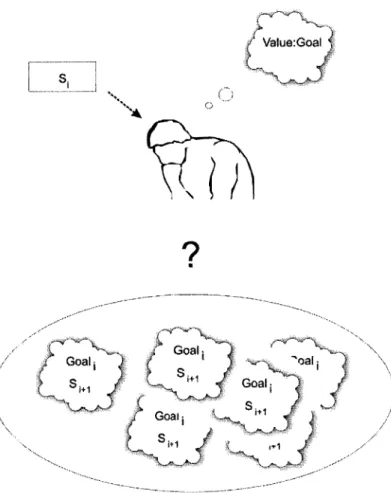
Given a current system state and a terminal value state, individuals must choose what the next state should be. If individuals were machines, one would expect
that choosing the next step would be deterministic. Unfortunately, individuals are a little fuzzier in their behavior and thus an individual may feel that there are many ways to achieve the final goal state and has to choose one of many possible paths as the next step (Figure 12).
Value:Goal
GoalG
GoalG o S 1+1 Goaoal' SS 1+1Figure 12 Choosing What to do Next
Even if there was a clear "next state" and thus the next goal is clear to the
operator, it may be that there are many options available to the individual to get
to the next goal. Each option describes a task and an associated metric that measures the accomplishment of the task. This is illustrated in Figure 13 where the individual faces many possible tasks to achieve a goal.
Tk
str 6 M rc -' k
Tas T.~' Task TrA~'
... i8 L e I Tas ... M Metric T1 k Metric ask r tr Metric meskic
1--j-'.-~J
Task k MercMetric eti ask Tas j~~L
Si S,+Figure 13 Many Ways to get to the Next State
The preference of choosing the next goal and the tasks to accomplish that goal is dependent on the individual. These individual factors make it rather difficult to model an operator because there needs to be some determinism in order to
predict how he operates a system.
To
judge
whether individual factors can be eliminated from the operator model,one must consider what individual factors are. Briefly, these factors and their impact on operator response include:
Psychology: Individual psychology is very important when responding to system events. A person prone to rigorously follow rules may have a problem responding to system events that exceed what has
been described about the system. A very bright
person may not be suitable as an operator of a production line.
Figure 14 Individual Factors
Physical ability: As in basic needs, a person may make a choice in tasks and goals depending on how ably they can execute these tasks. This along with psychology
comprises Endsley's view of individual ability(Endsley, 2000).
Experience: A user who has experienced certain behaviors using the system or analogous systems may adjust his task and goal selection depending on whether or not that behavior is desired.
Expectations: A person who anticipates a certain system event may choose tasks differently then when the event is not expected.
Intentions: The intentions of the operator have a strong impact on task and goal selection. Endsley discusses this in terms of goals and objectives(Endsley, 2000).
The many permutations of these factors could add a great deal of
complexity to the operator model.
Variation
in
A better approach might be to take
>
Behavior
C 0L
advantage of the fact that in some
cases operators have similar
characteristics that cause them to Normin
choose similar goals and tasks given a certain system state and intent.
Some systems lend themselves to Figure 15 Transforming Individuals to operators
this norming of operators and some
do not. For example, most persons who are physically capable can ride a bike. If one looks at each operator of a bicycle system, just about every response factor is quite different from person to person except the physical capability. If one considers another system such as an aircraft system, one discovers that there are federal restrictions as to who can be a pilot and under what circumstances the individual can fly. These restrictions normalize the response factors such that the way individuals respond to various events while operating an aircraft are similar across the collection of people who are considered pilots. Figure 16 shows other means of norming the behavior of operators.
s i A normed operator is an operator
- who can expect to come up with the
same tasks and same goals given a
tS crn!in certain system state. The key is to
identify those goals and tasks given
GOAL S Ysem k
I
7 4SVle Garn Va,
Doing Task
Metric
Goal,
Figure 17 Normed Operator Choosing Task and Goal
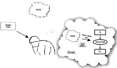
Figure 17 shows the system with the normed operator. With a normed operator, the individual is expected to choose a new goal and tasks to achieve that goal in a
more deterministic way than non-normed operators. The process for the
operator is as follows:
1. The operator observes a system state and evaluates it against his expectations along the state trajectory of the system. His expectations are based on the higher level goal (GOAL), which is his intention.
2. The operator is a normed operator and thus chooses the next goal state in a predictable way.
3. The operator is a normed operator and chooses a task and an associated completion metric in a predictable way. The operator executes this task to transition to the next state.
Referring back to Figure 10 (See page 41), the system is shown following a trajectory from the current state to a value state. To drive the system from one state to the next is generally not a monolithic operation in that there is a single task to accomplish. At the highest level, the operator wants to move the system from the start state to the value state and thus has an associated goal. At the next level, the operator, having driven the system from the initial state to state I, has
the goal of moving the system to state i+1. The overall intention remains
unchanged-to move the system from the start state to the value state, but the immediate goal is to move from the current state to the next state. This is shown in Figure 18.
Similarly, the tasks involved in moving the system to state i+1 may not be themselves monolithic. The operator may have a number of tasks to accomplish that may not meaningfully change the state of the system. For example, assume that the operator is a pilot on an aircraft on an instrument approach to an airport. The overall goal is to transport people from airport 1 to airport 2 and the task that occurs on the system state trajectory is to land the aircraft. Tasks such as tuning the radio, contacting approach control, acquiring the final approach fix, and so forth do not necessarily change the state of the aircraft system such that more value is achieved or more costs are assumed, but they are necessary tasks in accomplishing the state change from "on instrument approach" to "plane on the ground". When we examine one of these subtasks, "tune the radio" the intent remains "land the aircraft". Thus, in the operator's mind there is a hierarchy of goals and associated tasks (Figure 19) with the immediate higher-level goal serving as the intent of the current goal.
GOAL Value - State State GOAL is Intent of Goal Task S - J . 1+1 Metri
Figure 18-Intent of Tasks
GOAL str Value Goal state 0 Se is Intent Of Goal _.. _.Task.- .. metric Z L.1 Goal is Intent of Goal1
~
~
Ts ____ I. 4enFigure 19 Intent of Subtasks
When one accomplishes tasks at the lowest level, one must ensure that the accomplishment of these tasks remain consistent with the accomplishment of the higher level goals. In the previous example, if I tune my radio, I should tune it to the approach control frequency, not some random frequency.
That said the tasks required to tune the radio remain the same regardless of the intent of the operator. For example, there are a number of occasions when a pilot will tune a radio. He will tune a radio when needs to get ATIS information prior to takeoff or landing, he will tune a radio when he needs clearance delivery, he will tune a radio when he needs to deliver a pilot report of weather and so forth. In each case, the task associated with tuning the radio doesn't change, only the metric--e.g. the frequency-changes. If the tasks associated with tuning the radio changed depending on intent, then operators can be confused. From the systems perspective, this means that a component has knowledge of the emergent behavior and thus is coupled with higher level goals. This is an increase the burden of the operator who must manage these tasks.
Chapter 4 Endnotes
Endsley, M. R. (2000). Theoretical underpinnings of situational awareness: A critical review. In Endsley, M. R.et al. (Eds.), Situational awareness analysis and measurement. Mahwah, NJ: Lawrence Erlbaum Associates.
Chapter 5
INTERACTIONS
Chapter 3 created a model of a system that requires some operator to manage the
state transitions. The system was further developed to show an automated
controller and an interface that each had states that changed the information presented to the operator as she was driving the system.
Chapter 4 examined the operator. Operators are human beings and therefore have unique characteristics that make modeling them difficult but by assuming norming the model drives out their individual characteristics so that one can assume that given identical system states and identical goals, operators will behave similarly. The operator model is simply a hierarchical set of goals where the higher level goals provide intent for the lower level goals.
The development of these models was done in relative isolation from one
another. The system model was developed with little consideration of the
operator. The operator in turn was developed with little consideration of the system. The problem of mode confusion is an emergent problem and requires a consideration of the overall system consisting of the value generating system and the goal driven operator. This chapter will discuss the emergent behavior of such a system.
System
[ ]L
Controlling -Via Automation Constraints Stateful Value Operator OMeticFigure 20 Combined Operator and System Model
Figure 20 incorporates the two models together. While this picture expresses the operator as having a single goal with an associated task and completion metric, in reality the operator embodies a hierarchy of goals and tasks.. These goals and tasks change over time as the operator drives the system over a trajectory of states. The picture also shows that the automation is stateful. The automation changes state over time depending on external events or operator needs.
The operator considers that the overall goal of the system is to generate value by transitioning the state of the system from an initial state to a value state. The interface of the automation should enable the operator to monitor important aspects of the system as it follows the state trajectory. The automation controls some aspects of this trajectory sometimes at the discretion of the operator and at other times enforcing some constraints on the operator. As far as the operator is concerned, she needs to be able to measure the system state and compare them to her own goals as to the system performance.
For the system stakeholders, automation may serve one of a number of purposes. These purposes have goals associated with them, but are not always the
immediate goals of the operator. For example, when we consider the
improvement of the performance of the system, the task may be transparent to the operator but some other stakeholder may have a keen interest in the associated goal. These tasks are designed into the automation. Other tasks are
directly assigned by the operator. When one considers the reduction of the
workload of the operator, the automation simply assumes the mechanics of taking one aspect of an operator's goal and controlling the system such that the operator's goal is met. For example, in the altitude hold mode of the autopilot, the automation simply controls the aircraft such that the altitude is maintained. The automation, in general, does not have knowledge of why the altitude is to be maintained, it simply maintains the altitude.
GOAL System State ilL*4 Va inVueu Doing Task
Goal
Set up
the
Automation
Automation
Figure 21 Operator Delegating a Task to Automation
For the operator the automation simply assumes tasks. Starting from the top of Figure 21, one sees the operator exhibiting some goal with a related task and metric. Initially, the operator is responsible for accomplishing the goal, but in order to reduce her workload, she wishes to have the autopilot assume the
responsibility of accomplishing this goal. The process of transferring this
responsibility is called delegating. In the operator's mind, the act of delegating a task means that the meeting of the goal shall be accomplished by the automation. For the automation to assume the task, it is necessary for the operator to communicate the task and its associated metric to the automation (Figure 22).
Since the operator is also ultimately responsible for meeting the task, he must be able to supervise the automation such that he can monitor system performance in the accomplishment of the task (Figure 23).
Goal
Metric
Automation
Figure 22 Delegating a Task to Automation
To delegate successfully a task to the automation, it is necessary to communicate the information necessary to accomplish the task via some interface. A good interface transmits the information in an unambiguous way. When interface is ambiguous, it can be all too easy for an operator to intend to communicate certain task information to the automation when in reality completely different information is provided.
Once the operator delegates a task to the automation, the operator assumes that the automation is controlling the system with respect to the goal until the task is accomplished or cancelled. That said, the operator is still responsible for the successful completion of the task and needs to monitor its performance through some interface. If the performance is incorrect, then the operator will need to adjust the task assignment to the automation or assume the task itself. Similar to the requirements of the interface communicating task information, the interface conveying performance information must be unambiguous and consistent with
the goal of the task. When the interface is ambiguous, the operator may assume that his goals will still be met when in fact they will not be.
The accomplishment of a task means that the automation has controlled the system such that the goal has been achieved. For example, if an operator is a pilot of an aircraft and has the goal to fly from point A to point B, the goal is achieved once the aircraft arrives at point B. If this goal is delegated to the
Performance
Automation
Goal
4....
.. ...--- --- ._________MetricI
Corrections
Figure 23 Operator Monitoring the Automation
automation, then the goal is achieved once the aircraft arrives at point B. When a task is accomplished, the operator needs to be able to confirm this in her own mind. This will allow her to indicate to herself that the goal is achieved and follow-on tasks can be started. Thus the accomplishment of a task must be reflected in the performance feedback to the operator.
Some tasks indicate that the system should maintain a state. An example of such a task includes the wing-leveling feature of autopilots-the purpose here is to maintain wings parallel to the horizon. These kinds of tasks may not have a goal per se in that other tasks depend on it-rather these tasks simplify the
management of the system because one aspect of the system state is maintained by the automation instead of the operator. For the purposes of the model described here, these tasks are no different than tasks that accomplish themselves automatically except that these tasks are always in effect until they are cancelled.
In terms of the automation, task cancelling is when a goal is not achieved but some event causes the automation to enter a state that is no longer goal supporting. These events can originate from the operator, from the system itself without operator input, or even externally from the system. If one considers the bust-the-capture scenario(Palmer, 1995) one can see that the altitude bust-the-capture of an autopilot expresses two goals: the first goal is to climb to a specific altitude; and the second is to hold the altitude subject to constraints of a maximum g-force on the aircraft. Under certain circumstances, if the pilot adjusts her vertical speed, the goal becomes cancelled and the automation assumes a new task of climb at a specific rate. This is an example of an operator cancelling the task and delegating a new task.
One notices that the example given above is in the perspective of the automation. To the operator the issue of whether or not a task was cancelled and a new task delegated depends on the operator's intent. If his intention was not to climb at a specific rate then his goal in now inconsistent with the automation-this is mode confusion. In general, for every task delegated to the automation, there must be a corresponding operator goal. Secondly, for every delegated automation goal that is cancelled, the corresponding operator goal must either be cancelled or assumed by the operator. When these two requirements are met, the operator goals are
said to be consistent with the automation task assignments.
The automation is not static in state. The purpose of states in automation is to separate in time the functions of the automation such that the interfaces can be
simplified. The consequence of this is that some states support certain tasks while other states do not. In terms of the operator, this means that some states are goal supporfing while other states are not. Certain events may occur that change the state of the automation from a goal supporting state to a non-goal supporting state. The remaining discussion in this chapter will focus on this aspect of the problem.
Automation State Goal g3
Not Goal DeSire
Supporting b d
h Goal
Supporting
Figure 24 Goal Supporting Automation States
Figure 24 shows an example of how automation may work given a user goal. Assume an operator has a goal of driving the system to a desired state. The automation is initially in a non-goal supporting state, but transitions to a goal supporting state when the user enters metric information to the automation-indicated by the (a) transition to state (1). In the course of accomplishing the associated task, the automation will transition to state (2), and finally to an end state indicating that the goal is accomplished. The shortest path to achieving the goal is (1) to (2) to (End) occurring when events b and f occur. Outside of this path are exception states-states (1) and (3)-that occur when the automation state is (2) and events (c) or (d) occur. An exception state is a state that occurs outside of the shortest path. Lastly, there exists two transitions-(g) and (h)-that cause automation to go from a goal supporting state to a non-goal supporting state.
The transition (h) only occurs when the goal has been accomplished while (g) occurs when the goal is NOT accomplished.
The operator is responsible for monitoring the performance of the automation. While each of the automation states (1)-(3) ultimately support the overall goal, each state has an implication as to whether or not the goal is close to
accomplishment. The automation must be in state (2) for the automation to
accomplish the goal, but it starts in state (1). If the automation is in state (3) then the automation may leave the goal supporting states altogether if (g) occurs otherwise it will stay in (3) or if (e) occurs, the state will transition back to (1).
If an operator is aware of these states, he must be able to anticipate the transitions or be at least aware that the transitions have taken place. Anticipation requires that the operator is able to understand the purposes of each state and is able to monitor those conditions that cause a transition from one state to the next. In the operator's mind, these can also be goals with associated tasks and metrics measuring task accomplishment (Figure 25). The difference is that the
automation performs these tasks with or without operator intervention. The
Excepton g b d Subgoall Subgoa12 Goal
Figure 25 Automation States with Operator Goals
Figure 25 shows the goals of each state. This does not help us understand what will cause the operator to follow the automation. The automation may change states and it is important that the operator follow along. If one suppresses the automation states and simply examines how the operator follows the state, one gets the drawing shown in Figure 26.
NOT Goal (g*xMgx*g) Exception (e*xM *e) Subgoall (b*xM *b) (d*xM x*d) (c*xM C Subgoal2 (f*xMx*f) Goal
Figure 26 Operator Goals
This is analogous to the automation state diagram with an important difference.
Instead of the events, one sees a special notation. For example when the
automation transitions from state (1) to (2) due to event (b), the operator is expected to transition from Subgoall to Subgoal2 due to some events (b*x Mb
x*b). b*-inputsfrom the operator-refer to the set of all operator inputs that is required to cause the automation to change states from (1) to (2). *b-ouputs to the operator -refer to the set of outputs to the operator that cause her to recognize that (1) is transitioning to (2). Mb is a matrix whose elements are either