HAL Id: hal-00707078
https://hal.archives-ouvertes.fr/hal-00707078
Submitted on 14 Jun 2012
HAL is a multi-disciplinary open access
archive for the deposit and dissemination of sci-entific research documents, whether they are pub-lished or not. The documents may come from teaching and research institutions in France or abroad, or from public or private research centers.
L’archive ouverte pluridisciplinaire HAL, est destinée au dépôt et à la diffusion de documents scientifiques de niveau recherche, publiés ou non, émanant des établissements d’enseignement et de recherche français ou étrangers, des laboratoires publics ou privés.
An assembly process model for method engineering
Jolita Ralyte, Colette Rolland
To cite this version:
Jolita Ralyte, Colette Rolland. An assembly process model for method engineering. International Conference on Advanced information Systems Engineering, 2001, Switzerland. pp.1. �hal-00707078�
An assembly process model for method engineering
Jolita Ralyté, Colette Rolland Centre de Recherche en Informatique
Université Paris 1 Sorbonne 90, rue de Tolbiac, 75013 Paris, France
e-mail : ralyte, [email protected]
Abstract
The need for a better productivity of system engineering teams, as well as a better quality of products motivates the development of solutions to adapt methods to the project situation at hand. This is known as situational method engineering. In this paper we propose a generic process model to support the construction of a new method by assembling method chunks generated from different methods that are stored in a method base. The emphasis is on the guidance provided by the process model, as well as on the means underlying guidelines such as similarity measures and assembly operators. The process model is exemplified with a case study.
1
Introduction
We are concerned with Situational Method Engineering (SME). SME aims at defining information systems development methods by reusing and assembling different existing method fragments. The term method fragment was coined by Harmsen in [Harmsen 94] by analogy with the notion of a software component. Similarly to the component driven construction of software systems, SME promotes the construction of a method by assembling reusable method fragments stored in some method base [Seaki 93], [Harmsen 97], [Rolland 98a], [Ralyte 99b]. As a consequence SME, favours the construction of modular methods that can be modified and augmented to meet the requirements of a given situation [Harmsen 94], [Slooten 93]. Therefore, a method is viewed as a collection of method fragments that we prefer to call method chunks [Rolland 96], [Ralyte 99b] to emphasise the coherency and autonomy of such method modules. New methods can be constructed by selecting fragments/chunks from different methods which are the most appropriate to a given situation [Brinkkemper 98], [Plihon 98]. Thus, method fragments/chunks are the basic building blocks which allow to construct methods in a modular way.
The objective of our work is to propose a complete approach for method engineering based on a method chunk assembly technique. In previous papers [Rolland 98a], [Ralyte 99b] we presented a modular method meta-model allowing to represent any method as an assembly of the reusable method chunks. In this paper we are dealing with the method chunk assembly process. We present a generic process model, the Assembly Process Model (APM), to guide the assembly of method chunks using different strategies depending on the type of situation in which the assembly activity has to be carried out. Chunk assembly is the support of situational method engineering and therefore we propose a Method Engineering Process Model (MEPM) providing several different ways to assemble chunks with the objective of constructing new methods or enhancing the existing methods by new models and/or new ways of working. Whereas the APM views the assembly of method chunks ‘in the small’, the MCPM takes a broader view where assembling method chunks is part of a larger method engineering process. As a consequence, the APM is embedded in the MEPM.
Both process models, namely the APM and the MEPM, are expressed using the same notations provided by a process meta-model. A process meta-model is an abstraction of different process models, i.e. a process model is an instance of a process meta-model. In this paper, we use the strategic process meta-model presented in [Rolland 99] and [Benjamen 99]. Following this meta-model, a process model is presented as a map and a set of associated
guidelines. Such representation of the process model allows us to provide a strategic view of
different processes. Indeed, this view tells what can be achieved - the intention, and which
strategy can be employed to achieve it. We separate the strategic aspect from the tactical
aspect by representing the former in the method map and embodying the latter in the guidelines. By associating the guidelines with the map, a smooth integration of the strategic and the tactical aspects is achieved.
This paper is organised as follows: section 2 highlights the need for different strategies for assembling method chunks to form a new method and motivates different ways of method engineering based on method chunk assembly. The former is encapsulated in the APM whereas the latter is captured in the MEPM. In section 3, we take the view of method engineering ‘in the large’ and present the method engineering process (MEPM). The MEPM includes the assembly process model which is presented in section 4. In section 4, we present the assembly process model (APM) and discuss the various techniques that support it in order to carry out the assembly activities in a guided way. Section 5 illustrates the approach with an example demonstrating the process step by step. Section 6 draws some conclusions and discussions around our future work. Finally, a brief remainder of the notion of a method chunk is given in the Appendix.
2
Chunk assembly and method engineering
2.1 Chunk assembly
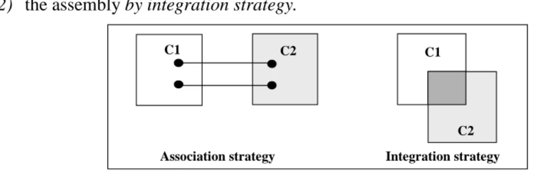
The attempts to define assembly processes [Brinkkemper 98], [Punter 96], [Song 95] highlight the assembly of method fragments as rather independent and supplementary to one another. A typical example would be to adding a given way of working some new activity borrowed from another method and/or adding to the product model of one method a new concept borrowed from another method. In such a case, the assembly mainly consists in establishing links between the ‘old’ elements and the ‘new’, added ones. We found cases quite different where elements to assemble are overlapping. This led us to the identification of two assembly strategies :
1) the assembly by association strategy and
2) the assembly by integration strategy.
C1 C2 C1
C2 Integration strategy Association strategy
Figure 1 : Strategies to assemble method chunks
As shown in Figure 1, the first strategy is relevant when the method chunks to assemble do not have elements in common. This might occur when the end product of one chunk is used as a source product by the second chunk. For example, the chunk producing use cases and the
chunk constructing the system object structure can be assembled to get a method with a larger coverage than any of the two initial ones. The assembly process is therefore mainly dealing in making the bridge.
The second strategy is relevant to assemble chunks that have similar engineering objectives but provide different ways to satisfying it. In such a case, the process and product models are overlapping (Figure 1) and the assembly process consists in merging overlapping elements. The integration strategy will be necessary, for example, to assemble two different chunks dealing both with a use case model construction.
These two strategies are embedded in the assembly process model (APM) presented in section 4.
2.2 Method construction
The assembly of method chunks is a means, a technique to construct a method in a reuse driven fashion. However, method construction is not restricted to chunk assembly. It includes, for example, the elicitation of requirements for the method to construct, amend or enhance. Besides, the ways the assembly technique will be used differ depending of the objective assigned to the situational method engineering project. There are many different reasons for constructing a new method. We identified three of them :
1) to define a brand new method to satisfy a set of situational requirements, 2) to add alternative ways-of-working in a method to its original one, 3) to extend a method by a new functionality.
Each of these delineates a specific strategy for method engineering that we have embedded in the method engineering process model (MEPM).
The first strategy is relevant in situations where either there is no method in use or the one in use is irrelevant for the project (or class of projects) at hand. The second strategy is relevant when the method in use is strong from the product point of view but weak from the process viewpoint. Enhancing the process model of the existing method by one or several new ways of working is thus the key motivation for method engineering. The third strategy is required in situations where the project at hand implies to add a new functionality to the existing method which is relevant in its other aspects.
We present the method engineering process in the next section, whereas the assembly process model is presented in section 4.
3
The method engineering process model (MEPM)
Figure 2 shows our proposal to engineer a method through an assembly of method chunks. We use the strategic process meta-model [Rolland 99], [Benjamen 99] to represent our process model as a map with associated guidelines. A map is a directed labelled graph with
intentions as nodes and strategies as edges. The core notion of a map is the section defined as
a triplet <source intention, target intention, strategy>. A map includes two specific strategies,
Start and Stop to start and stop the process, respectively. As illustrated in Figure 2, there are
several paths from Start to Stop. A map therefore includes several process models that are selected dynamically when the process proceeds, depending on the current situation. Each section is associated to a guideline that provides advice to fulfil the target intention following the section strategy. Furthermore, a section can be refined as an entire map at a lower level of granularity.
The method engineering map in Figure 2 includes two intentions in addition to Start and Stop,
Specify method requirements and Construct method. The latter corresponds to the method
engineering’s essential goal, whereas the former is the prerequisite for the latter. The formulation of this intention, Specify method requirements means that our approach is requirements-driven. In order to construct a new method, we propose to start by eliciting the requirements for the method engineering activity.
The map identifies two different strategies to Specify method requirements, namely the
intention driven strategy and the process driven strategy. Both lead to a set of requirements
expressed as a map that we call the requirements map (developed in the example of section 5). However, each strategy corresponds to a different way of eliciting the requirements. The former is based on the inventory of engineering goals whereas the latter infers these goals from an analysis of the engineering activities that must be supported by the method.
Once the requirements have been elicited, the intention Construct method can be achieved. The method engineering map of Figure 2 shows three different strategies to help the method engineer to achieve this intention. They are the following : from scratch assembly strategy,
enhancement driven strategy and extension driven assembly strategy. The three strategies
correspond to the three method engineering situations that were identified and motivated in the previous section. The from scratch assembly strategy corresponds to situations where a brand new method has to be developed, whereas the two others, enhancement driven strategy and extension driven assembly strategy, are relevant when a method already exists, and needs either enhancements or extensions. As indicated by the names of the strategies, the three proposed ways are based on a method chunk assembly technique developed in the next section. Stop Specify method requirements Construct method Start process driven strategy intention driven strategy extension driven assembly strategy completeness driven assembly strategy from scratch assembly strategy requirements correction strategy validation strategy
Figure 2 : The method engineering map
Backtracking to the requirements definition is possible thanks to the requirements correction
strategy.
Finally, the validation strategy helps verifying that the assembly of the selected method chunks satisfies all requirements and ends the method engineering process.
According to the map meta-model used above to model the method engineering process, each section of the map is (a) associated to a guideline providing advice on how to proceed to achieve the target intention and (b) can be refined as a map of a finer level of abstraction. For
the sake of space we do not present the guidelines associated to every section of the method engineering map (see [Ralyte 01] for details) but concentrate on the refinement of the section <Specify method requirements, Construct method, from scratch assembly strategy> dealing with the assembly of method chunks. The refined map of this section models the method chunk assembly process. The APM (assembly process model) is presented in detail in the next section.
4
The process model for method chunk assembly (APM)
4.1 Overview of the assembly map
This section presents the assembly map guiding the selection of method chunks matching a set of situational requirements and their assembly to form a new method. It is a generic process model in the sense that it includes a number of strategies to retrieve and assemble chunks providing solutions for the different engineering situations the method engineer may be faced with. In particular the map includes two strategies (integration strategy and association
strategy) to assemble chunks that we identified from the literature and case studies and
introduced in section 2.
The process model is presented as a map, the assembly map, in Figure 3.
Stop Assemble chunks requirements driven strategy integration strategy completeness strategy aggregation strategy decomposition strategy Select a chunk association strategy Start completeness strategy refinement strategy evaluation strategy
Figure 3 : The assembly map
As shown in Figure 3, the assembly process model proposes several different ways to select chunks matching requirements as well as different strategies to assemble them. It is based on the achievement of two key intentions : Select a chunk and Assemble chunks. The achievement of the first intention leads to the selection of chunks from the method base that match the requirements. The second intention is satisfied when the selected chunks have been assembled in a coherent manner.
The process starts by the section <Start, Select a chunk, requirements driven strategy> . The guideline associated to this section helps the method engineer to select candidate chunks that are expected to match the requirements expressed in the requirements map (the requirements map results of the achievement of the intention Specify method requirements in Figure 2). It suggests to formulate queries to the method base giving values to the attributes of the descriptors and interfaces of chunks (the notions of chunk interface and chunk descriptor are recalled in the Appendix) to identify the chunks that are likely to match part or the totality of the requirements map.
Any time a chunk has been retrieved, the assembly map suggests to validate this candidate chunk by applying the evaluation strategy. The evaluation strategy helps in evaluating the
degree of matching of the candidate chunk to the requirements. This is based on similarity measures between the requirements map and the map of the selected chunk. We present these similarity measures in section 4.2.
The decomposition, aggregation and refinement strategies help to refine the candidate chunk selection by analysing more in depth if the chunk matches the requirements.
The decomposition strategy is relevant when the selected method chunk is an aggregate one having some component parts that may not be required. The decomposition strategy helps to select those which are the adequate ones.
The aggregation strategy is relevant when the candidate chunk partly covers the requirements. This strategy suggests to search for an aggregate chunk containing the candidate chunk based on the assumption that the aggregate method chunk might provide a solution for the missing requirements.
The refinement strategy proposes to search for another chunk satisfying the same intention but providing a set of guidelines richer than those of the candidate chunk.
If the candidate chunk has been selected and covers the whole requirements map, the assembly map suggests to progress to the Stop intention following the completeness strategy. When at least two chunks have been selected, the method engineer can progress to the assembly of these chunks. Two strategies, namely the integration strategy and the association
strategy, are proposed by the assembly process model of Figure 3 to fulfil the intention Assemble chunks. As discussed in section 2, the choice of the strategy depends of the presence
/absence of overlap between the chunks to assemble.
If the two chunks help to achieve the same intention in the system engineering process and to construct the same or a similar product, the strategy by integration must be chosen. If the selected method chunks do not overlap in terms of intention to achieve and product to construct, then the strategy by association must be selected. In the first case where chunks partially overlap, the integration of these chunks produces a new method whose product and process models are ‘richer’ than those of the initial chunks. With the second strategy for assembling chunks dealing with different aspects of system design, and supplementing one another, the result is a new method providing a larger coverage of design activities. We present the two strategies in more detail in 4.3 and 4.4.
In order to check if the current chunk assembly matches the requirements, the method engineer shall use the completeness strategy. If the response is a positive one, the assembly process ends. In the reverse case, other chunks have to be selected and assembled to gain the required method completeness. This will be achieved by enacting the Start section again. The two assembly strategies use assembly operators, similarity measures and quality
validation rules. The former and the latter were presented in [Ralyte 99a]. Their use will be
exemplified in section 5. Just as a reminder, let us mention that there are two types of operators to assemble process models parts and product models parts, respectively. The similarity measures are used to compare chunks before their assembly and to identify whether they are overlapping. This will help to choose the right strategy between the integration
strategy and the association strategy. We present the similarity measures in the next section.
4.2 Similarity measures
Measures to estimate the similarity of conceptual schemas have been proposed by several authors, for different purposes : in order to identify reusable components [Castano 92], [Castano 93] and to select these components [Jilani 97]. Generally, these approaches measure
the closeness between entities of different conceptual schemas by evaluating the common properties and links with other entities [Castano 93]. The global complexity of the schemas is also taken into account. Bianco et al. [Bianco 99] proposes similarity metrics to analyse heterogeneous data base schemas. These metrics are based on the semantic and structural similarity of elements of these schemas. Other approaches are proposed to help indexing [Diamantini 99], grouping and selection of similar data [Papadopoulos 99]. [Poels 00a] defines distance measures for software entities. The metrics to measure the similarity of textual data have been used in the search of textual documents [Besançon 99]. In the information systems reengineering domain, distance measures have been proposed to evaluate changes in enterprise models [Poels 00b].
In our approach we use measures inspired from those proposed by [Castano 93] and [Bianco 99]. We distinguish two types of measures : those which allow to measure the similarity of the elements of product models and those which allow to measure the closeness of process
models elements. We present them in turn.
4.2.1 Product models similarity measures
We use semantic and structural measures to compare elements of product models.
The Name Affinity (NA) metric allows us to measure the semantic similarity of concepts belonging to different product models. To apply this measure, the concepts of the chunks
must be defined in a thesaurus of terms. Moreover, the synonymy (SYN)and the hyperonymy
(HYPER ) relationships between these concepts must be defined. The SYN relation connects
the terms ti and tj (ti ≠ tj) which are considered as synonyms. This is a symmetrical relation.
For example, <Goal SYN Objective>. The HYPER relation connects two terms ti and tj (ti ≠ tj) where ti is more general than tj. This is not a symmetrical relation. The inverse relation is
the hyponymy (HYPO). For example, <Scenario HYPER Exceptional scenario>.
The thesaurus of terms is a network where the nodes are the terms and the edges between the nodes are the terminological relations. Every terminological relation R ∈{SYN , HYPER
/HYPO} has a weight
σ
R. For example,σ
SYN =1 andσ
HYPER/HYPO =0.8. Therefore, the name affinity metric is defined as follows: → ∗ ∗ > < = − else 0 ) n(e ) n(e if ... ) n(e ) n(e if 1 )) n(e ), n(e ( kl m ij ) 1 ( 1 kl ij kl ij R m R SYN NA σ σ
where n(eij)→ mn(ekl) is a length of the path between eij and ekl in the thesaurus and m ≥ 1,
σnR shows the weight of the nth relation in n(e ) n(ekl) m
ij → .
The semantic similarity is not sufficient to determine if two concepts are similar. We also need to compare their structures. The measure of the structural similarity of concepts is based on the calculation of their common properties and their common links with other concepts. Thus, to obtain the Global Structural Similarity of Concepts (GSSC) we need to measure the structural similarity of their properties and the structural similarity of their links with other concepts. These measures are respectively called Structural Similarity of Concepts (SSC) and
Adjacent Similarity of Concepts (ASC).
The Structural Similarity of Concepts (SSC) is used to compare two concepts with respect to their structural properties. It calculates the proportion of common properties of the two
concepts. The similarity of the structural properties is measured by the Structural Affinity of
Properties (SAP). The properties of two concepts are called ‘common’ if their SAP has a
value strong or weak correspondence.
The Adjacent Similarity of Concepts (ASC) allows us to measure the structural similarity of two concepts with respect to their relationships with other concepts in the corresponding product models. The AAC calculates the proportion of the adjacent concepts which are common to both concepts.
The formulas are as follows :
≠ = ≤ = = = ∗ = ∗ = + =
∑
∑
= = ) d(p ) d(p or 0 ) p , NA(p if different ) d(p with compatible ) d(p and 1 ) p , NA(p if ence correspond weak ) d(p ) d(p and 1 ) p , p ( NA if ence correspond strong ) p , p ( SAP c ato concepts adjacent of Number ) c and c to concepts adjacent commun of Number ( 2 ) c , ASC(c c in properties of Number ) c and c in properties common of Number ( 2 ) c , SSC(c 2 ) c , ASC(c ) c , SSC(c ) c , GSSC(c kl ij kl ij kl ij kl ij kl ij kl ij kl ij 2 1 i i 2 1 2 1 i 2 1 2 1 2 1 2 1 2 1 2 1 i4.2.2 Process models similarity measures
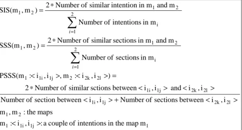
In this section we propose metrics to compare elements of process models i.e. of maps (chunk process models are maps - see the Appendix for more). Elements to compare are intentions, sections and maps themselves to evaluate the global similarity of maps.
Let us start with the measure of the semantic similarity of map elements. We use two kinds of semantic similarity : the Semantic Affinity of Intentions (SAI) and the Semantic Affinity of
Sections (SAS).
The Semantic Affinity of Intentions (SAI) is used to measure the closeness of two intentions. This metric is based on the comparison of the two parameters composing the intention : verb and target. The SYN relation is used to compare the corresponding parameters of two intentions. The two intentions are considered as similar if their verbs and their targets are synonyms.
The metric called Semantic Affinity of Sections (SAS) measures the closeness of two sections. A section is defined as a triplet <source intention, target intention, strategy>; therefore, the measure of the semantic affinity of two sections is based on the measure of the SAI of its source intentions, the SAI of its target intentions and the application of the SYN relation between their strategies.
The two semantic similarity measures are defined as follows :
S = ∧ = ∧ = > < > < ∧ = else 0 s SYN s 1 ) i , AI(i 1 ) i , SAI(i if 1 ) s , i , i , s , i , i SAS( else 0 .target)) i SYN .target (i .verb) i SYN .verb (i if 1 ) i , SAI(i kl ij l j k i kl l k ij j i j i j i j i
The structural similarity measures are needed to compare the structures of two maps and to identify their overlapping parts. We use two kinds of structural measures : the Structural
Similarity by Intentions (SSI) and the Structural Similarity by Sections (SSS).
The Structural Similarity by Intentions (SSI) is used to measure the proportion of similar intentions in two maps. This is based on the calculation of the SAI of their intentions.
The Structural Similarity by Sections (SSS) allows us to measure the proportion of similar sections in two maps.
Sometimes, we also need to compare the proportion of similar sections for a couple of intentions which exist in the two maps. For this we introduce the Partial Structural Similarity
(PSS) metric.
The three measures are defined as follows :
1 1j 1i 1 2 1 2l 2k 1j 1i 2l 2k 1j 1i 2l 2k 2 1j 1i 1 2 1 i 2 1 2 1 2 1 i 2 1 2 1 m map in the intentions of couple a : i , i : m maps the : m , m i , i between sections of Number i , i between section of Number i , i and i , i between sctions similar of Number 2 ) i , i : m , i , i : PSSS(m m in sections of Number m and m in sections similar of Number 2 ) m , SSS(m m in intentions of Number m and m in intention similar of Number 2 ) m , SIS(m > < > < + > < > < > < ∗ = > < > < ∗ = ∗ =
∑
∑
= = i iThese metrics will be exemplified in the case study presented in section 5.
We now present the two ways to assemble method chunks, i.e. the integration and association
strategies, in more detail. This is done in the next section by refining the two sections <Select a chunk, Assemble chunks, integration strategy> and < Select a chunk, Assemble chunks, association strategy> of the assembly map shown in Figure 3, respectively.
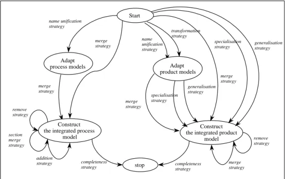
4.3 Chunk assembly by integration
Figure 4 shows the process model corresponding to the assembly by integration strategy, the
integration map. The map of Figure 4 is a refinement of section <Select a chunk, Assemble chunks, integration strategy> of Figure 3.
The assembly process by integration, or the integration process for short, consists in identifying the common elements in the chunks product and process models and merging them. The maps of the these chunks must have some similar intentions and their product models must conceptualise the same objects of the real world by using similar concepts.
merge strategy stop merge strategy generalisation strategy specialisation strategy addition strategy completeness strategy completeness strategy remove strategy remove strategy Adapt process models merge strategy section merge strategy transformation strategy Construct the integrated process
model
Construct the integrated product
model name unification strategy merge strategy name unification strategy generalisation strategy merge strategy specialisation strategy Adapt product models Start
Figure 4 : Integration process map
As shown in Figure 4, the method engineer can start the assembly process by the integration of the process models followed by the integration of the product models or vice versa. At every moment he can navigate from the process models integration to the product models integration and vice versa.
Let us first consider the assembly of chunks process models, i.e. maps. It might be necessary to make some terminology adjustments of maps before their integration The mechanism of integration merges similar intentions that must have the same name. This is not necessarily the case in the initial chunks selected for assembly : intentions having the same semantics may have different names whereas semantically different intentions my be named exactly the same. The guideline associated to the section <Start, Adapt process models, name unification
strategy> helps to identify a couple of similar intentions requiring some name unification.
The SAI (section 4.2.2) measure is used to detect that the intentions are similar and then, the
RENAME_INTENTION operator (see the note about operator in 4.1) is recommended to unify
their naming.
Either directly or after having proceeded to the unification of names, the method engineer can move to the intention Construct the integrated process model. The two sections <Start,
Construct the integrated process model, merge strategy> and <Adapt process models, Construct the integrated process model, merge strategy> use the same guideline, i.e. suggest
the same way to proceed. The guideline recommends the use of the MERGE_INTENTION
operator for each couple of similar intentions.
The integration of product models is based on the identification of couples of similar concepts to be merged. Again, this might require naming revision or can be done directly. The former can be achieved by two different strategies, the name unification strategy and the
transformation strategy whereas the latter is achieved by the merge strategy, the specialisation strategy and the generalisation strategy. We consider them in turn.
Two concepts to be merged must have the same semantics. In addition, if their structures are identical, they must have the same name. Vice-versa, if their structures are different, they must be named differently. For this reason, the product models integration may also be preceded by an adaptation step. The map (Figure 4) proposes two strategies to progress to the
intention Adapt the product models : the name unification strategy and the transformation
strategy.
The name unification strategy must be selected to solve the problem of naming ambiguity of concepts belonging to the two different product models. The guideline associated to the section <Start, Adapt product models, name unification strategy> uses the NA and GSSC measures (section 4.2.1) to identify a couple of such concepts and proposes to rename one of
them by applying the RENAME_CONCEPT operator.
The transformation strategy must be selected when the same real world object is modelled differently in the two product models. For example, the object may be presented by a concept in one model and by a link between two concepts or by a structural property of another concept in the other model. The guideline associated to the section <Start, Adapt product
models, transformation strategy> helps to identify the couples of elements that need to be
unified (concept and link, concept and property, or link and property) and to apply one of the
product assembly operators OBJECTIFY_LINK or OBJECTIFY_PROPERTY according to
the situation.
The same product integration strategies are possible to fulfil the intention Construct the
integrated product model independently of the starting intention, the Start intention or the Adapt product models intention. There are three strategies: the merge strategy, the generalisation strategy and the specialisation strategy (Figure 4). The guidelines associated to
the respective sections are identical. For example, the guideline associated to the section
<Start, Construct the integrated product model, merge strategy> is the same as the one
associated to the section <Adapt the product models, Construct the integrated product model,
merge strategy>.
The merge strategy is applicable to merge concepts with similar semantics and similar structure. The corresponding guideline helps to identify a couple of similar concepts by applying the NA and GSA measures and to apply the product assembly operator
MERGE_CONCEPT.
The generalisation strategy shall be used when the two concepts have the same semantics but different structures : the GSA measure helps evaluating if the difference of their structures forbid their merging. The guideline associated to the sections <Start, Construct the integrated
product model, generalisation strategy> and <Adapt the product models, Construct the integrated product model, generalisation strategy> proposes to generalise the two concepts
into a new one. The common properties of the two concepts are attached to the new concept whereas the specific properties are kept attached to the specialised concepts. The
GENERALISE operator is used to support this transformation. The two initial concepts must
have different names before their generalisation; therefore the name unification strategy shall be required first.
Finally, the specialisation strategy is required when one concept represents a specialisation of the other concept. The associated guideline to sections <Start, Construct the integrated
product model, specialisation strategy> and <Adapt product models, Construct the integrated product model, specialisation strategy> introduces a specialisation link between the two
concepts by applying the SPECIALISE operator. As in the previous case, the two initial concepts must have different names before their specialisation.
At any step of the integration process, it could be necessary to improve the current solution. The map of Figure 4 proposes three strategies to refine the integrated process model; these are : the remove strategy, the addition strategy and the merge section strategy.
The remove strategy deals with the need to remove elements in the integrated model. Many different reasons can justify such removals; for example to remove a useless or redundant guideline. The guideline associated to the section <Construct the integrated process model,
Construct the integrated process model, remove strategy> suggests the use of the
REMOVE_SECTION operator to perform this operation.
Some new guidelines can also be required to complete the integrated process model, particularly if the integrated product model integrates generalisation and/or specialisation of concepts. The integrated process model needs to be extended in these cases. The guideline associated to the section <Construct the integrated process model, Construct the integrated
process model, addition strategy> helps doing so by applying the ADD_SECTION operator. Finally, the merge section strategy suggests to merge sections which are duplicates. The guideline associated to the section <Construct the integrated process model, Construct the
integrated process model, merge strategy> applies the operator MERGE_SECTION to achieve this goal.
Similarly, it can be necessary to improve the current version of the integrated product model. The integration map of Figure 4 proposes two strategies for guiding the integrated product model, namely the remove strategy and the merge strategy.
The remove strategy allows to eliminate concepts, links or properties of the integrated product model, as the merging activity might have led to duplicated ones. The guideline associated to the section <Construct the integrated product model, Construct the integrated product model,
remove strategy> applies one of the operators REMOVE_CONCEPT or REMOVE_LINK or
REMOVE_PROPERTY according to the situation at hand.
To end the integration process the method engineer is invited to apply the quality rules and to verify the coherence and the completeness of the obtained product and process models following the completeness strategy.
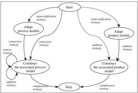
4.4 Chunk assembly by association
In this section we consider the assembly of method chunks carried out following the
association strategy. Figure 5 shows the process model corresponding to this assembly
strategy. The map of Figure 5 is a refinement of the section <Select a chunk, Assemble
chunks, association strategy> of the main assembly map presented in Figure 3.
connection strategy Stop addition strategy addition strategy completeness strategy completeness strategy remove strategy Adapt process models Construct the associated process
model
Construct the associated product
model name unification strategy connection strategy name unification strategy addition strategy Start Adapt product models
The assembly process by association, the association process for short, consists in connecting chunks such that the first one produces a product which is the source of the second chunk. Thus, the association process may consist in simply ordering chunks processes and relating chunks products to one another.
The association process is simpler than the integration process. The association of product models is achieved by establishing links between concepts or adding elements connected to other concepts. The association of the process models consists in ordering the process activities provided by the two different models and possibly adding some new activity. As in the case of the integration driven assembly, the association of chunks may also require the unification of their terminology. The name unification strategy is provided to unify names in maps and product models. Maps of chunks in this case should not have similar intentions. Thus, if there are intentions with the same name, these are homonyms and one of these intentions must be renamed. The SAI (section 4.2.2) measure must be applied to the suspected intentions. Similarly, the chunks product models should not contain similar concepts. Therefore, two concepts having the same name should be homonyms requiring the renaming of one of them. The NA and GSSC (section 4.2.1) measures can be used to evaluate the
similarity of concepts. The operators RENAME_INTENTION and RENAME_CONCEPT are
suggested to be applied by the corresponding guideline.
If the two maps do not have any naming problems, the construction of the associated process model can start directly whereas the Adapt process models intention has to be fulfilled first in the reverse case. Then, the connection strategy is needed to carry out the association.
The guidelines associated to the sections <Start, Construct the associated process model,
connection strategy> and <Adapt process models, Construct the associated process model, connection strategy> are identical. They suggest a plan of action in three steps : (first), to
determine the order in which the chunk processes must be executed; (second), to identify in the map of the first ordered chunk the intention that results in the product which is the source to the second chunk process, and (third) to merge this intention with the Start intention of the
second chunk by applying the MERGE_INTENTION operator.
A similar set of strategies is proposed in Figure 5 to deal with the association of product models. The product models may also by associated directly or after some terminological adaptation. Thus, the guidelines associated to sections <Start, Construct the associated
product model, addition strategy> and <Adapt product models, Construct the associated product model, addition strategy> are identical. They advise to identify the concepts in the
product models which can be connected by a link or by introducing an intermediary concept. These guidelines recommend the use of the product assembly operators ADD_LINK or
ADD_CONCEPT depending of the situation at hand.
Refinement of the associated process model may be required and the remove and addition strategies are proposed to deal with this in the map (Figure 5). They are the same as the corresponding strategies in the integration map (Figure 4).
Finally, the validation of the resulting product and process models must be performed to end the association process. The method engineer is invited to apply the quality rules and to verify the coherence and the completeness of the resulting method chunk using the completeness
5
Application example
In this section we illustrate the use of the method engineering process model with an example. We show how the method engineering map and its refined maps guide a method engineer step by step to construct a new method by retrieving and assembling method chunks.
Let us suppose that a method engineer has to construct a method supporting the elicitation of functional system requirements in a goal-driven manner, to conceptualise them using textual devices such as scenarios or use cases, to validate them in an animated fashion and finally to document them.
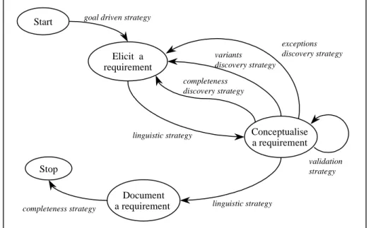
According to the method engineering map presented in Figure 2, the first intention to achieve is to Specify method requirements. The process driven strategy looks adapted to the situation at hand as the requirements are expressed above in a process-oriented way. Assume that the application of this strategy leads to the following requirements map (Figure 6):
Stop
Elicit a requirement goal driven strategy
Document a requirement completeness strategy variants discovery strategy validation strategy linguistic strategy completeness discovery strategy Conceptualise a requirement linguistic strategy Start exceptions discovery strategy
Figure 6 : The requirements map of the application example
Once the requirements for the new method have been elicited, the method engineering map suggests to Assemble Chunks. As the objective is to construct an entirely new method, the
from scratch assembly strategy proposed in the method engineering map (Figure 2) is chosen.
The refined map of this assembly process (Figure 3) proposes to start with the selection of method chunks matching part or the totality of the requirements map. The guideline suggests to formulate queries to the method base in order to retrieve candidate method chunks. These queries give values to the different attributes of chunk interfaces and chunk descriptors. The search in the application case is based on the following values : application domain =
information systems, design activity = requirements engineering, reuse intention = discover functional system requirements, situation = problem description. Let’s assume that chunks
with the following interfaces are retrieved:
1. <(Problem description), Discover a goal with template strategy> 2. <(Problem description), Construct a use case model with OOSE strategy> 3. <(Problem description), Discover a use case with actor based strategy>
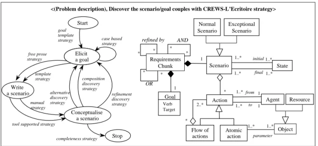
The method engineer selects the first chunk as a candidate one. However, as the requirements coverage is not fully adequate, he decides to apply the aggregation strategy (Figure 3) with the objective to find an aggregate chunk broader than this candidate chunk. Such a chunk exists; it is the L’Ecritoire chunk and its process and product parts are shown in Figure 7.
initial 1..* 1..* 1..* 1..* Exceptional Scenario Atomic action from to 1..* 1..* 1 1 * 2..* State final parameter 1..* 1..* Action Flow of actions refined by AND 1 1 * * * * OR * * Scenario Object * Goal Verb Target Agent Requirements Chunk Normal Scenario Resource Elicit a Use Case alternative discovery strategy composition discovery strategy Write a scenario Conceptualise a scenario template strategy free prose strategy
tool supported strategy manual strategy Start goal template strategy Elicit a goal refinement discovery strategy
completeness strategy Stop case based strategy
<(Problem description), Discover the scenario/goal couples with CREWS-L’Ecritoire strategy>
Figure 7 : The L'Ecritoire method chunk
This method chunk, called L’Ecritoire, provides guidelines to discover functional system requirements expressed as goals and to conceptualise these requirements as scenarios describing how the system satisfies the achievement of these goals [Rolland 98b], [Rolland 98c], [Tawbi 99]. Several different strategies are provided by the chunk to support goal elicitation, scenario writing and scenario conceptualisation.
The method engineer wants to get a quantitative evaluation of the fit of L’Ecritoire to the requirements map. Therefore, he selects the evaluation strategy (Figure 3) which helps him to compare the map of the candidate chunk with the requirements map. The map similarity measures SAI, SAS, SSI and PSSS presented in section 4.2.2 are used.
For example, owing to the SAI measure we detect that the intentions Elicit a requirement (requirements map) and Elicit a goal (L’Ecritoire map) are similar because they use the same verb and their targets requirement and goal are synonyms.
The measure SSI, calculated as follows :
SSI (Requirements map, L’Ecritoire map) = (2*2 similar intentions) / (6 intentions in two maps) = 2/3, shows that a large part of the requirements map is covered by the map of the
selected chunk. To validate this assumption, we search for similar sections by applying the SAS measure. For example, the SAS calculated as follows :
SAS (Requirements map : <Conceptualise a requirement, Elicit a requirement, Variants discovery strategy>, L’Ecritoire map : <Conceptualise a scenario, Elicit a goal, Alternative discovery strategy>) = 1, shows that the concerned sections are similar. Next, for
each couple of similar intentions we apply the PSSS measure to verify if the strategies between these intentions are also similar. For instance, the
PSSS (Requirements map : <Conceptualise a requirement, Elicit a requirement>,
L’Ecritoire map : <Conceptualise a scenario, Elicit a goal>) = (2* 2 similar strategies) / (6 strategies) = 2/3 shows that the map of the selected chunk matches a part of the requirements
map.
Figure 8 illustrates the matching of the map of the candidate chunk to a part of the requirements map. The degree of matching is satisfactory enough to select the candidate chunk.
Stop
Elicit a requirement
goal driven strategy
Document a requirement completeness strategy variants discovery strategy validation strategy linguistic strategy completeness discovery strategy Conceptualise a requirement linguistic strategy Start exceptions
discovery strategy Elicit a
Use Case alternative discovery strategy composition discovery strategy Write a scenario Conceptualise a scenario template strategy free prose strategy
tool supported strategy manual strategy Start goal template strategy Elicit a goal refinement discovery strategy
completeness strategy Stop case based strategy
Requirements map Map of the chunk L’Ecritoire
Figure 8 : Similarity measure between the requirements map and the L'Ecritoire map
The requirements coverage is not complete and the method engineer must continue the search. However, he knows the properties of the chunks he is looking for and can formulate precise queries. The required chunks must have the following values in their interfaces : situation =
goal or scenario, intention = to discover exceptional requirements (or goals).
The SAVRE method chunk [Sutcliffe 98], [Sutcliffe 99], [Maiden 98a], [Maiden 98b] presented in Figure 9 is one of the chunks retrieved by the query. This chunk provides guidelines to discover exceptions in the functioning of a system under design caused by human errors. It generates scenarios corresponding to the system requirements and identifies, through an analysis of these scenarios, possible exceptions caused by human errors (exception
discovery strategy). The chunk also includes validation patterns to validate the requirements
(validation patterns strategy).
Conceptualise a scenario automatic generation strategy Elicit a requirement Stop exception discovery strategy Start validation patterns strategy completeness strategy
<(Requirement, Use case), Elicit an exceptional requirement by analysing human errors> describes * 1 start 1..* 1..* Flow of events * Agent * Sequence Embedding Event Use case Scenario Requirement end Action 1 1 involves 1..* 1..* generates 1..* 1 Object uses *..1 1..*
Figure 9 : The SAVRE method chunk
The matching measures convinced the method engineer to make the decision to assemble the two selected method chunks, thus to move in the map of Figure 3 to Assemble chunks. The two chunks have the same broad objective, to discover system requirements, and their process and product models overlap (they contain similar intentions and concepts). Thus, the
Following the integration map shown in Figure 4, the method engineer understands that he first needs to adapt the product and process models of the two chunks. It is only after the necessary terminological adaptations that he will be able to proceed to their integration. As an example, he selects the name unification strategy in the integration map (Figure 4) and changes the name of the intention Elicit a requirement in the SAVRE map into Elicit a goal by
applying the RENAME_INTENTION operator.
Then, he progresses to the construction of the integrated process model with the merge
strategy to integrate the two maps. He applies the MERGE_INTENTION operator on the couples of identical intentions. The merged intentions are represented in grey in Figure 10. By selecting the addition strategy in the integration map he adds the transformation strategy to the integrated map by applying the ADD_SECTION operator. This new strategy permits the coupling of the two types of scenarios (the ones in L’Ecritoire and the ones in SAVRE) in the same integrated product. This adjunction is necessary to transform L’Ecritoire scenarios into
SAVRE scenarios and vice versa.
The integration of the two product models also requires some adaptations. For example, the two product models contain the scenario concept. The two scenarios have the same semantics, but their structures are different. L’Ecritoire scenarios are composed of a set of actions whereas SAVRE scenarios are defined as flows of events. The two kinds of scenarios must be kept in the integrated product model. Thus, the method engineer renames the scenario concept in the L’Ecritoire product model into L’Ecritoire scenario and in the SAVRE into SAVRE
scenario. The engineer selects the generalisation strategy in the integration map to integrate
the two scenario concepts by applying the GENERALISE operator. This leads to the introduction of a new concept scenario as a generalisation of the two concepts L’Ecritoire
scenario and SAVRE scenario in the integrated model. The notion of the Agent is the same in
the two product models. Thus, the merge strategy can be selected in the integration map to
help applying the MERGE_CONCEPT operator on these two concepts.
The result of the integration of L’Ecritoire and SAVRE method chunks is illustrated in Figure 10. initial 1..* 1..* 1..* 1..* Exceptional Scenario Atomic action from to 1..* 1..* 1 1 * 2..* State final parameter 1..* 1..* Flow of actions refined by AND 1 1 * * * * OR * * Object * Goal Verb Target Agent Requirements Chunk Normal Scenario Resource describes * 1 start 1..* 1..* Flow of events * * Event Requirement end 1 generates 1..* 1 Action Scenario SAVRE Scenario L’Ecritoire Scenario Use case Elicit a Use Case alternative discovery strategy composition discovery strategy template strategy free prose strategy tool supported strategy manual strategy goal template strategy Elicit a goal refinement discovery strategy completeness strategy Stop case based strategy Start exception discovery strategy automatic generation strategy transformation strategy validation patterns strategy Write a scenario Conceptualise a scenario
The requirements coverage is still not completed and the method engineer continues the search for chunks that can fill in the gap between the requirements map and the integrated chunk. There is a need for validating the requirements. Thus, the method engineer formulates a new query asking for chunks with the intention to validate the requirements in their interface. Among the retrieved method chunks, the method engineer retrieves the Albert method chunk [Heymans 98], [Dubois 98] presented in Figure 11.
Stop Start Conceptualise an Albert Spec. animate elicited scenarios strategy conflict resolution strategy consolidation strategy selection strategy Construct an animation trace template based strategy tool based strategy free animation strategy animate unwanted scenarios strategy
<(Scenario, Requirement), Validate requirement with the animation strategy>
describes characterised by has 1..* 1 1..* Agent Nom * Society Constraint Basic Constraint Local Constraint Co-operation Constraint Action State modifies 1..* 1..* 1 1..* 1..* 1
Figure 11 : The Albert method chunk
This chunk proposes guidelines to validate requirements in an animated manner. It can transform scenarios describing requirements into an Albert specification and then, supports the animation of these scenarios by activating the tool called Animator. The animation is interactive and the requirements stakeholders can validate the requirements.
Since this method chunk uses a scenario as a source product and validates the requirements expressed in this scenario, the process reaches a situation where the Albert chunk complements the current integrated chunk. In order to assemble this chunk with the current chunk assembly, the method engineer selects the association strategy in the assembly map (Figure 3). The guideline supporting the assembly by association was presented in 4.4.
The maps of the two chunks to assemble do not have similar intentions. Thus, there is no need to adapt the maps before their association. The method engineer selects the connection
strategy in the association map (Figure 5) and progresses to the construction of the associated
process model. Following the guideline associated to this section, he identifies that the achievement of the intention Conceptualise a scenario in the integrated map constructs a product (a scenario) which is a source product for the Albert chunk. The operator
MERGE_INTENTION is used on the intention Conceptualise a scenario and the Start
intention of the Albert map.
Some refinements are necessary on the associated map. For example, it seems reasonable to forbid a progression from the intention Conceptualise a scenario to Stop. By selecting the
remove strategy in the association map (Figure 5) and following the associated guideline, the
method engineer applies the operator REMOVE_SECTION on this section.
To construct the associated product model, the method engineer needs to perform some adaptation process. For example, both product models (the one of the method under construction and the one of the Albert chunk) contain the Agent concept. The two concepts have the same semantic but their structures are different. Therefore, it is necessary to rename
one of two concepts by applying the RENAME_CONCEPT operator. The method engineer decides to rename the Agent of the Albert chunk into Albert_Agent. The same operator must be applied on the State and Action concepts.
Then, the method engineer select the addition strategy (Figure 5) which allows him to add a link of the correspondence between the concepts Agent and Albert_Agent .
The end result is shown in Figure 12..
initial 1..* 1..* Atomic action from to 1..* 1 * 2..* State final parameter 1..* 1..* Flow of actions refined by AND 1 1 * * * * OR * * Object * Goal Verb Target Agent Requirements Chunk Normal Scenario Resource describes * 1 start 1..* 1..* Flow of events * * Event Requirement end 1 generates 1..* 1 Action Scenario SAVRE Scenario L’Ecritoire Scenario Use case describes 1..* Constraint Basic Constraint Local Constraint Co-operation Constraint characterised by has 1..* 1 * Society Formal Action Agent_State modifies 1..* 1..* 1 1..* Albert_Agent corresponds to Exceptional Scenario 0..1 1 Elicit a Use Case alternative discovery strategy composition discovery strategy template strategy free prose strategy tool supported strategy manual strategy goal template strategy Elicit a goal refinement discovery strategy case based strategy Start exception discovery strategy automatic generation strategy transformation strategy validation patterns strategy Write a scenario Stop animate elicited scenarios strategy conflict resolution strategy consolidation strategy selection strategy Construct an animation trace template based strategy tool based strategy free animation strategy animate unwanted scenarios strategy Conceptualise a scenario Conceptualise an Albert Spec.
Figure 12 : The end result of the chunk assembly
In a similar manner the selection of additional chunks to cover the entire requirements map and their assembly with the current integrated chunk will continue till the completeness strategy ensures that the result is satisfactory enough to stop the assembly process.
6
Conclusion
In this paper we look at situational method engineering from a process perspective and propose two embedded generic models to support :
- method construction, and
- method chunk assembly.
Both are concerned with engineering methods matching a set of requirements through a method chunk assembly technique. The former deals with assembly ‘in the large’ whereas the latter offer solutions ‘in the small’.
The process models are represented as maps with associated guidelines. This allows us to offer flexibility to the method engineer for carrying out the engineering activity. Besides, guidelines provide a strong methodological support, thanks to some formally defined techniques. Metrics to evaluate the distance between two method chunks and a set of operators to perform the assembly tasks are the two most important techniques.
The approach is currently used in a professional environment in the context of a rather large project (§10 millions). Results are encouraging, the experience is positive, even if it highlights the need for improvements among which is a software environment to support the process.
References
[Benjamen 99] A. Benjamen, Une Approche Multi-démarches pour la modélisation des démarches méthodologiques. Thèse de doctorat en informatique de l'Université Paris 1, 6 octobre 1999. [Besançon 99] R. Besançon, M. Rajman, J.C. Chappelier, Textual Similarities on a Distributional Approach.
Proceedings of the 10th International Workshop on Database and Expert Systems Applications (DEXA’99), Florence, Italy, September 1999.
[Bianco 99] G. Bianco, V. De Antonellis, S. Castano, M. Melchiori, A Markov Random Field Approach for Querying and Reconciling Heterogeneous Databases. Proceedings of the 10th International Workshop on Database and Expert Systems Applications (DEXA’99), Florence, Italy, September 1999.
[Brinkkemper 98] S. Brinkkemper, M. Saeki, F. Harmsen, Assembly Techniques for Method Engineering. Proceedings of the 10th Conference on Advanced Information Systems Engineering, CAiSE’98. Pisa Italy, 8-12 June, 1998.
[Castano 92] S. Castano, V. De Antonellis, B. Zonta, Classifying and Reusing Conceptual Schemas. Proceedings of the 11th International Conference on Conceptual Modeling (ER’92), pp. 121-138, Karlsruhe, 1992.
[Castano 93] S. Castano, V. De Antonellis, A Constructive Approach to Reuse of Conceptual Components. Proceedings of Advances in Software Reuse : Selected Papers from the Second International Workshop on Software Reusability, Lucca, Italy, March 24-26, 1993. R. Prieto-Diaz,W.B. Frakes (Eds), IEEE Computer Society Press.
[Diamantini 99] C. Diamantini, M. Panti, A Conceptual Indexing Method for Content-Based Retrieval. Proceedings of the 10th International Workshop on Database and Expert Systems Applications (DEXA’99), Florence, Italy, September 1999.
[Harmsen 94] A.F. Harmsen, S. Brinkkemper, H. Oei, Situational Method Engineering for Information System Projects. In Olle T. W. and A. A. Verrijn Stuart (Eds.), Mathods and Associated Tools for the Information Systems Life Cycle, Proceedings of the IFIP WG8.1 Working Conference CRIS'94, pp. 169-194, North-Holland, Amsterdam, 1994.
[Harmsen 97] A. F. Harmsen, Situational Method Engineering. Moret Ernst & Young , 1997.
[Heymans 98] P. Heymans, E. Dubois, Scenario-Based Techniques for Supporting the Elaboration and the Validation of Formal Requirements. Requirements Engineering Journal, Vol. 3, No. 3-4, 1998.
[Dubois 98] E. Dubois, P. Heymans, Scenario-Based Techniques for supporting the Elaboration and the Validation of Formal Requirements, Submitted to RE Journal, 1998.
[Jarke 99] M. Jarke, C. Rolland, A. Sutcliffe, R. Domges, The NATURE requirements Engineering. Shaker Verlag, Aachen 1999.
[Jilani 97] L.L. Jilani, R. Mili, A. Mili, Approximate Component Retrieval : An Academic Exercise or a Practical Concern ? Proceedings of the 8th Workshop on Istitutionalising Software Reuse (WISR8), Columbus, Ohio, March 1997.
[LPR95] Le Petit Robert, French Dictionary, Dictionnaires LE ROBERT, France,1995.
[Maiden 98a] N.A.M. Maiden, CREWS-SAVRE: Scenarios for Acquiring and Validating Requirements. Journal of Automated Software Engineering, 1998.
[Maiden 98b] N.A.M. Maiden, S. Minocha, K. Manning, M. Ryan , SAVRE: Systematic Scenario Generation and Use. International Requirements Engineering Conference (ICRE’98), Colorado Springs, Colorado, USA, April 6-10, 1998.
[Papadopoulos 99] A.N. Papadopoulos, Y. Manolopoulos, Structure-Based Similarity Search with Graph Histograms. Proceedings of the 10th International Workshop on Database and Expert Systems Applications (DEXA’99), Florence, Italy, September 1999.
[Plihon 96] V. Plihon, Un environnement pour l'ingénierie des méthodes, Thèse de doctorat de l'Université Paris 1, janvier 1996.
[Plihon 98] V. Plihon, J. Ralyté, A. Benjamen, N.A.M. Maiden, A. Sutcliffe, E. Dubois, P. Heymans, A Reuse-Oriented Approach for the Construction of Scenario Based Methods. Proceedings of the International Software Process Association's 5th International Conference on Software Process (ICSP'98), Chicago, Illinois, USA, 14-17 June 1998.
[Poels 00a] G. Poels, G. Dedene, Distance-based software mesurrement : necessary and sufficient properties for software measures. Information and Software Technology, 42, pp. 35-46, 2000.
[Poels 00b] G. Poels, S. Viaene, G. Dedene, Distance Mesure for Information System Reengineering. Proceedings of the 12th Conference on Advanced Information Systems Engineering CAISE’00, Stockholm, Sweden, June 2000.
[Punter 96] H.T. Punter, K. Lemmen, The MEMA model : Towards a new approach for Method Engineering. Information and Software Technology, Vol. 38, No.4, pp.295-305, 1996.
[Ralyté 99a] J. Ralyté, C. Rolland, V. Plihon, Method Enhancement by Scenario Based Techniques. Proceedings of the 11th Conference on Advanced Information Systems Engineering, Heidelberg, Germany, June 14-18, 1999.
[Ralyté 99b] J. Ralyté, Reusing Scenario Based Approaches in Requirement Engineering Methods: CREWS Method Base. Proceedings of the First International Workshop on the Requirements Engineering Process - Innovative Techniques, Models, Tools to support the RE Process, Florence, Italy, September 1999.
[Ralyté 01] J. Ralyté, Ingénierie des méthodes par assemblage de composants. Thèse de doctorat en informatique de l'Université Paris 1. A paraître en janvier 2001.
[Rolland 95] C. Rolland, C. Souveyet, M. Moreno. An Approach for Defining Ways-Of-Working, in the Information Systems Journal, 1995.
[Rolland 96] C. Rolland, N. Prakash, A proposal for context-specific method engineering, IFIP WG 8.1 Conference on Method Engineering, Chapman and Hall, pp 191-208, Atlanta, Gerorgie, USA, 1996.