HAL Id: hal-01590876
https://hal.inria.fr/hal-01590876
Submitted on 20 Sep 2017
HAL is a multi-disciplinary open access
archive for the deposit and dissemination of
sci-entific research documents, whether they are
pub-lished or not. The documents may come from
teaching and research institutions in France or
abroad, or from public or private research centers.
L’archive ouverte pluridisciplinaire HAL, est
destinée au dépôt et à la diffusion de documents
scientifiques de niveau recherche, publiés ou non,
émanant des établissements d’enseignement et de
recherche français ou étrangers, des laboratoires
publics ou privés.
Distributed under a Creative Commons Attribution| 4.0 International License
Scenarchitectures: The Use of Domain-Specific
Architectures to Bridge Design and Implementation
Nicholas Graham, Emmanuel Dubois, Christophe Bortolaso, Christopher
Wolfe
To cite this version:
Nicholas Graham, Emmanuel Dubois, Christophe Bortolaso, Christopher Wolfe. Scenarchitectures:
The Use of Domain-Specific Architectures to Bridge Design and Implementation. 13th International
Conference on Human-Computer Interaction (INTERACT), Sep 2011, Lisbon, Portugal. pp.341-358,
�10.1007/978-3-642-23771-3_26�. �hal-01590876�
Scenarchitectures: The Use of Domain-Specific
Architectures to Bridge Design and Implementation
Nicholas Graham2, Emmanuel Dubois1, Christophe Bortolaso1, Christopher Wolfe21 IRIT, University of Toulouse, 31000 Toulouse, France
{Emmanuel.Dubois, Christophe.Bortolaso}@irit.fr
2 School of Computing, Queen’s University
Kingston, Ontario, Canada K7L 3N6 {graham, wolfe}@cs.queensu.ca
Abstract. In this paper, we present scenarchitectures, a means of raising the
level of design of advanced interactive systems. Scenarchitectures combine elements of scenarios and system architectures, and can be used during the user interface design process as an adjunct to other design tools such as textual scenarios and story boards. Meanwhile, scenarchitectures can be automatically transformed to system architectures, providing a link between design and implementation. Using two existing scenarchitectural notations, we investigate the role of scenarchitectures in the design process. We then show how model-transformation techniques can be used to automatically derive system architectures from scenarchitectures, and conclude with concrete examples of the application of the scenarchitectural approach to the design of a mixed-reality system.
Keywords: User interface design methods, software architecture,
scenarchitecture, adaptive groupware, mixed interactive systems.
1 Introduction
As interest increases in novel forms of interaction such as mobile applications, groupware and mixed reality, developers face an ever-growing gulf between design and implementation. For example, groupware developers must solve low-level distribution issues such as replica consistency management and partial failure, while developers of mixed-reality applications face technical issues such as real-time object recognition and pose detection. These hard implementation issues detract focus from the design of the application, and form a barrier to iterative user interface refinement.
In this paper, we present the notion of scenarchitectures, an emerging technique bridging the gap between design and implementation of advanced interactive systems. Scenarchitectures capture aspects of an application’s architecture, but expressed as a scenario. Scenarchitectures can therefore be used during the interaction design process as an adjunct to other design tools such as textual scenarios, story boards and task models [8]. Meanwhile, scenarchitectures can be automatically transformed to implementation architectures, providing a link between design and implementation.
Fig. 1. The gulf between the scenario view used by designers and the architectural
view of implementers (adapted from Carroll [7]).
Scenarchitectural styles are domain-specific. For example, ASUR helps in the design and implementation of mixed reality applications [15], while Fiia is customized for mobile groupware applications [24]. By focusing on a single domain, a scenarchitectural style can provide abstractions and implementation techniques tailored to that domain, while retaining a simple and easily learned syntax.
Fiia and ASUR were developed separately, but share core concepts. In this paper, we use these two styles to illustrate the principles underlying scenarchitectures. We show how Fiia and ASUR support a common process, and show how their differences help to illustrate different aspects of the design space of scenarchitectural styles.
We first survey the traditional relationship between scenario-based design artifacts and software architectures, illustrating the ever-widening gulf between design and implementation. We then introduce the concept of scenarchitectures, illustrated by our two examples of Fiia and ASUR. We explore how scenarchitectures fit within a design process, showing how they can be derived from scenarios, and how they can coevolve with interaction design artifacts during iterative refinement. Finally, we discuss how model transformation techniques can be used to automatically map scenarchitectures to implementation-level system architectures.
2 Traditional Approach
There is increasing recognition of the significant gulf between the perspectives of designers and implementers of interactive systems [6,4]. This gulf is illustrated by two widely-used design notations: scenarios and software architectures. Scenarios are, according to Carroll ―a narrative description of what people do and experience as they try to make use of computer systems and applications‖ [6]. Scenarios aid design by capturing how people use existing systems [3], and how they might use new systems. Scenarios may be expressed textually, using storyboards, or through video [19]. Software architectures, on the other hand, are a central design artifact used to document a system’s implementation [2]. They show how the system is decomposed into components and how these components interact. Numerous software architectural styles have been proposed for interactive systems, such as MVC [17] and PAC [9], and more recently special purpose architectures for groupware [11] and games [13].
These two examples capture what Carroll calls the scenario and establishment perspectives in software design [7] (figure 1), showing the differing perspectives of designers and implementers. Concrete examples become generic and abstract; instead of focusing on the user’s experience, the implementation focuses on the
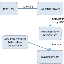
Fig. 2. Fitting scenarchitectures into the development process.
system-level components that implement the interaction; scenarios cover part of the system’s use, while an architecture must comprehensively specify a complete design; scenarios are typically written in imprecise, free-form prose, while architectures are specified in a well-defined and precise notation; and scenarios express the expected (or ―envisioned‖) use of the system, while architectures are specifications. These multiple changes in perspective cause the difficulty of moving from interaction design to implementation design.
An alternative to the ―traditional‖ approach is the model-based generation of user interfaces from high-level models. These approaches are mainly based on task models, as following the CAMELEON framework [5]. As opposed to scenario-based design, generation of user interfaces from task models has largely been confined to the research lab. We argue in the following sections for a new approach, scenarchitectures, which combine aspects of scenarios and system architectures.
3 Overview and Examples
Scenarchitectures are design-level documents written from the system perspective. They provide a notation that can be used in design sessions alongside traditional scenarios, user interface mockups and task models. Scenarchitectures contribute to iterative design by helping to make the design more concrete, and provide a bridge towards the implementation of an interactive system.
Figure 2 shows how scenarchitectures fit into a design and development process. Scenarios capture how people interact with the system under design. Scenarchitectures make these scenarios more concrete by capturing the system’s components, relations between the components, and techniques used by the user to interact with the system. Scenarios and scenarchitectures are complementary:
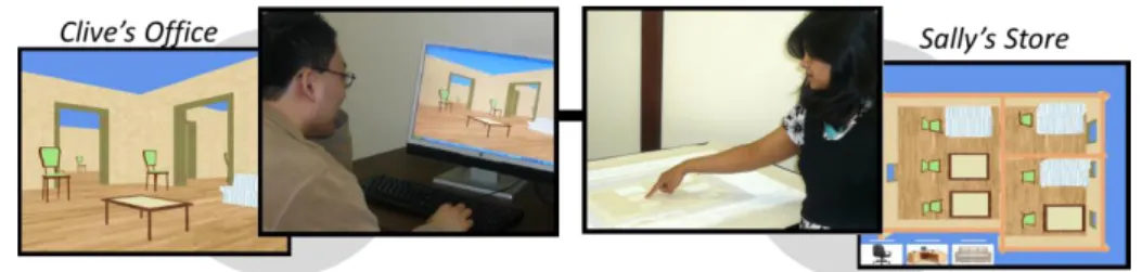
Fig. 3. Furniture layout application – ―Sally‖ the salesperson lays out furniture on a
tabletop, while ―Clive‖ the customer sees the results in 3D on his PC.
scenarios suggest system structures that should be captured in scenarchitectures; scenarchitectures in turn identify areas where scenarios are missing or lacking in detail. As we will show, scenarchitectures help with implementation, as model-driven engineering techniques can be used to transform scenarchitectures to system architectures.
Scenarchitectures are diagrammatic notations capturing a conceptual view of an interactive system in the context of its use. Three defining features of scenarchitectures differentiate them from traditional software architectures as described using class diagrams:
Scenarchitectures are concrete. As opposed to a class diagram which expresses the relationships between types of components, scenarchitectures show the actual instantiated components making up the system;
Scenarchitectures are runtime snapshots showing the system at a particular point during the interaction. A scenario might be explained via a sequence of scenarchitectural diagrams, where each diagram captures a significant situation expressed by the scenario;
Scenarchitectures are domain-specific, specialized to the type of scenario being expressed.
We now provide two examples of scenarchitectural styles, and discuss how they can be used to support the design of mixed-interactive systems and adaptive groupware systems. We draw two examples of scenarchitectures from the literature: ASUR [15] and Fiia [24]. Both are domain-specific, with ASUR targeted towards mixed-interactive systems, and Fiia supporting the design of adaptive groupware. While both ASUR and Fiia already existed, our framework helps show the commonality of their approach and illustrates the tradeoffs they make. We briefly describe these scenarchitectural styles, and then show how they can be used to support both the interaction design process and the model-based derivation of traditional software architectures.
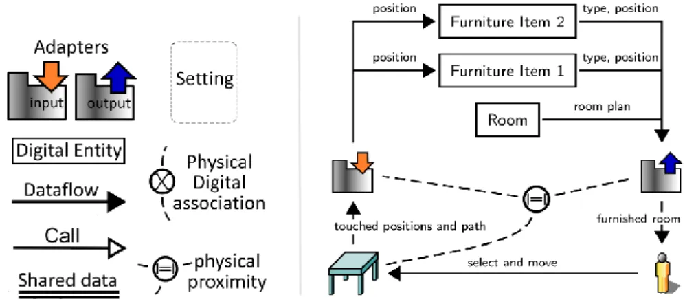
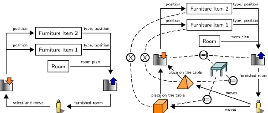
To illustrate these two styles, we use the scenario of a tool helping with the layout of furniture in an office (figure 3.) ASUR and Fiia use different notations. To simplify presentation, we use a subset of their notations, in a unified syntax. This is summarized in figure 4 (left).
Fig. 4. Left: Legend showing scenarchitectural notation, and right: an ASUR
scenarchitecture showing how ―Sally‖ the salesperson manipulates digital furniture on a physical tabletop.
3.1 Example: The ASUR scenarchitectural model
ASUR helps bridge between design and implementation of mixed-interactive systems. Such systems seamlessly combine the physical and virtual worlds. To help ―Sally‖ explore the layout of furniture, the application of figure 3 displays digital images of the furniture on a physical table. Sally touches and drags furniture items to move them around the room.
ASUR scenarchitectural diagrams, such as the one shown in figure 4, capture snapshots of such mixed-interactive systems. Figure 4 (right) shows the table, digital furniture and digital map of the rooms. Adapters detect ( ) which furniture item is touched by the user on the table, and project ( ) the furniture layout on the table. Dataflow arcs express that the ―User‖ selects and moves an item projected on the table, which in turn conveys a position and motion path to the input adapter, which finally delivers a position to the relevant ―Furniture Item‖ before rendering it through the output adapter. Finally, the diagram specifies that the table, input and output adapters are all physically close (|=|) to the presenter.
ASUR diagrams therefore capture the components of a system at a conceptual level, showing the system’s configuration at a particular point in time. ASUR is a domain-specific notation, tuned to answering questions pertinent to mixed interaction, and eliding details less relevant to that domain. As we shall see, this allows models to be created quickly and fluidly, allowing their use in design sessions.
ASUR diagrams can be created at several levels of detail. When hand-sketched during a design meeting, details such as dataflow types are typically omitted. The model can be refined as part of the process of moving towards implementation. Also as part of the implementation process, decisions must be made such as how the input adapter should be implemented (e.g., as a camera tracking fiducial markers on the fingers, or via capacitive touch.)
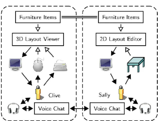
Fig. 5. A Fiia scenarchitecture showing how a salesperson and customer
collaborate in the furniture layout task.
ASUR scenarchitectural diagrams provide a bridge to implementation. Using the Guide-Me tool [14], an ASUR scenarchitecture can be semi-automatically transformed into an implementation architecture, where code stubs are provided for virtual components, and where adapters are automatically implemented [15].
3.2 Example: The Fiia scenarchitectural model
Fiia addresses the problem of developing adaptive groupware systems – systems that allow groups of people to work together, and that adapt to changes in users’ tasks, locations and devices. Figure 5 continues our furniture layout example, showing how salesperson ―Sally‖ creates a furniture layout for a customer ―Clive’s‖ office. Sally uses a tabletop surface to manipulate furniture in a top-down view. Meanwhile Clive uses a 3D viewer to see how the furniture will appear in his office.
Fiia captures the implementation design of groupware applications. The diagram of figure 5 shows the two participants’ settings (demarcated by dashed lines), emphasizing the different contexts of the collaborators. The ―=‖ line shows data that is shared by Sally and Clive (the furniture layout – what furniture items are being used, and where they are located). Sally interacts with the furniture layout using a ―2D layout editor‖, which she manipulates via a tabletop surface. Meanwhile, Clive can view the scene on his PC using a ―3D layout viewer‖.
Fiia is domain-specific in that it provides high-level constructs directly addressing groupware concepts. Settings collect people and their resources; sharing shows what resources are accessible to different users, and adapters (as in ASUR) explicitly show the devices that people use to interact with the system.
Fiia diagrams represent a snapshot of the system’s use at a single point in time. As we shall see, a sequence of Fiia diagrams can be used to capture the flow of changing tasks, locations and devices, each showing the transition from one situation to another.
Fig. 6. How scenarchitectures bridge design and implementation.
Fiia diagrams are usable not just to clarify the system’s design, but also as runtime artifacts used in the system’s implementation. Through a model transform algorithm [25], Fiia diagrams are automatically transformed to distribution architectures, suitable for direct execution. Both the Fiia model and the distribution model are maintained at runtime, and changes to either are automatically reflected in the other. This enhances the value of the Fiia diagrams, as they not only help clarify design, but provide a significant step towards implementation.
ASUR and Fiia serve as strong examples of scenarchitural styles, showing how scenarchitectures expressed using these styles are concrete, runtime, domain-specific and help lead to implementation via model transformation.
In the following two sections, we explore how scenarchitectures support design through their close linkage to scenarios, and how scenarchitectures provide a bridge to implementation through model-based derivation of system architectures. We then provide an example showing how ASUR has been used in an end-to-end design and implementation process.
4 Scenarchitectures in the Design Process
As we saw in figure 1, Carroll has identified the ways in which scenarios provide a different perspective on systems than the traditional architectural view. We now expand this to figure 6 to show how scenarchitectures are compatible with scenario-level design and also serve as a bridge to implementation. As motivated by Hornecker [16], this approach of combining formal representations and design sessions is part of a larger design approach in which participants’ creativity benefits from the generative power [22] of design models.
As with scenarios (and unlike system architectures), scenarchitectures are concrete and focused on instances. This is the fundamental reason why they are an appropriate tool within scenario-based design. For a given step in a scenario, a corresponding scenarchitecture can be created, showing the system’s components. This helps situate the scenario in terms of the system being manipulated. When a user action is described in a scenario, the action can be clarified through the scenarchitecture – it is possible to see the instruments that the user will be manipulating, and trace the effects of these manipulations through the system. This view complements that of the scenario itself, which better captures the user’s intentions, deliberations and mood. Because they are at the same level, designers can use both forms of description. Elaboration of one artifact may expose open questions in the other, leading to a coevolutionary refinement of both.
Meanwhile, scenarchitectures form a bridge between design and implementation. Scenarios are work-driven (expressing users’ actions and intentions) while system architectures are technology-driven (illustrating the system’s software and hardware components), and scenarchitectures have elements of both (showing the system’s components and how the user interacts with them).
Scenarchitectures typically start their life during brain-storming sessions as open-ended and fragmentary and are later refined to a complete and exhaustive state necessary for model-based implementation. Using scenarchitectures during a design session thus supports progressive movement from a very partial description, such as those offered with scenario, to a complete description of the solution including implementation recommendations as those included in architectural models.
Scenarchitectures are also refined to bridge the gap between informality and formality: their use is flexible enough to allow discussions among non-experts but they also conform to a formal meta-model.
Finally, scenarchitectures constitute specified solutions. Each scenarchitecture diagram describes how the system will work and how the user will interact with it. Scenarchitectures are not limited to an envisioned use as in the case of scenarios.
We have identified four ways in which scenarchitectures help in the design process: supporting exploration and better understanding of tasks; refining scenarios from abstract to concrete; illustrating alternative ways of carrying out a task, and illustrating the steps of a scenario. We now illustrate these using examples from ASUR and Fiia.
4.1 Support Exploration of Tasks
Scenarchitectures help designers explore users’ tasks. They help in the refinement of both task and scenario descriptions by providing a different viewpoint on the interaction and by helping to clarify how the user interacts with the system itself.
If we consider our furniture layout example, we might state the initial task as ―find appropriate furniture and layout for an office‖. The Fiia scenarchitectural diagram of figure 5 encourages us to think about a range of questions related to the task:
What are the roles of the different participants? Sally is trying to sell furniture, and therefore her task is ultimately to find a furniture configuration that Clive is willing to purchase. Meanwhile, Clive’s ultimate task is to assess how well Sally’s proposals will fit his office.
How do the participants interact with the system? To support her sales role, Sally will propose ideas for furniture and how it will be laid out. She therefore needs an editor allowing her to quickly manipulate the furniture. The editor provides a top-down view, and is based on a touch-surface where furniture can be easily dragged and rotated. Meanwhile, Clive might have a harder time understanding the abstract top-down view, and therefore sees the furniture in 3D, as will appear in the office. The Fiia diagram clarifies Clive’s use of a standard PC, where a mouse and keyboard are used to navigate the 3D scene, while Sally uses a specialized tabletop computer to manipulate the furniture positions.
Fig. 7. Abstract ASUR description of the furniture layout (left) and concrete
description of tangible interface (right).
How do the participants communicate with each other? The Fiia diagram clearly illustrates the participants’ points of communication. The furniture layout data is shared, and therefore Clive’s view is updated in real time in response to Sally’s edits. Both Sally and Clive share a voice over IP connection allowing speech communication.
The process of creating the Fiia diagram helps to address these questions, simply because the diagram explicitly contains the participants’ settings, devices and communication modalities. Creating the diagram therefore raises questions that designers must consider, helping to refine understanding of the underlying task. Scenarchitectural diagrams are complementary to traditional task models. If the design process uses task models, formalized links can be established between them and scenarchitectures [8].
4.2 Refine Scenarios from Abstract to Concrete
The design of an interactive system is often initially sketched in an abstract form, where details are left for later discussion. Scenarchitectures support this transition from abstract to concrete form. This allows designers to work with a level of abstraction that is appropriate to the stage of the design process. We illustrate this refinement by example.
Our example system allows the seller to move furniture items within a digital representation of the customer’s office. As shown in figure 7 (left), ASUR can be used to provide a concise description of this very abstract definition of the system: ASUR entities represent the key concepts, and the ASUR arrows depict the communication channels required to perform the features. This abstract description however does not help designers understand the concrete specifics of interaction. The furnished room might for example be displayed on a screen or described via spoken voice. Scenarchitectures help refine such abstract scenarios to concrete designs.
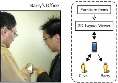
Fig. 8. Customer ―Clive‖ moves to his boss’ ―Barry’s‖ office and shows him his
furniture purchase decisions.
One design option would be to provide a speech interface for the ―select and move‖ action. As a result, the input sensor would have to be able to recognize speech. An alternative design would be to add a table in the seller’s interaction space, as was seen in figure 4 (left). These items are then displayed by a device that is physically grouped (|=|) with the table and the sensor. Attributes of the communication channels between the table and sensor express that the touched position on the table are encoded in an IR Image (not shown), implying that the sensor must be an IR Camera. This concrete refinement is illustrated in figure 4 (right).
This refinement within the scenarchitectural notation matches the needs of the design process. Designers can start with their choice of abstract or concrete design, and refine over the course of their design session, all within the same notation. The scenarchitectural diagram helps identify areas where decisions need to be made more concrete, helping to feed back into the design.
4.3 Illustrate Alternative Ways of Carrying out a Task
An important part of ideation is rapid consideration of design alternatives. Scenarchitectural diagrams are high-level, tuned to a particular domain, and – as described in the last section – support refinement from abstract to concrete form. This makes them suitable for rapid sketching of alternative design ideas.
Figure 4 showed one concrete design of the furniture layout editor. A second option (figure 7, right) uses a physical representation of every furniture item: a cube represents a table; a pyramid stands for a chair, and a cone for a lamp. Placing or dragging these tokens moves virtual furniture items. This physical–digital association is represented by an ―X‖ symbol in the ASUR diagram. The localization of all
physical tokens on the table is performed through an input adapter, still tightly coupled with the projector and physical table.
To move from the digital tabletop solution (figure 4) to this tangible tabletop solution, the scenarchitectural diagram remains unchanged in its treatment of the digital world. The physical area, however, has been reworked to introduce new elements and correctly insert them in the interaction process.
This example illustrates how scenarchitectures support the brainstorming of different ideas within the design process, helping to quickly illustrate the system perspective of different design ideas.
4.4 Illustrate Scenario Steps
A scenario may involve changes to the system’s configuration, for example in response to new devices becoming available, users’ changing location, or partial failure of the underlying infrastructure. Such changes can be described as part of a prose scenario, and can also be precisely captured using a scenarchitectural diagram.
As a second step in our furniture layout scenario, Clive finishes his session with Sally, and wishes to discuss the results with his boss ―Barry‖. He walks to Barry’s office, and uses his Smartphone to show the resulting furniture layout. On the smaller screen device, he uses a top-down view (similar to the one Sally used on her tabletop display.) Using dragging and zooming operations, he explains the furniture purchase proposal to Barry. Figure 8 shows the Fiia diagram capturing this scenario step.
This example shows how scenarchitectural diagrams can capture the steps involved in a scenario. In this case, the following has changed:
The participants: Sally has left the collaboration, while Barry has joined;
The participants’ settings: the collaboration is now co-located (in Barry’s office) rather than distributed;
The participants’ devices: instead of the PC and tabletop, the participants are now using a Smartphone;
The task: the task has moved from finding a furniture layout to trying to convince the boss to release funds to proceed.
Real collaborative work typically involves such changes in participants, tasks, locations, devices and collaboration style. Scenarios are an excellent tool for documenting such changes. Because they express particular instances, scenarchitectures are suitable for capturing the the steps identified in a scenario. They add to the information in the scenario by explicitly showing changes in participants, settings and devices in response to changes in the task.
4.5 Summing up: Fitting scenarchitectures into the design process
In this section, we have shown how scenarchitectures can contribute to the design of richly interactive systems such as adaptive groupware and mixed interactive
systems. We have discussed how scenarchitectures can help refine the designers’ understanding of tasks, how they can help transition from abstract to concrete designs, how they can help enumerate design choices, and how they can help show transitions in the system’s user’s tasks, devices and locations. By supporting these activities, scenarchitectures can be refined together with other design artifacts such as task descriptions and textual scenarios.
Scenarchitectures are better suited to this role than traditional software architectures due to their high-level and user-focus. Returning to the table of figure 6, a fundamental property of scenarchitectures is that, like scenarios, they are concrete and focus on particular instances. This allows direct matching of system entities with the activities described in scenarios. In effect, the steps of a textual scenario act as captions describing the situations diagrammed in a scenarchitecture.
Scenarchitectural diagrams bridge the gaps of formality and rigor. Diagrams can be informally sketched on a whiteboard or paper. As part of the process of moving to an implementation, they can later be refined to clean up their syntax or add detail.
More fundamentally, moving from a scenarchitecture to a concrete implementation requires movement from the scenarchitecture’s concrete and instance-focused representation to the software architecture’s abstract and generic representation. As we will discuss, model transformation techniques can partially (or fully) automate this process. We argue that this automation is crucial to the practicality of the scenarchitectural approach, by providing developers with a concrete implementation benefit in addition to the less tangible benefits of improvement of the design process.
5 Deriving Implementations from Scenarchitectures
The key to the practical use of scenarchitectures is the ability to automatically derive all or part of the system architecture from the scenarchitectural descriptions (figure 2). This provides a seamless transition from the world of design to the world of implementation. It also adds significant value to the scenarchitectures themselves, as they not only aid in design, but also provide a gateway to implementation.
The generation of system architectures from scenarchitectures is a model-transformation problem [20]. How this is done in ASUR and Fiia is described in detail elsewhere [14,25], but we briefly summarize their approaches. In Fiia, the system architecture contains the same components as the Fiia diagrams [24]. Adapters are replaced by components that interface with the specified devices. Connectors are replaced with system-level components that provide network endpoints, caches, broadcasting facilities, and concurrency-control and consistency maintenance managers. The Fiia runtime is responsible for dynamically modifying this system architecture in response to change from one Fiia diagram to another (as described in section 4.4) [25]. Fiia produces only architectures, not complete programs; developers are responsible for programming the internals of the components in their Fiia diagrams. The Fiia runtime architectures are highly performant, executing faster than architectures programmed in native code [24].
ASUR’s Guide-Me tool generates the part of the software architecture that is responsible for interaction [14]. Developers are responsible for integrating this
sub-architecture with their application. Guide-Me helps developers choose between different interaction technologies, and automatically generates device handling code over existing middleware. Interaction sub-architectures can be generated for each situation identified in an ASUR diagram, and can be manually linked.
As these two examples suggest, there is a significant tradeoff space in how scenarchitectures can be transformed to system architectures. ASUR and Fiia’s different points in this tradeoff space help to illustrate how different implementation choices are appropriate to different kinds of scenarchitectural style. We now enumerate the axes of this tradeoff space:
Development-time versus runtime models: The transformation from a source to target model may be a static process, where the scenarchitectures are used to create a system architecture. Alternatively, the transformation may be dynamically performed at runtime. ASUR’s Guide-Me tools take the static approach, with the advantage that it is considerably easier to implement [15]. This allows Guide-Me to use standard model transformation tools based on Eclipse’s ATL Transformation Language [18]. The dynamic approach, as used by Fiia, gives the additional flexibility of allowing the program to consult the state of the scenarchitecture as the program executes. This is necessary for adaptive groupware, where execution involves transition from one scenarchitecture to another. Runtime models have considerably stronger performance requirements: it is acceptable for a static transformation to take minutes to execute, while a dynamic transformation must typically be executed in milliseconds in order to avoid a perceptible pause in the application’s execution. Fiia uses a custom model-transformation algorithm to achieve runtime speeds in transformations [25].
Ability to edit at both levels: Typical model transformation techniques are one-way only, allowing a target model to be generated from a source model. Bidirectional transformations allow either level to be edited, and changes in one to be reflected in the other. ASUR uses a one-way transformation, meaning that if the transformation is executed again, any changes that have been made in the system architecture must be manually integrated into the newly generated architecture. With Fiia, bi-directional changes are supported through a novel rewriting transformation algorithm [25], allowing changes in the system architecture (e.g., due to partial failure in the distributed system) to be reflected in the scenarchitecture.
Degree to which implementation requires hand-coding to make it executable: The system architecture that results from the transformation must be populated with code to allow its execution. As discussed above, Fiia and ASUR require application components to be hand-coded.
Ability of developer/end-user to influence transformation: When the transformation is non-deterministic (i.e., multiple target models could result for a single source model), the transformation engine may not pick the best result. Different approaches exist allowing the developer to influence the transformation. Fiia uses semantics-preserving annotations on the source model, while ASUR engages the user during the transformation process.
Fig. 9. Screenshots of CladiBubble: a 3D cladogram and its digital bubble for grouping
species.
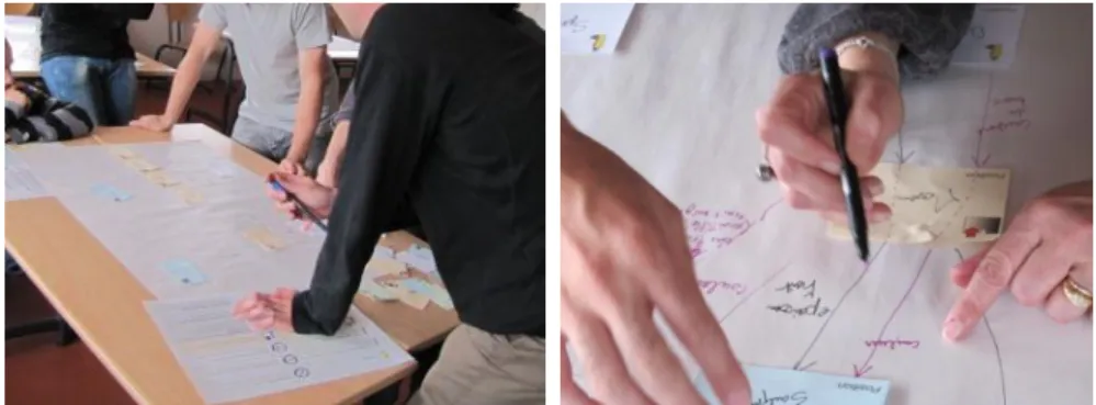
Fig. 10. The CladiBubble design team collaboratively creating an ASUR model.
In sum, ASUR uses classic forward engineering using standard tools, while Fiia is based on incremental, bi-directional runtime adaptation of models. The differences between the model transformation approaches taken by ASUR and Fiia show that a wide range of techniques are appropriate for different classes of architectural style. Specifically, forward engineering is a good match for ASUR, since the required transformation is from a static diagram to a system architecture. Forward engineering allows the use of stock tools (ATL) and allows an interactive generation process. Fiia, on the other hand, relies on transitions between scenarchitectures at runtime, and needs to support bidirectional transformation. This requires a novel transformation algorithm that can perform bidirectional updates at runtime speed. The tradeoff space that we have identified above helps to understand this range of implementation techniques for different kinds of scenarchitectural style.
6 Example of Collaborative Design using Scenarchitectures
We have used scenarchitectures to help design numerous concrete systems, including the furniture layout application described earlier in this paper [24] and the Raptor tool for game sketching [23]. To more concretely illustrate the concepts presented in this paper, we now explore our use of scenarchitectures in the development of CladiBubble, an augmented reality exhibit for the Toulouse Museum
of Natural History. CladiBubble is a walk-up exhibit that helps explain the cladistics biological classification system to museum visitors. Visitors are invited to manipulate a three-dimensional cladogram (i.e., tree of life) in order to modify the tree and move the species spatially close to each other. Then visitors are asked to group species (e.g. tree leaves) using a digital bubble (figure 9).
The CladiBubble design team was multi-disciplinary, involving a museologist, computer scientists, ergonomists and domain experts. Each design session was two hours in length. During the session, we used scenarchitectures in the ASUR style to augment traditional idea capture devices (i.e., post-it notes, whiteboards and mockups).
The core of the design session was an unconstrained iterative process of idea generation [22], diagramming the idea as an ASUR scenarchitecture, and exploring potential variations. Concretely, when a participant suggested an idea, he/she sketched it using ASUR (figure 10). Then the facilitator pointed out possible variations of relevant characteristics, helping the participants identify a new range of possibilities.
We observed that elementary manipulations of a scenarchitecture diagram during design sessions helped designers to systematically explore the design space, as suggested in section 4.3. For example, an early design for manipulating the digital species of the tree required users to manipulate blocks, each representing a species. An alternative design suggestion was to add a physical element to the grouping task (with the bubble). The designers created a physical balloon whose behavior is directly linked to the grouping bubble behavior (as illustrated by ASUR’s mixed proximity ―X‖ group). In both of these examples, scenarchitectural diagrams were helpful in exploring the design space and prompting designers to envision new possibilities.
We also observed that scenarchitectures eased the refinement of abstract system descriptions into concrete solutions (as suggested in section 4.2). For example, during the session a participant suggested the use of a remote pointer to select the species in the tree. He then added an input sensor to link his physical remote controller with the digital entities. At that point, the domain expert advised the group that wires were a poor choice in a museum context. As a result, the facilitator suggested the use of the light to convey information, leading the input adapter to be refined to an infrared camera. In this example, a domain constraint (i.e., wire-free environment) and an ASUR attribute drove participants to generate a new interactive solution. As a result, the scenarchitecture helped to refine an abstract attribute to a concrete solution.
By the end of the session, 17 different scenarchitectures had been generated. These models captured a range of generic interaction techniques, which we classified as: 1) remote pointers, 2) gesture and pen based interaction, 3) tactile tabletops and 4) tangible interfaces. For each of these generic techniques, participants explored several metaphors. For example, to inflate the bubble two metaphors were proposed: a physical inflatable balloon whose behavior was analogous to the digital bubble, and a pump for inflating the digital bubble.
This example of the design of CladiBubble illustrates how scenarchitectures assist in the exploration of the design space, and particularly highlights their usefulness in refinement of abstract attributes to concrete solutions, as well as showing their capacity for illustrating different ways of carrying out a defined task.
7 Discussion
This paper has introduced the concept of scenarchitectures as a notation bridging design and implementation. We have shown how designers can use scenarchitectures during design sessions, and how the resulting designs can be used as input to a model transformation process, helping to create a system architecture. We have discussed the space of model-transformation techniques helping the derivation of system architectures from scenarchitectural models. We have illustrated how two existing models fit with the concepts, roles and impacts of a scenarchitecture on the development process of advanced interactive systems – Fiia for adaptive groupware, and ASUR for mixed-interactive systems.
We have argued that scenarchitectural styles are by their nature domain-specific. An obvious question is whether it would be possible to create a single notation supporting interactive systems in general. Three points argue against this approach:
To be usable in design sessions, scenarchitectural styles should be simple, easily taught, easily used, and should address the specific issues that commonly occur in the design of a particular class of interactive system. For example, ASUR focuses on the design of the adapters that people use to interact with mixed-interactive systems, while Fiia focuses on how people interact with each other through shared artifacts and shared communication modalities. Attempting to address too many interactional issues in a single notation would conflict with the need for notational simplicity.
As discussed in section 5, ASUR and Fiia use very different approaches to generate system architectures. ASUR is based on static transformation involving interactive guidance from the developer. Fiia uses dynamic, bi-directional transformation at runtime to support real-time adaptation. A unified notation would make it difficult to support such varied implementation techniques.
Finally, as new styles of interaction are developed, it seems unreasonable to expect to anticipate all possible styles.
Relatedly, we might speculate about what kind of additional scenarchitectural styles could be interesting. A further example from the literature is MIM, which allows the development of mixed-interactive systems [10]. Another candidate where domain-specific notations might of use includes interfaces for the otherly-abled (allowing exploration of how an application might present interaction possibilities to people with a range of disabilities). Much future research is possible to find further domains and explore scenarchitectural notations aiding in their design.
Another area for further exploration is what form of tools might be helpful to support the documentation of scenarchitectures during design sessions. As described in section 6, to date, we have found the most practical approach is traditional pen and paper, aided by post-it notes. This has the disadvantage, however, that designers are given no aid in the syntax of the notation, and that editing can become difficult as the design advances. Additionally, a facilitator must translate the scenarchitectures into an electronic notation following the design session. We hypothesize that it might be possible to build an interface based on a touch-sensitive table that balances the need for smooth and simple interaction with the benefits of a digital editor.
8 Conclusions
In this paper, we have introduced the concept of scenarchitectures, a class of design notations for interactive systems that bridge between the scenario and architecture perspective of interactive systems. We have shown how scenarchitectures help capture a high-level view of the system being designed, and show the system’s interaction affordances. They complement other design notations (such as scenarios and UI mockups) by bringing the system perspective into design, and helping to expose domain-specific concepts. We have shown several ways in which scenarchitectures help in the design process, including supporting exploration of the users’ tasks, illustrating different ways of carrying out a task, refining scenarios from abstract to concrete, and showing the steps of a scenario. A concrete example of the use of scenarchitectures in the development of a museum installation helped demonstrate these concepts.
Scenarchitectures bridge design and implementation by affording model-based generation of system architectures. In the two example styles we considered (ASUR and Fiia), these system architectures are represented as executable code. We explored the design space of model-based techniques for transforming scenarchitectures to system architectures, and detailed the two very different techniques used in our example notations.
Acknowledgements
This work was partially funded by a France-Canada research grant from the French Embassy in Canada, and by the Natural Science and Engineering Research Council of Canada.
References
1. Beaudouin-Lafon, M., Designing interaction, not interfaces. AVI, ACM, 15-22 (2004). 2. Bass, L., Clements, P. and Kazman, R., Software Architecture in Practice, Second Edition,
Addison-Wesley Professional (2003).
3. Bødker, S., Scenarios in user-centred design – setting the stage for reflection and action, Interacting with Computers 13 (2000) 61-75.
4. Brown, J. and Marshall, S., Sharing human-computer interaction and software engineering design artifacts, Computer Human Interaction Conference, 53-60 (1998).
5. Calvary, G., Coutaz, J., Thevenin, D., Limbourg, Q., Bouillon, L., and Vanderdonckt, J., A Unifying Reference Framework for Multi-Target User Interfaces, Interacting with Computers 15(3):289-308 (2003).
6. Carroll, J.M., Scenario-based design: envisioning work and technology in system development, John Wiley & Sons, Inc. (1995).
7. Carroll, J.M., Making use: scenario-based design of human-computer interactions, MIT Press (2000).
8. Charfi, S., Dubois, E., Bastide, R. Articulating Interaction and Task Models for the Design of Advanced Interactive Systems. TAMODIA, 70-83 (2007).
9. Coutaz, J., PAC, an implementation model for dialog design, INTERACT, 431—436 (1987). 10.Coutrix, C. and Nigay, L. Balancing physical and digital properties in mixed objects, AVI,
305-308 (2008).
11.De Alwis, B., Gutwin, C. and Greenberg, S., GT/SD: performance and simplicity in a groupware toolkit, EICS, 265-274 (2009).
12.France, R. and Rumpe, B., Model-driven development of complex software: A research roadmap, Future of Software Engineering, 37-54 (2007).
13.Graham, T.C.N. and Roberts W., Toward Quality-Driven Development of 3D Computer Games, DSV-IS, 248-261 (2006).
14.Gauffre, G., Dubois, E., Taking Advantage of Model-Driven Engineering Foundations for Mixed Interaction Design. In Model Driven Development of Advanced User Interfaces, 219-240 (2011).
15.Gauffre, G., Charfi, S., Bortolaso, C., Bach, C. and Dubois, D., Developing Mixed Interactive Systems: a Model Based Process for Generating and Managing Design Solutions. The Engineering of Mixed Reality Systems, 183-208 (2010).
16.Hornecker, E. Creative idea exploration within the structure of a guiding framework: the card brainstorming game. TEI’10, ACM, 101-108 (2010).
17.Krasner, G.E. and Pope, S.T., A cookbook for using the Model-View-Controller user interface paradigm in Smalltalk-80, JOOP 1(3):26-49 (1998).
18.Jouault, F., Allilaire, F., Bezivin, J., Kurtev, I., ATL: A model transformation tool, Science of Computer Programming, 72(1-2):31-39 (2008).
19.McKay, W., Ratzer, A.V. and Janacek, P., Video Artifacts for Design: Bridging the Gap Between Abstraction and Detail, DIS 2000, 72-82 (2000).
20.Sendall, S. and Kozaczynski, W., Model transformation: The heart and soul of model- driven software development. IEEE Software, 20(5):42-45 (2003).
21.Smith, J.D. and Graham, T.C.N., Raptor: Sketching Games with a Tabletop Computer, FuturePlay, 191-198 (2010).
22.Wilson, C.E. Brainstorming pitfalls and best practices. Interactions 13(5):50-63 (2006). 23.Wolfe, C., Smith, J.D. and Graham, T.C.N., A Model-Based Approach to Engineering
Collaborative Augmented Reality, Engineering Mixed Reality, (2011).
24.Wolfe, C., Graham, T.C.N., Phillips, W.G. and Roy, B., Fiia: User-Centered Development of Adaptive Groupware Systems, EICS, 275-284 (2009).
25.Wolfe, C., Graham, T.C.N. and Phillips, W.G., An Incremental Algorithm for High-Performance Runtime Model Consistency, MODELS, 357-371 (2009).