Co-polymer clad design for high
performance athermal photonic circuits
The MIT Faculty has made this article openly available.
Please share
how this access benefits you. Your story matters.
Citation
Raghunathan, Vivek et al. “Co-polymer Clad Design for High
Performance Athermal Photonic Circuits.” Optics Express 20.19
(2012): 20808. © 2012 OSA
As Published
http://dx.doi.org/10.1364/OE.20.020808
Publisher
Optical Society of America
Version
Final published version
Citable link
http://hdl.handle.net/1721.1/79726
Terms of Use
Article is made available in accordance with the publisher's
policy and may be subject to US copyright law. Please refer to the
publisher's site for terms of use.
Co-polymer clad design for high performance
athermal photonic circuits
Vivek Raghunathan,1* Jose Luis Yagüe,2 Jingjing Xu,2 Jurgen Michel,1 Karen K.Gleason,2 and Lionel C. Kimerling1,3
1Microphotonics Center, Massachusetts Institute of Technology, Cambridge, MA 02139, USA 2Department of Chemical Engineering, Massachusetts Institute of Technology, Cambridge, MA 02139, USA
3lckim@mit.edu *
vivekr@mit.edu
Abstract: Ubiquitous, low power consumption and high bandwidth density communication will require passive athermal optical filters for WDM transceivers in Si-CMOS architecture. Two silicon-polymer composite structures, deposited using initiated chemical vapor deposition (iCVD), poly(perfluorodecyl acrylate) (pPFDA) and poly(perfluorodecyl acrylate-co-divinyl benzene) p(PFDA-co-DVB), are analyzed as candidates for thermal compensation. The addition of DVB to a fluorinated acrylate backbone reduces the C-F bond density, increases the density in the copolymer and thereby increases refractive index. The addition of DVB also increases the volume expansion coefficient of the copolymer, resulting in an increased thermo-optic (TO) coefficient for the copolymer system. The increased index and TO coefficient of the co-polymer gives improved bend loss, footprint and FSR performance for athermal silicon photonic circuits. ©2012 Optical Society of America
OCIS codes: (130.2790) Guided waves; (130.3130) Integrated optics materials; (160.5470)
Polymers; (160.6840) Thermo-optical materials; (230.5750) Resonators; (230.7380) Waveguides, channeled.
References and links
1. H. Ma, A. K. Y. Jen, and L. R. Dalton, “Polymer-based optical waveguides: materials, processing, and devices,” Adv. Mater. (Deerfield Beach Fla.) 14(19), 1339–1365 (2002).
2. T. A. Tumolilo and P. R. Ashley, “Fabrication and design considerations for multilevel active polymeric devices,” Proc. SPIE-Int Soc. Opt. Eng. 2025, 507–515 (1993).
3. L. Friedrich, P. Dannberg, C. Wächter, T. Hennig, A. Bräuer, and W. Karthe, “Directional coupler device using a three-dimensional waveguide structure,” Opt. Commun. 137(4-6), 239–243 (1997).
4. M. Georgas, J. Leu, B. Moss, C. Sun, and V. Stojanovic, “Addressing link-level design tradeoffs for integrated photonic interconnects,” in Custom Integrated Circuits Conference (Institute of Electrical and Electronics Engineers, 2011), 978–1-4577–0233–5/11.
5. V. Raghunathan, W. N. Ye, J. Hu, T. Izuhara, J. Michel, and L. C. Kimerling, “Athermal operation of silicon waveguides: spectral, second order and footprint dependencies,” Opt. Express 18(17), 17631–17639 (2010). 6. J. M. Lee, D. J. Kim, H. Ahn, S. H. Park, and G. Kim, “Temperature dependence of silicon nanophotonic ring
resonator with a polymeric overlayer,” J. Lightwave Technol. 25(8), 2236–2243 (2007).
7. J. M. Lee, D. J. Kim, G. H. Kim, O. K. Kwon, K. J. Kim, and G. Kim, “Controlling temperature dependence of silicon waveguides using slot structure,” Opt. Express 16(3), 1645–1652 (2008).
8. W. N. Ye, J. Michel, and L. C. Kimerling, “Athermal high-index-contrast waveguide design,” IEEE Photon. Technol. Lett. 20(11), 882–885 (2008).
9. V. Raghunathan, J. Hu, W. N. Ye, J. Michel, and L. C. Kimerling, “Athermal silicon ring resonators,” in
Conference on Integrated Photonic Research, Silicon and Nanophotonics, Technical Digest (CD) (Optical Society of America, 2010), paper IMC5.
10. V. Raghunathan, T. Izuhara, J. Michel, and L. C. Kimerling, “Stability of polymer-dielectric bi-layers for athermal silicon photonics,” Opt. Express 20(14), 16059–16066 (2012).
11. J. Teng, P. Dumon, W. Bogaerts, H. Zhang, X. Jian, X. Han, M. Zhao, G. Morthier, and R. Baets, “Athermal Silicon-on-insulator ring resonators by overlaying a polymer cladding on narrowed waveguides,” Opt. Express
17(17), 14627–14633 (2009).
12. M. Gupta and K. K. Gleason, “Initiated chemical vapor deposition of poly(1H,1H,2H,2H-perfluorodecyl acrylate) thin films,” Langmuir 22(24), 10047–10052 (2006).
#172210 - $15.00 USD Received 10 Jul 2012; revised 13 Aug 2012; accepted 16 Aug 2012; published 27 Aug 2012
13. W. Groh and A. Zimmermann, “What is the lowest refractive index of an organic polymer,” Macromolecules
24(25), 6660–6663 (1991).
14. K. K. S. Lau and K. K. Gleason, “Initiated chemical vapor deposition (iCVD) of Poly(alkyl acrylates): an experimental study,” Macromolecules 39(10), 3688–3694 (2006).
15. K. K. S. Lau and K. K. Gleason, “Initiated chemical vapor deposition (iCVD) of Poly(alkyl acrylates): a kinetic model,” Macromolecules 39(10), 3695–3703 (2006).
16. L. H. Lee and K. K. Gleason, “Cross-linked organic sacrificial material for air gap formation by initiated chemical vapor deposition,” J. Electrochem. Soc. 155(4), G78–G86 (2008).
17. L. Junyan, H. Ling, and Z. Yuansuo, “Synthesis and property investigation of three core-shell fluoroacrylate copolymer latexes,” J. Appl. Polym. Sci. 112(3), 1615–1621 (2009).
18. C. D. Petruczok, Department of Chemical Engineering, Massachussetts Institute of Technology, Cambridge, MA 02139 and K. K. Gleason have submitted a manuscript to Advanced Materials called “Initiated chemical vapor deposition (iCVD) method for patterning polymer and metal microstructures on curved substrates.”
19. D. O. W. Chemical Corporate, “Specialty Monomers- DVB,”
http://www.dow.com/specialtymonomers/prod/divin.htm. 20. MATBASE, “Commodity polymers- PMMA,”
http://www.matbase.com/material/polymers/commodity/pmma/properties.
1. Introduction
Optical devices based on polymers have been demonstrated [1] to show an excellent performance owing to their wide range of achievable refractive indices and low optical loss in C and L band. Flexibility and toughness in polymer materials have been utilized to design 3D all-polymer optical devices [2,3]. With significant power savings driving the need for passive athermal design for a Si WDM system [4], polymers with negative thermo-optic (TO) coefficient have proved to be a possible cladding choice [5–11]. In this sense, due to its chemical stability, low refractive index and moisture absorption fluorinated polymers have gained increasing attention to be used as a top cladding in a-Si core devices.
Silicon has a high thermo-optic (TO) coefficient (1.86 × 10⁻⁴) and the magnitude of the TO coefficient of the polymer chosen should be higher than that of silicon and of opposite sign to achieve athermal operation. Polymers can have a wide range of TO coefficients (−1 × 10⁻⁴ to −3 × 10⁻⁴) depending on their chemical composition and packing volume. It is desirable to choose an optimum combination of refractive index and TO coefficient to achieve the best optical performance of an athermal Si filter with low footprint and high free spectral range (FSR). This paper utilizes a fluorinated acrylate polymer as a top cladding to compensate for the positive TO effects of a-Si core based racetrack rings deposited on a SiO2
under-cladding. Initiated chemical vapor deposition (iCVD), a solvent-free technique, can be used to tailor polyfluoroacrylates polymers without any significant cross-linking [12]. In this paper, we explore the possibilities of tailoring the TO properties of a fluorinated polymer by reacting it with a cross-linker. TO properties of 2 polymer cladding choices, poly(perfluorodecyl acrylate) (pPFDA) and poly(perfluorodecyl acrylate-co-divinyl benzene (p(PFDA-co-DVB)), deposited using iCVD are compared. The addition of the cross-linker, DVB, results in a co-polymer (p(PFDA-co-DVB)) with a higher TO coefficient in comparison to the homopolymer pPFDA.
2. Theory: refractive index and TO of fluoropolymers
The refractive index of a polymer is related to its packing density (free volume), polarizability (molar refraction), and the difference between its maximum absorption wavelength and the used optical wavelength [1]. The Lorenz-Lorentz equation (Eq. (1)) has been used to describe the relation between the refractive index (n), molar refraction (R), and molar volume (V) of a polymer [13]. 2 2 1 2 n R V n − = + (1)
The addition of fluorine decreases the refractive index of a polymer due to three different contributions: increased free volume (V) due to steric hindrance, smaller electronic
#172210 - $15.00 USD Received 10 Jul 2012; revised 13 Aug 2012; accepted 16 Aug 2012; published 27 Aug 2012
polarization (R) of C-F bond relative to C-H bond, and a larger difference between the optical wavelength and the maximum absorption wavelength of C-F compared to C-H [1,13]. Near the communications window (1450 nm −1620 nm), the C-H bond has a 2nd order vibration overtone at 1729nm, while C-F has higher order overtones (5th, 6th and 7th) at 1626 nm, 1361 nm, and 1171 nm respectively. Hence, fluorine substitution reduces the optical losses of polymers due to the reduction of C-H bond density and the associated vibration overtone.
The TO coefficient of polymers can be derived from Eq. (1), where we assume that the variation of molar refraction (R) with temperature to be insignificant for polymers.
2 3 2 , (1 ) dn dx R n where x dT x dT V = = − (2) 1 V V dx dR x dT V dT
where is the volume expansion coefficient
α α
= −
(3) For polymers, it is the 2nd term in Eq. (3) that dominates the temperature dependence. Hence, from Eqs. (1), (2), and (3) one can derive a relation between the thermo-optic coefficient, refractive index and volume expansion coefficient (Eq. (4)).
2 2 ( 1)( 2) 6 V dn n n dT n α − + = − (4)
3. Initiated chemical vapor deposition (iCVD) of pPFDA and p(PFDA-co-DVB)
Initiated chemical vapor deposition (iCVD) is a solvent free, low energy and one-step method to deposit polymers [12, 14, 15]. This deposition involves vapor-phase delivery of initiator and monomer into a vacuum chamber (Pressure: 0.1-1 Torr), where the initiator is thermally activated due to filament wires heated between 200°C - 400°C. This is followed by diffusion and adsorption of initiator radicals and monomer on the substrate that is maintained at a lower temperature (15°C - 40°C). Polymerization of the monomer occurs on the substrate surface via classical free radical polymerization at rates as high as 375 nm/min [14].
Two polymer choices, 1) Poly(1H,1H,2H,2H-perfluorodecylacrylate) (pPFDA, CH2 =
CHCOOCH2CH2(CF2)7-CF3) and 2) co-polymer of PFDA and DVB (p(PFDA-co-DVB) are
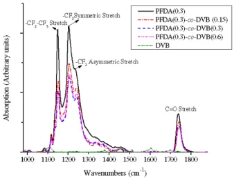
deposited on blank Si wafers using iCVD technique with t-butyl peroxide (TBPO) as the initiator. Different flow rates of DVB (0.15 sccm, 0.3 sccm and 0.6 sccm) are used for a given flow rate of PFDA (0.3 sccm) to study the addition of DVB on the polymer composition. Given the same thin film thickness in the samples, FTIR spectrum (Fig. 1) reveals significant reduction in C-F (1149, 1203, 1232 cm−1) and C = O (1738 cm−1) [12] bond density in the co-polymer (p(PFDA-co-DVB)) compared to the homo-co-polymer (pPFDA) as a consequence of the incorporation of DVB.
The thermal degradation of the acrylate family is mainly due to C = O bond dissociation and occurs around 250°C – 300°C [10, 16, 17]. However, our previous work [10] has shown that at low temperatures, high density plasma chemical vapor deposition of dielectrics can be carried out to hermetically seal such a polymer and make it compatible for multi-layer stacking. Also, Ma et. al [1] have discussed the processability and various patterning techniques of halogenated acrylates in detail thereby encouraging the adoption of this class of polymers for our study. Recently, iCVD based patterning technique of pPFDA on curved substrates has also been explored [18]. It is important to note that the patterning associated edge roughness doesn’t affect the loss performance of the device as the polymer is used as an over-cladding where its edge does not interact with the optical mode.
#172210 - $15.00 USD Received 10 Jul 2012; revised 13 Aug 2012; accepted 16 Aug 2012; published 27 Aug 2012
Fig. 1. Characteristic FTIR bands of pPFDA correspond to –CF2-CF3 end group at 1149 cm−1, symmetric stretching of -CF2 moiety at 1203 cm−1, asymmetric stretching of –CF2 moiety at 1232 cm−1, and C = O stretching at 1738 cm−1. Addition of DVB as a cross- linker brings down the intensity of these characteristic bands in the copolymer.
4. Refractive index and TO performance
The addition of DVB affects the optical properties of the polymer in two ways. Firstly, the addition of an aromatic group improves the packing density thereby increasing the refractive index. Secondly, the decrease in C-F bond density has an associated increase in “x” (Eq. (2)) and a corresponding increase in n. This is supported by the index measurements at 633 nm where n(pPFDA): 1.33, n(pDVB): 1.57 and n(p(PFDA-co-DVB)): 1.38.
The TO coefficients of the polymer can be measured by using them as a top cladding for an amorphous Si (a-Si) racetrack resonator. The transmission spectrum of the resonator at various temperatures reveals the resonance peak shift with temperature which can be related to the effective TO coefficient of the device (Eq. (5)). The TO coefficient of the polymer can be deduced from the effective TO coefficient of the device as the TO coefficients of a-Si (2.3 × 10⁻⁴) and SiO2 under-cladding (1 × 10⁻⁵) are known.
1 eff 1 r g r dn d n dT dT λ λ = (5)
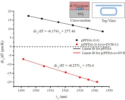
The TM transmission resonances corresponding to racetrack resonators (coupling length: 100 µm, coupling gap: 600 nm, ring radius: 20 µm) with a-Si core (550 nm x 205 nm), 3 µm SiO2 under-cladding and 2 µm iCVD polymers (Fig. 2 inset) are measured between
25°C-70°C. The TO peak shift for PFDA (flow rate: 0.6 sccm) cladded devices is positive compared to that of the co-polymer (PFDA flow rate: 0.6 sccm, DVB flow rate: 1 sccm) cladded rings suggesting a significant increase in the magnitude of the TO coefficient due to DVB addition (Fig. 2). FIMMWAVE simulations suggest that PFDA has a TO coefficient of −2.1 × 10⁻⁴ while the co-polymer has a TO coefficient of −3.1 × 10⁻⁴. The increase of the TO coefficient by 1.48x due to the addition of DVB can be understood from Eq. (4). The index increases by 1.04x on DVB addition which translates to a 1.17x increase in the index dependence factor of the TO coefficient in Eq. (4). The remaining increase in TO coefficient can be attributed to the increased αV of the co-polymer due to the addition of DVB with
higher αV (8.6 × 10⁻⁴ [19]) to an acrylate with lower αV (0.5 - 0.9 × 10⁻⁴ [20]). It can also be
understood by the reduction of strong C-F bonds in the co-polymer increasing its αV.
#172210 - $15.00 USD Received 10 Jul 2012; revised 13 Aug 2012; accepted 16 Aug 2012; published 27 Aug 2012
Fig. 2. The resonance peak shift with temperature is positive for the pPFDA top cladding while negative for the p(PFDA-co-DVB) top cladding suggesting that the TO magnitude of copolymer (−3.1 × 10⁻⁴) is higher than that of pPFDA (−2.1 × 10⁻⁴). The inset shows the schematic of a-Si resonator whose TM transmission is measured at various temperatures for 2 different iCVD polymer top cladding choices: pPFDA (flow rate: 0.6 sccm) and p(PFDA-co-DVB) (flow rate: 0.6 sccm) (flow rate: 1 sccm).
5. Design implications
For a given core choice, a polymer top cladding with higher index and higher TO magnitude is desired for athermal applications. This is because a higher index would lower the index contrast thereby ensuring greater mode expansion into the cladding. Similarly, a higher TO magnitude of the cladding would mean passive thermal compensation for a larger core dimension. For instance, assuming an a-Si core (n: 3.48, TO: 2.3 × 10⁻⁴) and SiO2
under-cladding (n: 1.46, TO: 1 × 10⁻⁵), the bending loss performance of pPFDA (n: 1.33, TO: −2.1 × 10⁻⁴) and p(PFDA-co-DVB) (n: 1.38, TO: −3.1 × 10⁻⁴) cladded devices can be compared for athermal design for a TM mode choice. The pPFDA has a lower TO coefficient than p(PFDA-co-DVB). Hence, thermal compensation of a-Si core occurs at a much lower confinement factor for the homo-polymer cladding compared to the co-polymer cladding. FIMMWAVE simulations indicate that pPFDA cladded devices have an neff of 1.6 for athermal core
dimension of 550 nm × 190 nm, while p(PFDA-co-DVB) cladded devices have an neff of 1.78
for a core dimension of 550 nm × 212 nm. Higher neff of p(PFDA-co-DVB) cladded device at
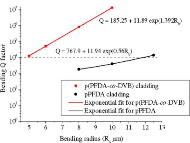
athermal condition results in a tighter confinement for a given bending radius resulting in a higher bending Q (Fig. 3). Hence, for a bending Q of 104 (minimum desired bending Q for a good filter performance), FIMMWAVE simulations indicate that co-polymer cladded device has a bending radius of 5 µm (Fig. 3) and an FSR of 20 nm which is twice the FSR of the PFDA cladded device (10 nm for bending radius of 12.5 µm). In a Si WDM architecture with a given channel spacing, a 100% improvement in FSR and footprint (Fig. 3) performance results in twice the number of channels thereby doubling the bandwidth capacity.
#172210 - $15.00 USD Received 10 Jul 2012; revised 13 Aug 2012; accepted 16 Aug 2012; published 27 Aug 2012
Fig. 3. Bending loss performance of both the cladding choices are compared by plotting the simulated bending Q for various bending radii. For a bending Q of 104, co-polymer cladded device has a bending radius of 5 µm while that of PFDA cladded device is 12.5 µm
6. Summary and conclusions
This work utilizes iCVD to compare the optical properties of pPFDA and its co-polymer with DVB (p(PFDA-co-DVB)). According to our experiments, C-F bond density seems to be the crucial controlling parameter for the n and TO properties of the fluorinated acrylates. Co-polymerization of PFDA with DVB decreases the C-F bond density that increases the packing density thereby increasing n. The increased TO coefficient of the co-polymer arises due to increased n and αV accompanying the DVB addition. This opens up possibilities of tailoring
the TO coefficient of PFDA by controlling the degree of cross-linking with DVB. A significant improvement in footprint and FSR performance of an athermal device, for a given core choice, can be achieved by tailoring the properties of the polymer top cladding.
Acknowledgment
We would like to thank Harvard CNS, MIT-MTL and MIT-CMSE for their support in fabrication and measurement. This work was partly funded by the U.S. Government under the DARPA UHPC program. The views and conclusions contained herein are those of the authors and should not be interpreted as representing the official policies, either expressed or implied, of the U.S. Government. This work was partly supported by the Fully LASER Integrated Photonics (FLIP) program under APIC Corporation, supervised by Dr. Raj Dutt, and sponsored by the Naval Air Warfare Center-Aircraft Division (NAWC-AD) under OTA N00421-03-9-002. The authors also acknowledge the financial support of the MIT Institute for Soldier Nanotechnologies (ISN) under Contract DAAD-19-02D-0002 with the U.S. Army Research Office.
#172210 - $15.00 USD Received 10 Jul 2012; revised 13 Aug 2012; accepted 16 Aug 2012; published 27 Aug 2012