PFC/JA-90-41
CIT Elongation Tradeoffs Studies*
L. Bromberg
J. Wei
October 1990
Plasma Fusion Center
Massachusetts Institute of Technology
Cambridge, Massachusetts 02139
Ninth Topical Meeting on the Technology of Fusion Energy, Sponsored by
The American Nuclear Society and the U. S. Department of Energy, Hyatt
Regency Oak Brook, Oak Brook, Illinois, October 7-11, 1990.
*This work was supported by the Princeton Plasma Physics Laboratory
Subcontract S-02969-A.
L. Bromberg and J. Wei
MIT Plasma Fusion Center, Cambridge, MA 02139
Abstract
Results from a study on the effects of increasing
the vertical height of the vacuum chamber of CIT are presented in this paper. The increased vertical height
would allow for either larger plasma elongation or
in-creased distance between the x-point and the vacuum
vessel.
I. Introduction
The implications on the toroidal and poloidal field systems of increasing the vertical height of the vacuum chamber of CIT is studied. An increased vertical height of the vacuum vessel would allow for either larger plasma elongation or increased distance between the x-point and the vacuum vessel. Increased elongation would increase
q at constant plasma current, while increasing the
dis-tance between the plasma and the target may facilitate placing a closed divertor.
Few changes were incorporated on the baseline PF system. The height of the poloidal field coils on top of the machine has been increased in order to accomodate the increased vertical height of the toroidal field coils and vacuum vessel, but have not altered the other coils.
A goal is to determine whether a set of coils optimized
for one set of parameters (elongation) could be used for different plasma elongations and/or vacuum vessel
height.
Static equilibria for start-up, beginning of flat top (BOFT) and end of flat top (EOFT) have been calcu-lated for several cases, including for the baseline plasma (elongation = 2 at the 95% surface) but with designs with half-height increments of 0.2 m, 0.4 m and 0.6 m. Results of increased plasma elongation, up to 2.4 are also presented.
The organization of this paper is as follows: in sec-tion II the plasma stationary equilibria for start-up, be-ginning of flat top (BOFT) and end of flat top (EOF) are described. This has been done for the baseline plasma (elongation = 2 at the 95% surface) but with designs with half-height increments A, of 0.2 m, 0.4 m and 0.6
In.
t Supported by Princeton Plasma Physics Lab.
Subcontract S-02969-A.
In section III, results are presented for a case in which the vacuum vessel half-height has been increased by A, = 0.2 m, and with an x-point 0.05 m from the divertor target (x-point height increased by a. = 0.3 m higher than in the baseline case).
In.section IV, the poloidal field system power and
energy for the various equilibria are compared. In
sec-tion V, the out-of-plane loads and the corresponding out-of-plane shears of the toroidal field coil are calcu-lated. In section VI the implications of increased elon-gation and/or height of the vacuum vessel on the plasma vertical stability is considered. Finally, the conclusions are presented in section VII.
II. Baseline plasma equilibria for increased height
of TF coil.
Figure 1 shows the plasma and poloidal field coil
location of the baseline configuration (from the CIT System Design Document, SDD)1
. The details of the
poloidal field system have been obtained from a case2 of
the wedged magnet. The major and minor radii are 2.1
and 0.646 m, the toroidal field is 10 T and the plasma current is 11 MA.
In this section the sensitivity of the equilibria con-figuration to the location of PF4 and PF5 is analyzed (see Figure 1 for the identification of the poloidal field coils). The height of PF4 and PF5 has been increased by 0.2 m, 0.4 m and 0.6 m (corresponding to increments in total machine heights of 0.4, 0.8 and 1.2 m respectively). The plasma poloidal flux contours for the different cases are superimposed in Figures 2 through 4. The plasma parameters are held constant while the height of PF4 and PF5 is increased. Startups for the four cases (baseline height, 0.2, 0.4 and 0.6 m increased PF coil location) are shown in Figure 2. Figure 3 shows the results for BOFT (beginning of flat top). Figure 4 shows the results for EOFT (end of at top).
In Figures 2-4, the size of the coils is directly pro-portional to the amount of current flowing through the coil. They do not correspond to the physical size of the coils. The direction of the current can be determined in Figures 2-4 by the presence or absence of crosses in the coils.
2
PF4 PF5 PF3 PF6 PF2EPF7
PF1\
Ii
F1. Elvaio vewofCI dsin
Fig 1. Elevation view of CIT design. Document drawing 500 I 0 500
0
a.. as. * *6 166 UUU S.. a a a -UI
500Fig 3. Equilibria for 0408 BOFT. Ah= 0., 0.2 m, 0.4 m and 0.6 500 System Design 0 I
-7
666 a.. 666 a.. S.. 500Fig 4. Equilibria for 0408 EOFT. Ah= 0., 0.2 m, 0.4 m and 0.6
Increasing the plasma-PF4 coil separation has
lit-tle effect on the currents in PF4 and PF5. This surpris-ing result indicates that most of the plasma shapsurpris-ing is done by PF1-PF3. The current in PF1 has been kept constant, since PF1 is already at the temperature and heating limits. The only change from increasing the height has been a small reduction of the volt-seconds at startup for At = 0.2 m, made up by increasing the flux swing between the beginning and end of flat top. For the case of A, = 0.4 m, the PF system actually delivers slightly more inductive flux than the baseline PF. 500
Fig 2. Equilibria for 0408 startup. A,= 0., 0.2 m, 0.4 m and 0.6
0
6U e.g 666 606 666 6Q6 666 e.g 606 I.. S.. a.. S.. 66U 066 066 6663
a
III. Increased plasma elongation equilibria with increased vacuum vessel height
In this section, results from increasing the plasma elongation while keeping the constant plasma current (i.e., increasing the value of q) are presented. The plasma inductance is lower than in the baseline case due to the increased elongation. Therefore, required flux linkage was decreased by 2 Volt seconds.
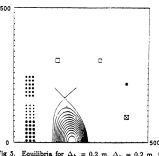
Figure 5 shows typical results for the case in which the height of the x-point is increased by A, = 0.20 m. The height location of the poloidal field coils has also been increased by 0.20 m toaccommodateAh = 0.2 m. Therefore, the x-point to divertor target geometry is similar to that of the baseline. To study the effect of sweeping the x-point on the poloidal field system, the plasma triangularity has been varied. The radial loca-tions of the x-point are 1.73 m in Figure 5(a) and 1.90
m in Figure 5(b), corresponding to a radial sweep of the x-point of 6r.,, = 0.17 m. In order to decrease the
radial location of the x-point (increase the triangularity) the current in PF4 is increased and the current in PF5 is decreased. Large changes in the location of the x-point are possible with small modifications of the currents in these two coils.
500 [ . 0 - '500 500 0 U U6O SU* us. leg 06s /
a
Fig 5. Equilibria for At = 0.2 m, A, = 0.2 m, for different radial position of the X-point: a) 1.73, b)
1.90 M.
If the plasma elongation is increased to A. = 0.3
m, a suitable divertor with Ah = 0.2 m has been difficult
to obtain without modifying the poloidal field system. The baseline PF coil system produces plasma equilib-ria with substantial amount of indentation. With in-creased elongation, the pulling from PF2 increases and bean shaped plasmas are formed.
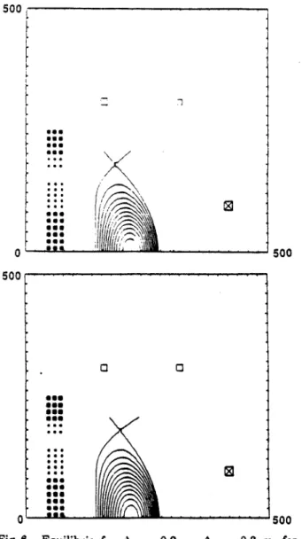
To produce a more CIT-like divertor, the PF3 coil was split into two sets of coils. PF3 is the most easily accessible coil of the OH stack. Figure 6 shows the re-sults for the case with split PF3. The radial location of the x-point is 1.85 m for Figure 6(a) and 1.95 m for Figure 6(b), corresponding to , = 0.10 m.. The
x-point in this cases is about 0.05 m from the divertor
target.
The current in the upper part of PF3 has increased.
Again, to sweep the x-point the current shifts from PF5 to PF6 (the coils are renamed because of the introduc-tion of a new coil).
The location of the PF coils for the baseline have been determined from an optimization for a plasma elon-gation of 2 at the 95% flux surface. Although appropri-ate for operation for xos = 2.2, it is not appropriate for larger elongations. If larger elongations are desired (x-point very near the baseline divertor target) addi-tional flexibility should be provided for the PF system. The chosen modification (splitting PF3 into two sepa-rate coils) may not be the optimal. It has been the intent of this work to show that it can be done with relative ease, without fully optimizing the design.
4
IV. Calculations of power/energy.
In this section the power and energy of the cases discussed above are presented.
The calculations are referred to the 0408 case2. It
is assumed that the inconel is at the same temperature
as the copper. Table 1 shows the results for the baseline
case and the cases with Ah, = 0.2 and 0.4 m, using the equilibria described in section II. There is very little effect on both the energy and the power of increased vacuum vessel elongation, a consequence of the fact that
central stack (PF1, PF2 and PF3) is mainly responsible
for the shaping.
500 0 500 S.. S.. S.. .3. 606 U.. U.. U.. U..
0
(f~~2~
0 iFig 6. Equilibria for A,, = 0.2 m, A. = 0.3
m
different radial position of the X-point. a) 1.81.95 m.
Table 1 also summarizes the results for the cases
with A. = 0.2 and 0.3 m. The case with A, = 0.2 m corresponds to the equilibria shown in Figures 5(a) and 5(b) for the flat top (br,,,.,, = 0.17 m) and the
equilibria for A. = 0.3 m (corresponding to a 0.05 m
gap between the x-point and the divertor target) are
shown in Figures 6(a) and 6(b) (6r,,,. = 0.1 m). The
power for the A. = 0.2 is about the same as in the case of smaller plasma elongation shown in Table 1, but the energy has increased by a moderate 200-300 MJ.
The reason for the large increase in energy and power between the cases with A. = 0.2 rn and A = 0.3 m is because of the decrease in current in PF6 (Figure 5)
as 6 is increased. The current in the main equilibrium coil (PF7 in Figure 5) increases. The larger temperature excursion of this coil is reponsible for the substantial increase in power and energy. It should be possible to bring the situation close to that of the smaller elongation
by shifting the equilibrium currents between these two
coils and reoptimizing the coils. V. Out-6f-plane considerations
In this section, the TF out-of-plane loads for the several cases discussed above are compared.
A simple code has been used to calculate the shear
produced in the wedged toroidal field coil by the PF-TF interactions. The model used is based on the orthotropic
toroidal thick-shell model, treating the magnet assembly as a thick, continuous orthotropic shell. The thickness
Soo of the magnet and the elastic moduli (allowed to be different in two directions) are allowed to vary along the length of the magnet. The treatment is axisymmetric, but by appropriately changing the moduli along the shell it is possible to study the global effects of ports. Stress concentrations would require a full 3-d analysis, beyond the scope of this work.
The results from this code are approximate, and only the global results are presented. In particular,
the effects of field variation across the thickness of the magnet are not included. The global behavior and the trends, however, are reasonably well represented with this code.
The shear stresses are calculated for the start-up, BOFT, EOFT and current-conserving disruption (plasma current disappears while the PF coil currents remain constant) at the BOFT. Table 2 summarizes the results. rt., is the distance along the coil where the coil turns
lose contact with the adjacent turns. T
... and 1,,,, are 500 the maximum and the minimu shear stresses, while rm. and rmin are the locations along the coil where
, for maximum and minimum are located, respectively. 5, b) C 060 a.. U.. 660 U.. mOO U.. *63 em. L.
""
0Table I
PF System Characteristics Baseline
Increased half height Ah (M) 0 0.2
Increased x-point height A. (m) 0 0
Maximum Energy (Stored and Dissipated)
Time of Max. Energy (s) 26.26 26.26
Stored Energy (MJ) 270 315
Dissipated Energy (MJ) 3150 3275
Total Energy (MJ) 3400 3590 Max. Store Energy(MJ)
-Max. Dissipated Energy(MJ) Peak Power
Time of Peak Power (s)
Magnetic Power (MW) Resistive Power (MW) Peak Power (MW) Flux Swing Start-Up Flux (V-s) EOFT Flux (V-s) 930 975 990 1110 1130 3210 3370 3440 3550 4890 13.76 265 177 440 6.0 325 125 450 6.0 330 125 456 13.76 280 180 460 13.76 365 295 660 23.2 23.0 23.7 23 23 -30.3 -30.6 -30.4 -28.6 -28.3 Table 2
Toroidal Field Coil Shear Stresses apered 7(M)2 (in) (MPa) A. = 0, A, = 0 start-up BOFT EOFT BOFT-disruption A. = 0, A, = 0.2 start-up BOFT EOFT BOFT-disruption 2.1 2.1 2.1* 2.1 2.3 2.3 2.3 2.3 a. = 0.2, a& = 0.2 start-up 2.3 BOFT 2.3 EOFT 2.3 BOFT-disruption 2.3 A, = 0.3, A, = 0.2 start-up 2.3 BOFT 2.3 EOFT 2.3 BOFT-disruption 2.3 12 30 38 48 15 42 42 65 13 35 30 53 15 30 32 53 (m) (MPa) (m) 1.4 0.4 0.3 0 1.4 0.4 0.3 0 1.5 0.4 0.4 0 1.5 0.4 0.3 0 -18 -45 -35 -65 -34 -40 -35 -57 -18 -30 -30 -40 -18 -20 -23 -38 2.5 2.0 1.9 2.0 2.6 2.0 2.1 2.1 2.7 2.6 2.6 2.5 2.7 2.7 2.7 2.4
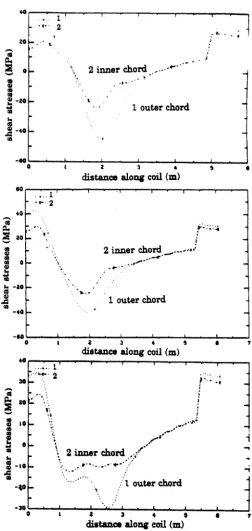
Figure 7 shows, for the inner and outer chords of the magnet, the shear stresses as a function of the dis-tance along the magnet starting at the inboard mid-plane, calculated at BOFT current conserving disrup-tions. The baseline case (Fig. 7(a)), and the cases with
Ap, = 0.2 m with A. = 0 (Fig. 7(b)) and A. = 0.2 m
(Fig. 7(c)) are shown.
The shear stresses in the upper inner leg are slightly larger in the case of elongated vacuum vessel with a baseline plasma. However, the shears are reduced to comparable levels in the case of A, = A. = 0.2 m.
There are substantial stresses in regions where there is little support by wedging. Therefore the ability of car-rying out-of-plane loads by wedging in that area is still a reason for concern, and does not change appreciably as the vacuum vessel height is increased.
VI. Vertical stability considerations
Highly elongated plasmas are susceptible to a
ver-tical instability. Passive conductors and the vacuum ves-sel slow down the growth of the mode. Passive stabi-lizers do not completely stabilize these modes since the stabilizing currents decay. The resistive diffusion time is 7D
= " , where b is a measure of the minor radius
of the vacuum chamber and d is the thickness. For CIT,
b ~ 0.66 m, d - 0.067 m, and 77 - 1.3 x10- fl m, 7D ~
4.3 x 10⁻² sec. This value is in approximate agreement with more detailed calculations, with rD ~ 5.6 x 10⁻²
s, performed by Kessel and Jardin4. 0.2 0.2 0.2 0.3 0.4 0 26.26 387 3340 3730 26.26 380 3450 3850 26.26 315 4800 5100
6
The vertical stability of the plasma has been ana-lyzed using a simplified model5. The plasma boundary is chosen at the 95% flux surface and the plasma equilib-rium is determined by the variational method. Figure 8 shows the plasma surface and the filamentary model of the vacuum vessel. Since the most unstable modes tend to be mainly vertical and incompressible, the plasma displacement is written in the form,
4(r, t) = (R)e"ez, with
where is the displacement (assumed to be in the verti-cal direction), -y is the growth rate, R is the distance from the major axis and ez is in the vertical direc-tion. This assumption, which considerably simplifies the analysis, allows for an R dependence of the vertical dis-placement eigenmodes ,(R). This model is an improve-ment with respect to the rigid displaceimprove-ment model. The model uses the extended energy principle to estimate the resulting growth rate for a system without a perfectly conducting wall.
Four cases have been studied. The results are shown in Table 3. The growth rate for the case of both elongated plasma and increased vacuum vessel height is almost three times larger than that of the baseline de-sign, making the vertical plasma control more demand-ing.
Section VI1. Conclusion
It has been shown that increasing the height of the vacuum vessel has little effect on the characteris-tics of the poloidal field system for the baseline plasma. The implication is that the coils in the throat of the magnet are mainly responsible for the shaping. If elon-gation greater than P.9 = 2.2 are desired, the poloidal field system should be reoptimized. The out-of-plane behaviour of the toroidal field coil has been found not to be sensitive to increased elongation of the vacuum chamber. The vertical stability of the plasma has been analyzed, and not surprisingly, it has been determined that the growth rate of the vertical stability increases by about a factor of three if the elongation and the vacuum vessel height are increased.
References
[1] CIT Design Team, "System Design Document,
Com-pact Ignition Tokamak", Report
W-881201-PPL-05, December 1 (1988)
[21 R.D. Pillsbury, Jr, "PF System for the CIT 2.1 m Machine", Memorandum MIT-PF040888, April 8
(1988)
(3] E.S. Bobrov, "Structural Response of Tokamak TF
Magnet Systems to In-Plane and Out-of-Plane Elec-tromechanical Loads", Nucl. Engineering and
Design-/Fluion, Vol 1, p 39-50 (1984)
[4] C. Kessel and S. Jardin, CIT Report
AE890609-PPL-01 (1989)
(5] Haney, S.W., and Fteidberg, J.P., "Variational
Meth-ods for Studying Tokamak Stability in the Pres-ence of a Resistive Wall, Phys. Fluids, Vol. 1,
1637 (1989) a -as -4 - 2 -2 inner chord
---1
1 outer chord 0 & 2 5distance along coil (m)
do, 40 4a0 a8 40 a a 0 I.. 44 a I.. a a A S 0 1 a 3 4
distance along coil (m)
5 7 40 to-a 2 inner chord.,: --I -. . 1. outer chord -3
distance along coil (m)
a 7
Fig 7. Shear stresses in the inner and outer fibers for a current conserving disruption during BOFT: a) base-line; b) A, = 0.2 m, A. = 0; c) A, = 0.2 m, A, =0.2 - - 2 2 inner chord. -1 - t -1 outer chord
Table 3
Growth Rate of the
Vertical Stability Ah (A (z (m) (m) (Hz)
o
0 0.2 0 0 0.2 0.2 0.2 99 140 160 270 20 I *-- . I 1.0 15 20 2.5 3.0 3.5 R (m)Fig 8. Plasma and vacuum vessel model for the calcu-lations of the vertical instability
20 'f '2 08 0.4 00 -04 -08 -12 -f6 - a a * 0 a a a a o a * a N