Publisher’s version / Version de l'éditeur:
Vous avez des questions? Nous pouvons vous aider. Pour communiquer directement avec un auteur, consultez la première page de la revue dans laquelle son article a été publié afin de trouver ses coordonnées. Si vous n’arrivez pas à les repérer, communiquez avec nous à [email protected].
Questions? Contact the NRC Publications Archive team at
[email protected]. If you wish to email the authors directly, please see the first page of the publication for their contact information.
https://publications-cnrc.canada.ca/fra/droits
L’accès à ce site Web et l’utilisation de son contenu sont assujettis aux conditions présentées dans le site LISEZ CES CONDITIONS ATTENTIVEMENT AVANT D’UTILISER CE SITE WEB.
Internal Report (National Research Council of Canada. Division of Building Research), 1975-09-01
READ THESE TERMS AND CONDITIONS CAREFULLY BEFORE USING THIS WEBSITE.
https://nrc-publications.canada.ca/eng/copyright
NRC Publications Archive Record / Notice des Archives des publications du CNRC : https://nrc-publications.canada.ca/eng/view/object/?id=27b807ce-fd73-4e7a-943c-b3ae55873360 https://publications-cnrc.canada.ca/fra/voir/objet/?id=27b807ce-fd73-4e7a-943c-b3ae55873360
Archives des publications du CNRC
For the publisher’s version, please access the DOI link below./ Pour consulter la version de l’éditeur, utilisez le lien DOI ci-dessous.
https://doi.org/10.4224/20359030
Access and use of this website and the material on it are subject to the Terms and Conditions set forth at
Fire testing of rigid cellular plastics
DIVISION OF BUILDING RESEARCH
FIRE TESTING OF RIGID CELLULAR PLASTICS by
A. Rose
Internal Report No. 422 of the
Division of Building Research
OTTAWA September 1975
Small-scale flammability tests for certain low-density rigid cellular plastic foams have been criticized as highly misleading as indicators of the real fire behaviour of these materials.
This is also true in part of the 25-foot tunnel test (ASTM E84-70) for foams which give flame-spread classifications above 40 by this test.
This report describes the NRC/DBR corner wall test.
It compares the results of this ad hoc test, using four ignition sources, with tunnel furnace ratings and oxygen index values for a variety of foams.
The complexity of the problem of assessing the real fire hazard of these foams is emphasized, and an explanation is
suggested for the marked differences between their behaviour and that of the usual cellulosic building materials.
Ottawa
September 1975
C.B. Crawford Director, DBR/NRC
by A. Rose
The ASTM E84-70 25-ft tunnel testl (also issued as NFPA 255,
UL 723, ULC Sl02) is the principal North American method used for the determination of flame spread classification (FSC), fuel contributed* (FC) and smoke developed (SO) of building materials, particularly for regulatory purposes. Using a scale based on high-density asbestos-cement board as zero and select l3/l6-in. tongue-and-groove red oak flooring as 100 for each of the three attributes mentioned above (collectively termed the "fire hazard classification"), it has been generally accepted as reasonably indicative of the comparative ウオイヲ。」・セ「オイョゥョァ characteristics of conventional building materials in typical fire situations.
With the proliferation of synthetic polymeric products used in construction, particularly rigid foamed plastics, the tunnel test has been increasingly criticized as inadequate and misleading. This has been particularly true in the case of low-density foamed plastic products some of which melt and drip (e.g., polystyrene) and others (e.g., polyurethane and polyisocyanurate), which react to fire in a manner and at a rate quite different from cellulosic materials of nominally similar FSC's. It is not surprising that these differences in mode of decomposition and thermal properties should lead to anomalous behaviour and difficulties in interpretation of E84 results in terms of real or potential hazard. Nor is it
surprising, in the light of the size and cost of the tunnel test, that small-scale tests have been used, despite disclaimers in the wording of the tests, to indicate the relative performance of some foamed plastics in fire. An example of such a test is
ASTM D1692-74,2 a small-scale horizontal test for rigid or flexible foamed plastics. Until recently, the results of D1692 tests have been unofficially quoted, in both research'and
advertising literature, as indicating "self-extinguishing" or "slow burning" properties, depending on the distance and duration of flame spread. Work at OBR/NRC has shown that polyurethane foams with FSC's of 300 to 500 (E84) can be rated as "self-extinguishing" by the 01692 method.3
*
ASTM E84 states that "there is not necessarily a relationship among these measurements." In most cases little importance is attached to FC, but some building officials and research personnel consider it worth recording.Other small-scale tests that have been used extensively in development work are ASTM D635-744 and ASTM D30l4-74,5 the latter based on the Butler Chimney Test. The Oxygen Index Method
(ASTM D2863-74)6 has been increasingly favoured as a measure of the intrinsic flammability of plastics.
Small-scale flammability tests have never been invoked in the National Building Code of Canada; the 1975 version of the Code calls for E84 FSC's of 25 or 100 in specific insulation and
acoustical applications in noncombustible constructions. A literal interpretation of other clauses in the 1970 and 1975 editions of the NBC would suggest that an FSC up to 150 is permissible for foamed plastics used as interior finish in certain combustible constructions and specific occupancies.
Corner Wall and Related Tests
In the light of its work and information from many other sources, DBR/NRC considered it advisable to proceed in 1973 with the development of a simulated fire test and with modification of tunnel furnace procedures to give better agreement with the known fire behaviour of certain foams and the results of reasonably realistic fire tests.
Several research organizations have used ad hoc tests,
including various modifications of the so-called "corner wall test," in an effort to assess the real hazards of low-density rigid foams. Factory Mutual Research Corporation (FMRC) has carried out an
extensive series of tests7 for the Society of the Plastics
Industry (SPI) and individual sponsors. These tests involved walls 40 and 50 ft long and 25 ft high with a full ceiling. The fuel source was 750 lb of wooden pallets. The materials tested included polystyrene beadboard, polyurethane, polyisocyanurate and phenol-formaldehyde foams. Some were tested in the exposed condition as well as with sprayed fire-retardant coatings, such as magnesium oxychloride and treated cellulosic compositions. The effectiveness of sprinklers in various configurations in limiting damage to the structures was a major objective of the study.
The medium-scale corner wall test now to be described
originated at the U.S. Forest Products Laboratory (USFPL), Madison, Wisconsin, in 1952.8 It was intended to evaluate the effectiveness of fire-retardant paints on conventional lining materials. In this test, two 2- by 8-ft panels were fastened to the corner of an
8- by 8- by l2-ft room of concrete block construction. The ceiling lining was a 4-ft-wide "L" over the corner. A I-in. gap was left between the test panels and the structure on all surfaces. Air supply was through a 20- by 8-in. opening at floor level diagonally opposite the test corner. Two 4- by 8-in. flues in the roof, 6 ft
along the edge of the specimen from the test corner, were used as indicators of the endpoint if flames issued from them in the course of the test, i.e., in the event of a substantial flashover. The fuel used was a 5-layer crib of 20 hard maple sticks, 7/8- by 7/8- by l2-in. weighing 2.25 kg at 7 per cent moisture content .-nd ignited by 50 ml of alcohol. This source reached peak intensity in 5 to 6 min. and burned for 12 to 13 min. from the time of ignition of the alcohol.
In spite of the inevitable variability in the rate of
development of the crib fire and involvement of the walls, USFPL claimed satisfactory correlation between the corner wall test anu their 8-ft tunnel furnace (ASTM E286-69),9 but the test was
apparently never seriously considered as a potential basis for a standard method.
The 8- by 8-ft corner wall arrangement at DBR/NRC was built in 1969 to test lining materials and coatings previously evaluated by the ASTM E84 and ASTM E16210 methods. The original walls were constructed of 3/8-in. low-density asbestos-cement board
(45 lb/cu ft) over nominal 2 by 4 studding with a roof of 1/4-in. board of the same type. Any exposed studding was protected by a layer of No. 10 asbestos paper. The original open corner
arrangement was later modified by the addition of a 2-ft-deep skirt to confine the combustion gases and enhance flashover effects within the truncated ceiling area (Fig. 1). Two 4- by 8-in. vents were located 6 ft from the test corner along the ceiling joint as in the USFPL arrangement.
In the original DBR/NRC arrangement, 12 thermocouples
recorded temperatures on the walls, at the corner at the ceiling and at the inner angle of the 4-ft "L". When the structure was reactivated and reinforced in 1973, only eight thermocouple locations were incorporated, including one above the ignition source and one 6 in. below the ceiling and 2.5 in. out from the wall surfaces (Fig. 2).
Test specimens were usually fastened to the walls and ceiling by nailing into the studding and roof supports through l-in.-diameter washers to minimize pull-through if the panels buckled or bulged during the test.
Selection of Materials
Before the initiation of the present corner wall program, the Fire Section had carried out a number of E84 tests on polystyrene, polyurethane, polyisocyanurate, urea-formaldehyde and
phenol-formaldehyde foams for both research and industrial purposes. The rapid deposition of smoke on the observation windows in the case
of the first three types, makes determination of the FSC in the 20 to 75 range more difficult than for conventional cellulosic lining materials in this same range. To compound the difficulties, some polyurethane and polyisocyanurate foams sag, intumesce, or exfoliate sufficiently to deflect the flame front, change the air flow in the tunnel, and render the results conjectural in some cases. This was particularly true of materials 12 and 17
(Table I). Chicken wire (2-in. hexagonal mesh) wrapped around the specimen and laced on the back minimizes these effects but may reduce slightly the nominal FSC in the range 25 to 60. It is in this range that differences in performance of rigid urethane foams in the corner wall test are accentuated and the shortcomings of the tunnel test in assessing real fire hazard are more obvious. For example, in the case of material 12-1, the FSC was reduced from a conjectural 55 to a more definite 40 by the use of chicken wire. Another advantage of using chicken wire, even if wrapped around only the last 3 or 4 ft of the specimen (vent-end of tunnel) is that, supplemented by the addition of a pair of
1.5-in.-wide metal strips about 9 in. upstream and downstream of the vent-end thermocouple, it minimizes potential fouling of the thermocouple by the specimen. It thus assures more accurate recording of vent-end temperatures and hence confirmation of visual determination of the position of the flame front near the end of the tunnel. (In many cases, vent-end temperatures are also significantly reduced by deposition of a persistent soot coating in the early minutes of the 10-min. test.)
When the corner wall program was being planned, there were very few board or sprayed foams of the urethane/isocyanurate family, domestic or imported, in the critical (20 to 75 FSC) range, readily obtainable in adequate quantities. This was due in part to the general shortage of petroleum-based intermediates at the time and in part to the difficulty encountered by suppliers in hiring skilled operators to apply sprayed foams in a manner that would ensure uniform composition, density and flammability over the whole area of the specimens. This was true even when the supplier was attempting to cooperate fully in the program. Only in the case of some board foams (laminates with aluminum foil
faces) submitted for commercial tests was sufficient extra material usually available for replicate runs in the early stages of the work. In such cases, by using certain expedients to minimize smoke deposition on the windows, repeatability was satisfactory for isocyanurate foams of 20 to 30 FSC. Later, imported
boardstocks (materials 11, 12 and 13 in Table III-C) became available in adequate quantities.
The polystyrene beadboards selected were representative of the low-density types commonly used, often without protective coverings, in residential and commercial construction.
The 23 materials tested to date are listed, with their relevant physical properties and oxygen index values (where available), in Tables IA to IE. In addition, the effectiveness of a UL-listed fire-retardant intumescent latex paint (T) on
materials 2 and 12, as well as a more highly intumescent experimen-tal water-based paint (F) on materials 10, 12 and 18, was
investigated.
The materials were grouped as follows:
I Conventional finish materials: Fibreboards, plywoods, etc.
II Polyurethane/polyisocyanurate laminates: Boards
produced on a continuous foam machine with aluminum foil (one mil) or foil/kraft paper faces with core densities (foil removed) of 2.0 to 3.0 Ib/cu ft. III Polyurethane/polyisocyanurate boardstock: Foams of
1.8 to 2.2 Ib/cu ft density, 1 in. thick, sawn from large blocks or slabs.
IV Polyurethane/polyisocyanurate sprayed foams: Applied at nominal I-in. thickness to 3/8- or 1/2-in. plywood by mixing gun; intrinsic "skin" left intact except in the case of material 18, where the irregular surface was planed to give 1.0-in. net foam thickness.
V Phenol-formaldehyde foams: One sample of 1.0-in. boardstock.
VI Polystyrene thick in grades. validity
In the case of the raw and factory-finished fibreboards and several of the urethane and isocyanurate foams, two or more lots were acquired over the period of this work, with inevitable
differences in performance. Different lots are identified by the suffix: -1, -2, -3, etc.
In the case of the foam laminates, those tested with the foil or foil/kraft facing intact are identified by the suffix "F"; those with the test face stripped by "X". Because later work revealed that the top and bottom faces (as oriented on the continuous foam machine) differed in flammability in the corner wall test when stripped, the test surface is identified as "T" or "B" in appropriate cases.
In E84 tests of some laminates of 20 to 45 FSC, it was found that stripping of the foil from the test face did not significantly increase the nominal FSC. (The FSC's of top and bottom faces of such board foams with the foil intact did not usually show
significant differences, but the producer usually preferred to test the normally smoother bottom surface for rating purposes.) Ignition Sources
In the selection of ignition sources, some guidance was available from unpublished work by Underwriters' Laboratories Incorporated (ULI) on large cribs (20 to 30 lb of softwood) and from a paper by Gross and Fang of the National Bureau of Standards
(NBS) on "wastepaper basket" and "trashcan" sources with various types of paper or paper/plastic loadings.I I
The original source used at DBR/NRC was a piece of stovepipe 12 in. in diameter, 15 in. high, with a closed bottom (Fig. 3). The usual loading was 1.0 ±O.l kg of shredded 55-lb. kraft wrapper conditioned at 35 to 40 per cent R.H. (relative humidity). This was designated as Source KA. Some work was also done with
shredded plastic-coated one-quart milk cartons but this was not considered worth pursuing because of the difficulty of obtaining reproducible behaviour. When a similar but more rapidly-developing source with a greater plume height was considered desirable, the simple stovepipe was replaced by a perforated container of the same dimensions; the wall was 20-gauge steel with 1/8-in. openings on 3/l6-in. centres, giving 40 per cent open area. With the same kraft paper loading of 1 kg, this was designated Source KB (Fig. 4).
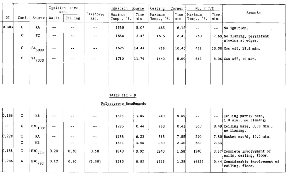
A third source, used for testing the more resistant foams and coated conventional materials, was a compact crib made from strips of 5/8-in. phenolic-bonded aspen flakeboard (density approximately 40 lb/cu ft). The crib consisted of 12 layers of 5 sticks,
1-3/16 by 12 in. in size, laminated with polyvinyl acetate emulsion glue. The typical weight of the finished cribs at 35 to 40 per cent R.H. was 6.0 ±0.2 kg. The cribs were supported on fire-bricks and an expanded metal mesh stand to bring the top to approximately the same level as that of the metal containers and to ensure adequate air supply to the igniting combination of 60 to 70 gm of dry excelsior and 20 to 30 ml of 95 per cent ethanol (Fig. 5). This system was designated Source PC.
In the later stages of the work, a natural gas burner with a wide range of potential fuel input was considered as a replacement for the three "natural" sources. The design of the burner was suggested by some unpublished work carried out by Parker of NBS while working at ULI. He used a 4- by 4-in. sand burner of
unspecified internal construction in a miniature corner wall test. The sand burner used in DBR tests (Fig. 6), designated Source SB,
is a 12- by 12- by l2-in. box of 10-gauge steel. The I-in. supply line feeds into a 3-in. deep plenum. Supported on 3/4- by 3/4-in. angle iron flanges above this are an expanded metal mesh support, a 20-gauge perforated plate (1/8-in. openings on 3/l6-in. centres), followed by a bed of natural gravel 1 1/4 in. thick (through 3/8 on 1/4-in. screens), a piece of copper window screen, and 5 in. of coarse sand (through 8 on 16 mesh). Strips of Type 36 Marinite, 3/4 in. thick by 1 in. deep, were fastened to the top edges of two adjoining sides of the box to prevent direct contact with the specimen. This also facilitated mounting of a suitable spark ignition source.
The reproducible range of flow rates, as measured by a Dwyer No. 25 Flex-Tube manometer and a 5/8-in. orifice plate calibrated against the test dial of a large gas meter, was from 1.5 to 12 scfm. The calorific value of the gas was between 1000 and 1020 Btu/scf.
It was hoped that the three existing sources could be matched by appropriate inputs to the sand burner, but it soon became obvious that the latter's characteristics made a reasonable match improbable without extensive testing.
Typical durations and temperatures for the first three sources are given in Table II. The blank tests were carried out with the source in its normal position against the asbestos-cement board walls. Temperature readings were taken 9 in. above the top of the container or crib and 2.5 in. out from both walls, as well as 6 in. below the ceiling and 2.5 in. out from the walls, using bare
26-gauge chromel/alumel thermocouples (Nos. 1 and 2). In the case of the sand burner the fuel input is indicated by the appropriate subscript, e.g., SB
5000 (5000 Btu/min. input).
Ventilation of the 40- by 40- by 40-ft burn area in which the tests were conducted was provided during all runs by means of one 6,000-cfm fan directly above the corner wall setup with two
interior doors opening into large adjacent laboratory areas. Arrangement of Material in Corner Wall Tests
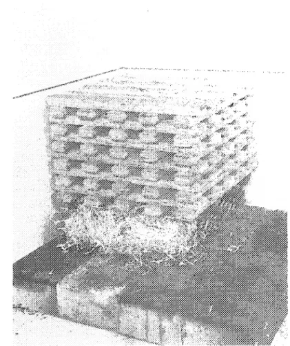
It was intended that all materials, regardless of FSC or SD, be tested initially in the standard USFPL arrangement ( 2- by 8-ft panels on the walls, 4-ft-wide "L" on the ceiling) which will henceforth be called Configuration A (Fig. 7). Where the amount of material available was limited, or if very rapid flashover and heavy evolution of toxic smoke were expected, the material on the ceiling was reduced to a 4-ft square. This is Configuration C
(Fig. 9). In Configuration B, the arrangement in A was augmented by 2- by 6-ft panels extending from the 2- by 8-ft wall panels to the sides of the canopy (Fig. 8). In Configuration D, used only in Test No. 28 of material 8-1 (Table III-B) with the I-mil foil
facing intact, the ceiling was the 4-ft-wide "L" of Configuration A, the wall panels were 4 by 8 ft, and 2- by 4-ft panels extended from these to the sides of the canopy, to maximize reflectance and
possible lateral spread (Fig. 10).
In some cases the larger area of ceiling material in Configuration A might have induced full and definite flashover where only partial flashover and retrogression actually occurred with the same material in Configuration C, as in Test 42, material 17-1, Source KB, (Table III-D) and Test 52, material 7, Source KB
(Table III-A). This has not yet been determined, however, as the amount of material available from these lots was limited.
Test Procedure
The basket sources were ignited by means of a propane torch; the timing of the test was started when the container was pushed into close contact with the walls. In testing with the particle-board crib PC, timing was started when the excelsior was ignited. The crib was usually fully involved in 2 min. or less. In the case of polystyrene beadboards, some tests with Sources KA and KB were followed by tests using 750 or 1000 gm of dry excelsior distributed in a 6-in. roll along the full width of the bottom of the 2-ft wall panels, and identified as EXC
750 or EXCl OOO' Recording of the temperatures at the eight thermocouples, including the one above the ignition source (No.1) and that at the corner 6 in. below the ceiling (No.2), was carried out by means of a Thermoelectric FMW06B 24-point recorder. Each
thermocouple was read three times per minute, with chart speeds of either 2 or 4 in./min., depending on the anticipated length of the test. Temperatures above the source and below the ceiling at the corner (Nos. 1 and 2) were also read independently by a Leeds and Northrup type 6 "Speedomax" at 8 prints per minute as insurance against failure or fouling of the other set of thermocouples in the hottest locations.
Visual observations of the progress of tests were backed up by videotape recordings of 36 of the 66 runs. On playback these usually gave more reliable readings of ignition times and flame heights than the observer's stopwatch records. Because of the position of the camera and the heavy smoke in some cases,
determination of flashover was usually visual but again, due to heavy smoke, evaluation was often dependent on the reading at No. 7 thermocouple. There were several borderline cases in tests of foams where flames did not appear to reach No. 7 thermocouple or, if they did so, did not produce the expected temperatures because of the low fuel contribution of the foam, or fouling of the
Results
The results of the 66 corner wall tests to date, with
supporting E84 and oxygen index data, are summarized in Tables III and IV.
Except in the case of the conventional materials and the most highly flammable foams, estimation of the visual time to flashover to less than ±0.05 min. is perhaps not justifiable. In some cases of moderately severe flashover followed by retrogression, the time to maximum temperature at No. 7 thermocouple agreed very closely with the visual estimate of flashover time. When ignition times were not determined by playback of a videotape they were usually the average of the readings by two observers.
1. Conventional Materials (Table III-A)
The most common characteristic of those cellulose materials which produced a definite flashover as determined visually or as indicated by a maximum temperature at No. 7 thermocouple of 1000 deg. F or over, was a funnel-shaped burn pattern on the side walls if the fire was extinguished before destruction had proceeded too far. This was particularly true of the raw and painted fibreboards
(materials 1 and 2) and the aspen plywood (material 4). Polyurethane foams, on the other hand, if the sidewalls were the usual 2- by 8-ft size, typically produced a narrow parallel-sided burn pattern,
sometimes only 12 in. wide at the 7-ft mark unless downward propag-tion was allowed to continue after a sustained flashover.
A larger amount of material on the ceiling (Configuration A vs. Configuration C) does not always produce a more rapid flashover or higher ceiling temperatures (Tests 56 and 57, Table III-A); this may have been due to variability in the source or in the finished fibreboard.
The influence of surface texture and internal structure are apparent in comparing Test 8 (medium-density fibreboard, FSC 118) and Test 22 (aspen plywood, FSC 150), which have similar densities but widely different flashover times with identical configurations
(A) and fuel sources (KA).
The most interesting results are those for Test 54 (factory-finished fibreboard, FSC 94) and Test 52 (1/2-in. fir plywood, FSC 90) in which flashover did not occur with Source KB and Configuration C. These behaved very similarly and flashover might have occurred in either case if there had been more material on the ceiling.
2. Laminates (Table III-B)
These present a more complex picture than boardstock foams. The FSC values quoted refer to tests with the foil intact, except
in the case of material 8-3. As already mentioned, removal of the foil does not significantly change the E84 rating for foams of 25 to 45 FSC.
The variability from lot to lot of material 8 (the exact age of all lots was unknown), and the higher flammability of the top surface when the foil was removed, are evident. Thus the influence of the "skin" is important even in a polyisocyanurate foam of
oxygen index 0.263.
The modified polyurethane foam (material 9) represents a distinct advance in foam technology. Again the top surface
appears to be more flammable than the bottom even in this product. 3. Boardstock (Table III-C)
The boardstock type, which is considered of limited future importance in the Canadian market, presents a relatively straightforward picture. In no case was the age of the foams known with any degree of certainty, and age and density may affect the fire behaviour as well as the physical properties of
fluorocarbon-blown foams. The slow and moderate flashover
exhibited by material 11-1 in Test 27 could not be repeated with the second lot, even on exposure to the sand burner at 7700 Btu/min., which caused severe damage by the end of the test.
Material 12-3 would be expected to be much less vulnerable than material 13, as suggested by the comparative flashover times with Source KA. On flashover, however, material 12 typically
disintegrated and fell from the ceiling and upper part of the walls in large flaming sheets. In contrast, damage to material 13 was confined to a thin surface layer on the ceiling, with shallow fissures running across the charred areas and deeper penetration only occurring at the inner corner of the ceiling at the time the test was terminated at 0.56 min. by means of a dry chemical
extinguisher. Tests 15, 45 and 69 show the effect of increasing intensity of the source on flashover time with material 12
(Table III-C).
4. Sprayed Foams (Table III-D)
This category presents the greatest difficulty in
interpretation of results and assessment of relative hazard. The influence of the heavy "skin" on such foams may be a major factor in their behaviour. The protective effect of the intumescence
which develops counteracts the apparently high ignitability of the "skin" in the case of materials 15 and 17. Flashover is followed by retrogression with these foams, but might have been more sustained and extensive with more material on the ceiling
(Configuration A or fully-lined ceiling).
Test 25 (material 14) is a good example of anomalous behaviour. In spite of an FSC of 18 and an 01 of 0.265, this material produced a real flashover after the flames had first receded to between 2 and 3 ft in the corner. Material 15-1 (Test 24) with an FSC of 30, performed as well with Source KA as
material 14, a boardstock of FSC 20. The variability in
properties of sprayed foams is obvious. It is unfortunate that more of material 14 was not available.
Although the sand burner leaves much to be desired as a variable replacement for the natural sources, the results of Tests 71 and 72 (Table III-D) indicate that an improved gas burner might be acceptable as the source in a standardized corner wall test.
5. Phenol-Formaldehyde Boardstock (Table III-E)
This type offers a material of high insulating
properties and chemical inertness useful in comparing ignition sources with minor fuel contribution by the specimen. No visible flaming was observed during any tests on this foam, but sustained glowing combustion ("punking") with minimal smoke emission along the edges of fissures and holes continued indefinitely after the ignition source was removed, unless extinguished by water spray. Tests 20 and 68 (Table III-E) suggest that, for foams of low FSC and high insulation value such as this, the sand burner at 7000 Btu/min. input is roughly equivalent to the particleboard crib. 6. Polystyrene Foams (Table III-F)
The rapid melting and dripping which make the results of E84 tests of polystyrene foams questionable are also a source of uncertainty in evaluating these foams in the corner wall test.
For beadboards 1.0 in. thick, either regular or "self-extinguishing", the speed of shrinkage away from the plume or dropping of irregular masses of material from walls and ceiling depended on the intensity of the source. Ignition was limited to molten material adhering to nails or washers which in turn dripped and ignited unmelted material on the floor.
The 2-in. beadboards (materials 22 and 23) exhibited much more involvement. With 750 gm of excelsior as the source, the "regular" material (22) ignited over the whole wall and ceiling
surface before major dripping could occur, with flashover at 0.5 min. and complete removal of material from walls and ceiling at 0.6 min. The 4- by 4-ft surface of the 2-in. mineral insulation board used on the floor was completely covered by small discrete burning pools of the material which had fallen as liquid droplets from the ceiling.
The "self-extinguishing" material (23), with the same source, ignited more rapidly than the "regular" grade, but the apparent flashover occurred at 1.5 min. The walls were completely bare at 2.3 min. and the ceiling at 3.0 min. Material falling from walls and ceiling was ignited by the excelsior to a distance of approximately 1 ft from and 4 ft along the base of the walls. 7. Painted Foams (Table IV)
Tests 35 and 43 show that the UL-listed intumescent latex paint T is more effective on factory-finished fibreboard than on a 40-FSC urethane boardstock. Paint F intumesces more deeply at
lower temperatures than T and is more effective than T on the 40-FSC urethane foam. It is not as effective in protecting a high FSC foam (material 10, foil/kraft face removed) as a less
flammable foam. Because of its lower cost, it could be applied at lower coverages (heavier films) and offer substantial flash
protection to readily ignitable foams such as material 18. Discussion
The trenchant criticisms of the E84 test as applied to some foams are amply justified. (These are even more justifiable in the case of ASTM 01692.) For polyurethane boardstock above 2S FSC, the E84 test is misleading, as the corner wall tests show. Whether there is some reproducible FSC value between 2S and 40 where a sharp change in corner wall performance occurs is yet to be determined. The 01 (oxygen index) values suggest that no boardstock or sprayed foam is likely to give an FSC value of 2S or less unless the 01 is 0.26 or higher.
In the case of laminates, the performance of the material with the foil removed in the corner wall test cannot be readily predicted from the 01 or FSC. The influence of the "skin" and the chemistry of the formulation are probably more important in
governing this behaviour. Ranking of laminates with foil intact, given a suitable corner wall test, will probably be subjective under the best of conditions. This will probably also be true of light coatings on board stock or spray formulations.
The evaluation of sprayed foams by E84 or corner wall tests will be difficult because, in addition to the influence of the "skin," the degree of intumescence in either test may govern
their nominal ratings. As already suggested, the use of a corner wall test with more material on the ceiling, a corridor-corner test or a room burn test may be necessary to rank bare or coated sprayed foams satisfactorily.
The restrictions imposed by the U.S. Federal Trade
Commission on producers' claims regarding the fire performance of their foamed plastics as based on existing standard tests are amply justified in the case of many low-density foams, but not of phenolic or urea-formaldehyde types. The heavily funded research work mandated by the Federal Trade Commission should help to explain the anomalous behaviour of polyurethane foams.
As Roberts1 2 has pointed out, the "thermal inertia" (the product of conductivity, heat capacity and density) of beechwood is 100 times that of a 2.5 lb/cu ft polyurethane foam. Thus the surface of the urethane foam "would achieve a particular surface temperature in 1/100 of the time taken by beechwood when heated by a constant heat flux." The activation energy of
decomposition of Roberts' foam (a highly flammable formulation with tris-trichloroethyl phosphate added) was 270 kJ/mol as
opposed to 63 kJ/mol for beechwood. These differences in physical and chemical properties are complicated by the formation of a protective char in the case of this foam. If the char is
intumescent, prediction of performance, as already noted, may be even more difficult. Funt and Magill13 emphasize the importance of the formation of a coherent intumescent char in protecting the underlying material in a nominally high flammability foam. All DBR observations of E84 tests of polyurethane foams confirm the importance of the char, regardless of its real thermochemical characteristics (heat of combustion, 01 under tunnel conditions, etc.). The typical behaviour of a polyurethane foam of high FSC
(300 to 1000) is a flash to the end of the tunnel, sometimes followed by a second flash to the end or within 1 or 2 ft of it, then rapid retrogression to 2 to 3 feet from the zero mark. After this retrogression the degree of attack on the foam beyond the impingeing burner flame is usually slight unless the foam
intumesces or exfoliates markedly during the first advance down the tunnel. In tests of foams of 20 to 55 FSC, the time to
maximum flame spread varies from 1.5 to 4 min., and retrogression is gradual. It would be interesting to compare materials 12 and 13, 15 and 17 in large-scale corridor or room tests because of their marked differences in behaviour in the E84 and corner wall tests.
The issue of the evaluation of polystyrene foams will not be fully discussed here as it obviously requires a different
approach. Hard data on the performance of both ーッセケウエケイ・ョ・ and. polyurethane foams behind thermal barriers is requlred to put ln proper perspective statements by some authorities on the
contribution of these foams to fully developed fires.
---The most common application of exposed polystyrene foam is in residential basements, where the householder, who may be uninformed as to the grade of foam (regular or SE) that he is using, may leave it unprotected for reasons of cost or appearance. From the few corner wall tests described in this report, it is evident that 2 in. of material is more hazardous than 1 in., given a sufficiently large source, and that even 2-in. SE material will burn under the right conditions as the volatile retardant is driven off. Conditions admittedly might be such that the room might not be habitable anyway, but covering of the foam would reduce the initial smoke and fuel contribution even if total integrity of the covering is not maintained.
Conclusions
This report emphasizes the pronounced differences in performance in the DBR/NRC corner wall test between conventional cellulosic lining materials and polyurethane foams of nominally similar FSC's in the 40 to 100 range. The limitations of the E84 test in this range and the necessity for caution in the evaluation of coated foams by this method are obvious.
The DBR/NRC version of the corner wall test is a step in the development of a standardized test for foams. It has been adequate as an ad hoc test in indicating the complexity and scope of the problem, particularly as it touches on sprayed foams, laminates and painted boardstock. The inevitable variability of sprayed polyurethane foams presents a quality control as well as a fire testing problem. With the rapid advance in urethane foam technology now in progress and the development of economical protective coatings, the ranking of unprotected foams, even
sprayed types, in the 40 to 100 FSC range may cease to be relevant in the near future, and approaches more complex than the simple corner wall may be required. The recent work of Draemel and Williamson supports this conclusion.1 4 The design of a "second generation" corner wall arrangement, as urged by the ULC Fire Tests Committee, is underway and a putatively superior sand burner has already been tested.
Although much more work is required to establish its limitations, the oxygen index test may be a valuable screening tool for modified polyurethane foams. In addition to the 01 test, there appears to be a requirement for a small-scale test that will evaluate the interaction of polymer structure and retardants as measured by the 01, and the protective value of surface char or intumescence. It is possible that Smith's RHR (rate-of-heat-release) method1 5 may be useful in this regard.
REFERENCES 1 2 3 4 5 6 7
ASTM E84-70. Standard Method of Test for Surface Burning Characteristics of Building Materials.
ASTM D1692-74. Standard Method of Test for Rate of Burning
of Cellular Plastics Using a Horizontally Supported Specimen. Rose, A. Flammability of Lining and Insulating Materials,
National Research Council of Canada, Division of Building Research, CBD 141, Ottawa, September 1971.
ASTM D635-74. Standard Method Test for Flammability of Self-Supporting Plastics.
ASTM D30l4-74. Standard Method Test for Flammability of Rigid Cellular Plastics.
ASTM D2863-l974. Standard Method of Test for Flammability of Plastics Using the Oxygen Index Method.
Maroni, W.F. Rigid Cellular Plastic Wall Insulation. Fire Journal, Vol. 66, No.6, November 1972.
8 Fire Test Methods Used in Research at the Forest Products
Laboratory, Forest Products Laboratory, U.S. Dept. of Agriculture, Report No. 1443 (revised September 1959), Madison, Wisconsin. 9 10 11 12 13
ASTM E286-69. Standard Method of Test for Surface Flammability Using an 8-ft. (2.44 m) Tunnel Furnace.
ASTM E162-67. Standard Method of Test for Surface Flammability Using a Radiant Heat Energy Source.
Gross, D. and Fang, J.B. The Definition of a Low-Intensity Fire. National Bureau of Standards, Special Publication 361, Vol. 1: Performance Concept in Buildings, Procs. of the Joint RILEM-ASTM-CIB Symposium, May 1972,
Philadelphia. p. 677-686.
Roberts, A.F. Polyurethane Foam: Some Studies Relating to Its Behavior in Fires. Fire Technology, Vol. 7, No.3, August 1971.
Funt, J.M. and Magill, J.H. Estimation of the Fire Behavior of Polymers, Journal of Fire and Flammability, Vol. 6, January 1975.
14
15
Draemel, R.B. and Williamson, R.B. Review and Testing of Fire-Protective Coatings for Polyurethane Foam. NASA Contract NA52-8288, December 1974.
Smith, E.E. Heat Release Rate of Building Materials, ASTM STP 502, 1972.
I. Conventional Finish Materials
Material Thickness, Density, ASTM E84
No. Type in. lb/cu ft FSC SO
1-1 Unfinished fibreboard 0.43 19.2 97 124 1-2 Unfinished fibreboard 0.43 100 103 2-1 Factory-finished fibreboard 0.43 18.2 103 28 2-2 Factory-finished fibreboard 0.43 19.9 94 95 2-3 Factory-finished fibreboard 0.43 18.6 100 62 3 Medium-density fibreboard, unfinished 0.47 26.2 118 119
4 Aspen plywood, 5-ply,
phenolic glue 0.50 28.9 150 175 5-1 Unfinished hardboard siding 0.35 56.3 148 300 5-2 Unfinished hardboard siding 0.35 58.7 138 218 6 Laminated fibreboard, F.R. Paint 0.25 36.0 81 133
7 Douglas fir plywood,
II. Laminates (nominal 1.0 in.) Material No. Type Density, lb/cu ft ASTM E84 FSC SO 01* 8-1 Polyisocyanurate,
alum. foil faced 2.0** 25 200 0.263
8-2 Polyisocyanurate,
alum. foil faced 2.3** 25 218
8-3 Polyisocyanurate,
30t
alum. foil faced 2.0** 212
9 Polyurethane,
alum. foil faced 2.90** 20 315 0.263
10 Polyurethane, alum.
foil/kraft faced 2.81** 723 215 0.218
III. Boardstock (nominal 1.0 in.)
ll-l Polyisocyanurate 1.97 20 160 0.264 11-2 Polyisocyanurate 2.04 23 159 0.260 12-1 Polyurethane 1.97 40 114 12-2 Polyurethane 1.77 0.237 12-3 Polyurethane 1.82 55 150 0.237 13 Polyurethane 2.06 50 160 0.208
* Oxygen Index (ASTM 02863-74) ** Density with foil removed.
t
IV. Sprayed Foams
Material Thickness Density. ASTM E84
No. Type in. lb/cu ft FSC SD 01
14 Polyisocyanurate (1. 0) * 2.10** 18 360 0.265 15-1 Polyurethane (1. 0) * 2.10** 30 323 15-2 Polyurethane (1. 0) * 2.10** 23 444 0.259 15-3 Polyurethane (1. 0) * 2.70 65 456 0.241 16 Polyurethane (1. 0) * 2.10** 50 370 0.227 17-1 Polyurethane 1. 25 2.44 38t 610 0.251 17-2 Polyurethane 1.25 2.41 65 558 0.233 18 Polyurethane 1.0 2.47 45 442 0.220 V. Phenol-Formaldehyde Foam 19 Boardst6ck 1.0 3.20 20 5 0.383
VI. Polystyrene Foams
20 21 22 23 Regular beadboard SE beadboard Regular beadboard SE beadboard 1.0 1.0 2.0 2.0 0.92 1.00 1.05 0.81 0.188 0.270 0.188 0.286
* Variable thickness. average given. ** Producer's estimated average.
Ignition Sources - Blank Runs At Ceiling Designation KA KB PC Above Maximum Temp , , of. 1440 1600 1760 Source Time, Min. 7.15 3.60 16.80 Maximum Temp , , of. 380 685 1370 Time, Min. 8.00 3.35 13.15 Effective Duration, Min. 12-13 4-5 18-25
Conventional Materials
Ignition Time, Ignition S,ource
I
Ceiling, Corner No. 7 TiCmin.
Maximum ITime, Remarks
Test セャ。エ・イゥ。ャ Flashover Maximum ; TIme セi。クゥュオュ Time
No. No. FSC 01 Conf. Source Walls Ceiling min. Temp. , o f '' .rninセ ,Temp., of. mi.n , Temp., of. min.
34 1-1 97 C KA I 0.75 1.65 2.00 1500 I 4.70 1675 4.58 1540 3.20 Temp. 1135 at flashover I
I
(No.7 TiC) 9 2-1 103 A KA 1.48 4.15 7.80 1630 7.73 i 1685 7.08 1530 8.24 Temp. 1390 at flashover 10 2-1 103 B KA 0.98 4.48 7.30 1560 7.60 1720 7.20 1475 6.89 54 2-2 94 C KB 1.15 2.00 -- 1670 4.67 1575 4.15 705 8.07 Spread 2 ft radially, 4 ft along ceiling.56 2-3 100 A KB 1.06 2.70 8.75 1630 3.28 1615 8.60 1400 8.75 Flames out vents, 5.5 min.
57 2-3 100 C KB 0.90 2.00 4.00 1660 4.30 1595 4.60 1165 4.00 Moderate flashover 8 3 119 A KA 0.92 2.48 3.50 1430 2.15 1800 4.40 1180 3.34 22 4 150 A KA 5.10 7.95 9.00 1325 10.10 1545 8.71 1425 10.10 53 4 150 C KB 0.60 1. 84 3.10 1720 1.95 1630 5.38 1510 4.30 21 5-1 148 A KA 4.10 7.10 8.25 1430 5.40 1490 7.54 1445 8.45 51 5-2 138 C KB 2.20 3.40 5.50 1590 4.92 1575 5.82 1440 6.43 Moderate flashover, 805 of at 5.5 min. (#7) . 11 6 81 C KA 6.10 -- -- 1445 2.55 380 5.21 n.d. n.d.
41 6 81 C PC -- -- -- 1770 16.50 1520 9.32 760 1.80 Crib ext'd at 18.0 min.
52 7 90 C KB 2.64 3.33 -- 1675 4.19 1590 4.05 790 3.90 Flames receding from
Po1yisocyanurate/Po1yurethane Laminated Boards
Ignition Time, Ignition Source Ceilinll, Corner No.7 T/C
Test Material min. Flashover Maximum Time Maximum Time Maximum Time) Remarks
No. No. FSC or Conf. Source Walls Ceiling min. Temp., of. min. Temp .• of. min. Temp., of. min.
13 8-1-X-T 25 0.26 C KA 0.85 -- -- 1485 1.88 525 7.20 --
--18 8-1-X-T C PC 4.50 -- 7.10 1680 8.15 1610 5.74 995 5.10 Slow crib, weak flashover.
19 8-1-X-T 0 PC 4.70 7.95 8.05 1700 8.45 1600 8.45 1575 8.45 Ext'd at 8.5 min.
26 8-1-X-T A-I· PC 1. 45 2.57 2.75 1635 2.82 1705 3.30 1550 3.15 Ext'd at 3.83 min.
28 8-1-F-B B PC -- 4.00 -- 1850 10.92 1675 4.65 950 8.00 No definite flashover; fire
at vents 4.95 min.
32 8-1-X-T C KB 0.68 0.88 2.60 1760 4.26 1785 2.95 1245 2.90 Flames receded
0.88 - 1.75 min.
46 8-2-X-T 25 -- C KB 0.95 1. 25 1. 33 1735 1.33 1710 1. 20 1400 1.47 Flames receding from
ceiling at 1.85 min.
47 8-2-X-B C KB 0.62 -- -- 1545 2.38 1030 3.65 435 3.60 Flames receding from
ceiling at 1.02 min.
49 8-3-X-T 30 -- C KB 0.52 0.90 1.15 1580 2.10 1505 1. 50 1485 1. 22
50 8-3-X-B C KB 0.35 0.75 2.70 1650 0.78 1755 2.80 1190 2.82 Flames receded after
moderate flashover.
60 9-X-T 20 0.26 C KB 0.25 0.60 -- 1590 4.12 1305 0.88 450 1.04 Flames laterally
left on ceiling.
61 9-X-B C KB 0.20 -- -- 1675 3.93 935 0.72 405 2.90
62 9-X-B C PC 2.65 -- -- 1610 3.81 1600 6.93 540 7.70
74 9-X-T A PC 1.95 -- -- 1485 3.75 1540 8.45 750 7.68 Crib ext'd at 10 min.
75 9-X-T A SB
7700 0.08 0.10 0.30 1605 3.92 1355 0.60 1000 0.30 Flames receded
after flashover
Ignition Time, Ignition Source Ceiling, Corner 1'0. 7 TiC
Test Material min. Flashover Maximum Time Maximum Time Maximum ITime, Remarks
No. No. FSC 01 Con f , Source Walls Ceiling min. Temp., of. min. Temp., of. min. Temp., of. min.
14 11-1 20 0.264 C KA 0.60 -- -- 1500 6.33 625 6.50 -- -- Se1f-ext'd, 10.0 min.
33 11-1 20 C KB 0.28 1.38 -- 1630 3.87 1275 1.75 555 1.70 s・QヲM・クセG、L 5.22 min.
27 11-1 20 B PC 1. 69 3.00 4.50 1640 2.80 1610 4.65 945 4.71
65 11-2 23 0.26C C SB5000 -- -- -- 1580 1.56 825 2.97 395 1.33
66 11-2 23 C PC 2.80 -- -- 1710 4.90 1615 9.17 -- -- Crib ext'd at 10 min.
76 11-2 23 A 5B
7700 0.02 0.07 -- 1600 1.36 1510 0.48 620 0.40 Very minor ignition, burner
ext'd 5.0 min.
15 12-1 40 -- C KA 0.50 1. 78 2.00 1465 1.38 1215 2.00 1190 2.06
45 12-1 40 -- C KB 0.50 0.64 0.85 1580 0.91 1165 0.86 1270 0.94 Flames beyond canopy 0.94 min
69 12-3 55 10·23 A 5B5000 0.04 0.10 0.25 1390 -- n.d. n.d. 1425 0.23 Burner ext'd 0.42 min.
73 13 50 0.208 A KA 0.24 0.30 0.40 1385 -- 1410 -- 1350 -- Ext'd 0.56 min.
Polyisocyanurate/Polyurethane Sprayed Foams
Ignition Time, Ignition Source Ceiling, Corner No. 7 T/C
Test Material min. Flashover Time Maximum Time Maximum ITime, Remarks
ICeiling
Max imum
No. No. FSC 01 Coni. Source Walls min. Temp .• of. min. Temp., of. min. Temp .• of. min.
25 14 18 O.RVセ C KA 0.20 5.30 5.40 1465 6.20 1550 5.87 1185 6.14 Flames receded at 2.85 min.,
then increased.
24 15-1 30 -- C KA 0.25 -- -- 1390 0.67 680 0.77 -- -- Self セクエG、 12.2 min.
36 15-2 23 セNRUY C KB 0.40 0.94 (0.95) 1845 2.60 1530 0.95 810 0.94 Receded at 1.0 min., after
mild flashover.
70 15-3 65 セNRTQ C KB 0.40 0.70 1. 00 1335 1. 80 1395 1.04 925 0.97 Receded after flashover,
self-ext'd 7.25 min.
71 15-3 C SB5160 0.03 0.10 0.30 1390 0.48 1410 0.48 1145 0.42 Receded after flashover,
gas off 2.10 min.
72 15-3 C SB
3000 0.15 0.25 0.50 1365 5.00 1410 0.55 785 0.48 Partial flashover, receded
at 0.60 min.
23 16 50 セNRRW C KA 0.15 0.35 0.50 1565 0.44 1425 0.79 1480 0.79 Ext'd at 0.79 min.
42 17-1 (38) P.251 C KB 0.30 n.d. (0.85) 1465 1.87 1405 0.96 1060 0.84 Receded after flashover,
heavy intumescence.
64 17-2 65 P.233 C KB 0.35 n.d. 0.70 1400 1.50 1370 0.80 1200 0.80 Receded after flashover,
self-ext'd 6.75 min.
Ignition Time. Ignition Source Ceiling, Corner No. 7 TIC
min.
Time, Remarks
Test Material Flashover Maximum Time Maximum Time Maximum
No. No. FSC 01 Conf. Source Wall s Ceiling min. Temp., of. min. Temp., of. min. Temp . , of. min.
12 19 20 0.383 C KA
--
-- -- I 1530 5.07 485 6.15 -- -- No ignition.20 19 C PC -- -- -- 1850 12.47 1615 8.40 780 7.69 No flaming, persistent
glowing at edges.
67 19 C 5B5000 -- --
--
1625 14.48 855 10.40 435 10.38 Gas off, 15.5 min.68 19 C 5B7000
--
----
1710 11.70 1440 8.00 665 8.06 Gas off, 15 min.TABLE III - F Polystyrene Beadboards
39
I
20I
--
b.1881 C KBI
-- -- --I
1525 I3.85 740 I 8.451 -- -- ICeiling partly bare,l.0 min., no flaming. 40 I 20
I
--
I --I
C IEXCl OOO -- -- -- 1285 0.44 780 0.41 530 0.49 Ceiling bare, 0.50 min.,
no flaming. 37
I
21
I
--r·
2701C KA -- -- -- 1235 6.23 365 7.85 220 7.80 Basket ext'd, 10.0 min.
38 21 -- C KB -- -- -- 1375 3.98 560 2.30 365 2.53
48 I 22 I -- b.188l C EXC750 0.20 0.30
050
1::
0.92 1240 1.58 1240 0.57 Complete involvement of walls, ceiling, floor.
55 23 -- b.2861 A IEXC750 0.12 0.20
Painted Foams
i Igm t. .ion T'ime , iI Fl : h- Ignition Source Ceiling Corner, NO.7 T/C
Test Painti Coated Foam Min. I over,as Time, セャ。クゥュオュ Time, Maximum i .TIme, Remarks
No. Mat'l FSC SO Type Coverage* FSC SO Conf , Source \\'a11 Ceiling I
Min . Temp., of. セQゥョ . Temp., of. Min . Temp., of. Min.
35 2-1 103 28 T 250 74 62 C PC I 5.10 6.50 -- 1710 2.49 1510 8.75 1015 10.7C 43 12-1 40 114 T 205 -- -- C KB 1. 20 1. 75 (2.00) 1715 1. 70 1355 1.95 1250 2.4C Light flash-over 44 12-1 40 114 F 190 -- -- C KB (1. 70) -- -- 1690 3.80 1185 3.14 485 3.2 59 12-2 -- -- F 255 60 153 C KB (2.10) -- -- 1665 4.75 815 2.10 400 2.3 63 12-3 55 150 F 250 35 250 C PC 3.55 4.50 5.25 1520 2.45 1690 5.60 925 5.5( Ext'd 5.75 min. 58 lOX" セWU 215 F 282 278 318 C KB 1.10 2.80 3.45 1475 2.75 1525 3.25 1450 3.7 Ext'd 3.75 min. 78 18 45 442 F 115 -- -- C SB
5000 1.60 -- -- 1550 7.10 1010 1.72 420 6.03 Gas off,8.0 min.
I , i
* In sq ft/imp. gal.
I
,
I \ No. 2 \ \ \e
No.3 \ \ 1 ' Thermocouple \ \ \ \ -, 6" Be low \ \ \ \ \ 2 ' <, \ Sample \ \ \ 5 ' \ 4' \ 3 ' \ \6' \ \ -, \7' \ \ \ \ <, ... \ \ \ \ \.eN o. 4 \ \ \ \ -, <, \ \ \ \ <, \. ... \ \ \ No.5" \ -, \ \,
<, <, \ \,
No.7 -, <,e
... "----<, Are a Covered With <, <, 1/4" Superbestos <, -, ... --,
---, <, ... ... _ No.8
- - - e
Flue ...--
---lNorth
"---FIGURE 2
Figure 3. Source KA ., 1['. セZ ;' Ij I!
I
h ::: Figure 4. Source KBセ
...Figure 8. Configuration B