Chapter 6. Chemical Beam Epitaxy of Compound Semiconductors
Chapter 6. Chemical Beam Epitaxy of Compound
Semiconductors
Sponsors
Joint Services Electronics Program (Contracts DAAL03-86-K-0002 and DAAL03-89-C-0001)
U.S. Navy - Office of Naval Research (Contract N00014-88-K-0564) Academic and Research Staff
Professor Leslie A. Kolodziejski
Graduate Student
Dana I. Lee
6.1
Introduction
The new facility for the chemical beam epitaxy of compound semiconductors (both Il-VI and III-V materials) represents a major addition to RLE and is currently undergoing extensive laboratory construction. A spe-cially designed, one-of-a-kind multichamber chemical beam epitaxy (CBE) system is
under development by EMCORE Corporation and is scheduled to be completed in August
1989.
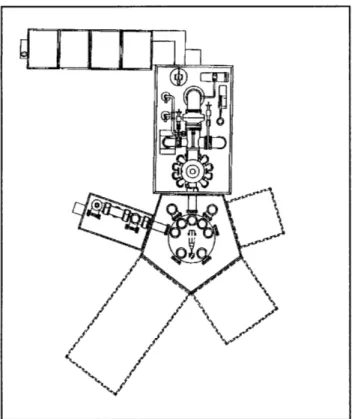
A schematic drawing of the new CBE facility is shown in figure 1. In addition to the growth chamber, the system has 1) an intro-duction chamber, which is capable of accepting five separate 2 inch wafers, 2) a bakeout chamber, which is required to clean the sample holders prior to mounting the substrate, and 3) an ultrahigh vacuum transfer module. The entire process will be computer controlled via a sophisticated MASSCOMP computer, which is complete with customized software. The transfer module contains a high temperature stage for thermal processing of substrates, an elevator for multiple wafer storage, and has additional porting such that five separate ultrahigh vacuum chambers may be added in the future; the expansion could include growth chambers, a metalization chamber, or in situ processing chambers. Porting is also avail-able to add various sample stages, which would allow any necessary manipulation of each wafer between various processing steps (such as transferring the wafer from one sample holder to another, etc.). Transfer of
each wafer from one ultrahigh vacuum
process chamber to another will be carried
out
by a computer-controlled,
rotating
robotic arm.
Addition of an analytical
chamber, having Auger electron spectroscopy
(AES), is currently in the proposal review
stage, with plans to add electron
spectro-scopy for chemical analysis (ESCA) in the
near future. The necessary funds to acquire
the CBE system originated from support from
the Sloan Foundation, AT&T Bell
Laborato-ries, Office of Naval Research, National
Science Foundation, Army Research Office,
and Defense Advanced Research Projects
Agency, in addition to a substantial donation
from EMCORE Corporation.
The CBE growth chamber is equipped with
four individual gas injectors for metalorganics
of Zn, Ga, In, and Se, and for the hydride
arsine. (Each gas injector has the capability
of accepting four separate gases.)
Three
typical effusion cells, such as those used in
molecular beam epitaxy, are available for use
with
dopant
or alloying elements.
In situ
analysis facilities include reflection high
energy electron diffraction, a residual gas
analyzer and a quartz crystal flux monitor.
Specially designed heated quartz viewports,
have been placed so that a laser beam can be
both incident to, and reflected from, the
growing surface front. An argon ion laser is
available to perform visible and ultraviolet
laser-assisted epitaxial growth experiments.
As an extra safety precaution, the entire
growth chamber, pumping system and gas
Chapter 6. Chemical Beam Epitaxy of Compound Semiconductors
Figure 1. Schematic drawing of the layout of the chemical beam epitaxy system. The growth chamber, transfer module, and introduction chamber are shown with considerable detail, whereas the future expansion modules are only outlined. The approximate dimen-sions are 17 feet x 25 feet.
manifold panel is housed in a fully exhausted, laminar flow bench, providing a
"clean room" environment for the CBE facility. The introduction chamber will also be located in an exhausted, laminar flow hood to minimize any contamination from the laboratory and to protect the samples both before and after growth.
A 1200 square feet laboratory will house the epitaxy facility and is currently in preparation at MIT. Plans for the laboratory include a changing room to keep the environment rela-tively clean, in addition to a complete substrate preparation facility.
6.2
Controlled Substitutional
Doping of ZnSe Grown by
Chemical Beam Epitaxy
The II-VI compound semiconductor family, and the potential of these materials for optical device applications, have remained relatively untapped due to the substantial
dif-44 RLE Progress Report Number 131
ficulties in preparing the II-Vis, by any growth technique, to contain both p-type and n-type carriers. Bulk, liquid phase, or vapor phase growth techniques of the past used very high temperatures for the fabri-cation of ZnSe, and consequently control of the carrier type could not be achieved. The resultant ZnSe always exhibited n-type trans-port properties, or the as-grown material was so heavily compensated that the material was highly resistive. Newer growth technologies, such as molecular beam epitaxy (MBE) and chemical beam epitaxy (CBE), provide promise of circumventing the doping prob-lems of the II-VIs, and ZnSe in particular, due to the non-equilibrium nature of the growth, and by the ability to affect the growth, with photon illumination to cite one example. Once ZnSe is controllably doped as p-type and n-type material, many device applications are foreseen taking advantage of the wide, direct bandgap (2.67 eV at room temperature) which provides for the emission of blue light. Blue light emitting diodes, blue semiconductor lasers, and flat panel electroluminescent display devices are just a sampling of the many possible optical devices. The blue wavelength range will be useful in 1) visible holography and 2) laser disc recording, where a shorter wavelength would allow for a ten-fold increase in the density of stored information, and 3) for short range communications in which new
polymer fibers can be utilized.
Studies of dopant incorporation reported in the literature for ZnSe have been complicated by the presence of unintentional impurities found in both elemental and compound source materials used in the MBE growth process. In most cases undoped ZnSe grown by MBE, using commercially available source material, has been reported to be n-type with low resistivity (- 1 Q -cm). The low resistivity of the "undoped" ZnSe material implied that the ZnSe had good stoichiometry, as a relatively small deviation from a Zn-to-Se flux ratio of one-to-one, toward either Zn-rich or Se-rich conditions, was found to result in high resistivity material. (The defects generated during growth under non-stoichiometric conditions appeared to compensate for the non-intentionally incorporated impurities giving rise to the high resistivity.)
Chapter 6. Chemical Beam Epitaxy of Compound Semiconductors
Although major progress has recently been made in the molecular beam epitaxy of ZnSe, significant limitations still exist for the con-trolled substitutional n- and p-type doping. The many advantages of the growth tech-niques of molecular beam epitaxy and metalorganic chemical vapor deposition (MOCVD) are combined in CBE, while their many disadvantages are eliminated. The ultrahigh vacuum environment of the MBE technique remains in tact in CBE, but the solid source material is replaced by gaseous source material and is similar to MOCVD. The gas sources permit constant flux ratios at reasonable growth rates. By employing metalorganic gaseous sources for the Zn and Se species, a greater degree of control of the flux intensities will be obtainable than that possible by employing low temperature high vapor pressure elemental sources of Zn and Se, as in MBE. Because the elements origi-nate from a gas bottle, long-term operation is possible, since very little gaseous material is consumed. Many hardware problems encountered during the growth of II-VI com-pounds will be eliminated by employing chemical beam epitaxy. It is anticipated that the use of chemical beam epitaxy will allow the crystal growth problems to be overcome, so that scientists and device engineers can capitalize on the many attractive material properties of the Il-VI compound semicon-ductors. With research support from the Office of Naval Research, the CBE of ZnSe will be explored. The optimum growth parameters will be determined following microstructural, optical, and electrical evalu-ation of the epitaxial layers. Once high
quality, ultrapure, undoped ZnSe is achieved, the objective of the program supported under JSEP, is to address the incorporation of
impurity species in ZnSe.
In addition, chemical beam epitaxy is naturally suited for many experiments which are designed to modify or affect the epitaxial growth process. For example, impingement of either coherent or incoherent light of various wavelengths can effect the "nature" of the incident atomic or molecular species; the actual bonding configuration of the mol-ecules can determine their sticking coefficient and their incorporation. The effects of illumi-nating the growing surface front with a low power laser beam will be investigated.
The use of gaseous sources to replace high pressure solid sources will allow greater flexi-bility for utilizing the vacuum system for a variety of materials. Historically, the II-VI
and Ill-V, or group IV compounds have been grown in separate vacuum systems to elimi-nate problems associated with unintentional auto-doping of each material. Since each element originates from a gas tank external to the vacuum in CBE, the source oven and
material will not be contaminated with ele-ments of the opposite species. It is envi-sioned that both ultrapure II-VI and III-V
materials can be fabricated in the same vacuum system, since the II-VIs and Ill-Vs are not expected to form a compound until the metalorganics interact with the heated single crystalline substrate. Studies of various II-VI/Ill-V heterostructures of complex design and dimensions are now fea-sible and will be pursued.
Professor Jesus A. del Alamo (center) and students Sandeep Bahl (left) and Walid Azzam