HAL Id: hal-01292318
https://hal.archives-ouvertes.fr/hal-01292318
Submitted on 22 Mar 2016
HAL is a multi-disciplinary open access
archive for the deposit and dissemination of
sci-entific research documents, whether they are
pub-lished or not. The documents may come from
L’archive ouverte pluridisciplinaire HAL, est
destinée au dépôt et à la diffusion de documents
scientifiques de niveau recherche, publiés ou non,
émanant des établissements d’enseignement et de
Towards Resilient Computing on ROS for Embedded
Applications
Jean-Charles Fabre, Michaël Lauer, Matthieu Roy, Matthieu Amy, William
Excoffon, Miruna Stoicescu
To cite this version:
Jean-Charles Fabre, Michaël Lauer, Matthieu Roy, Matthieu Amy, William Excoffon, et al.. Towards
Resilient Computing on ROS for Embedded Applications. 8th European Congress on Embedded Real
Time Software and Systems (ERTS 2016), Jan 2016, TOULOUSE, France. �hal-01292318�
Towards Resilient Computing on ROS
for Embedded Applications
Jean-Charles Fabre1, Michal Lauer2, Matthieu Roy
CNRS-LAAS, Ave du Colonel Roche, F-31400 Toulouse, France
1Univ de Toulouse, INP, LAAS, F-31400 Toulouse, France
Matthieu Amy1, William Excoffon1, Miruna Stoicescu3
CNRS-LAAS, Ave du Colonel Roche, F-31400 Toulouse, France
2Univ de Toulouse, UPS, LAAS, F-31400 Toulouse, France 3Presently with ESOC/ESA, Darmstadt, Germany, on behalf of GMV
Abstract—Systems are expected to evolve during their service
life in order to cope with changes of various natures, ranging from fluctuations in available resources to additional features requested by users. For dependable embedded systems, the challenge is even greater, as evolution must not impair dependability attributes. Resilient computing implies maintaining dependability properties when facing changes. Resilience encompasses several aspects, among which evolvability, i.e., the capacity of a system to evolve during its service life. In this paper, we discuss the evolution of systems with respect to their dependability mechanisms, and show how such mechanisms can evolve accordingly. From a component-based approach that enables to clarify the concepts, the process and the techniques to be used to address resilient computing, in particular regarding the adaptation of fault tolerance (or safety) mechanisms, we show how Adaptive Fault Tolerance (AFT) can be implemented with ROS. Beyond some implementation details given in the paper, we draw the lessons learned from this work and discus the limits of this runtime support to implement such resilient computing features in embedded systems.
I. INTRODUCTION
Evolution during service life is inevitable in many systems today. A system that remains dependable when facing changes (new threats, change in failures modes, updates of applications) is called resilient. The persistence of dependability when facing changes is called resilience [1]. Resilient computing encompasses several aspects, among which evolvability, i.e., the capacity of a system to evolve during its service life. On the other hand, dependability relies on fault-tolerant computing at runtime, enabled by Fault Tolerance Mechanisms (FTMs) attached to the application. As such, one of the key challenges of resilient computing is the capacity to adapt the FTMs attached to an application during its operational life.
One important aspect of a dependable system design is the definition of the fault model. This fault model considers both hardware and software faults may lead to failure modes that impair the correct behavior of the system. In critical systems, such failure modes may violate safety properties. The role of the safety analysis (e.g. using the FMECA method, FMECA stands for Failure Modes, Effects and Criticality Analysis) is to identify the failure mode and then define the safety mechanisms to prevent the violation of safety properties. Such safety mechanisms rely on basic error detection and recovery mechanisms, namely fault tolerance techniques following Laprie's terminology. Such safety mechanisms are based on
Fault Tolerance Design Patterns that can be combined
together. The safety analysis is often done a priori according to the fault model that had been defined.
During the operational life of the system, several situation may occur. New threats may lead to revise the fault model (electromagnetic perturbations, obsolescence of HW components, Software aging, etc.). A revision of the fault model has consequences on the fault tolerance mechanisms to be used. In other words, the validity of the fault tolerance mechanisms of safety mechanisms (whatever you want to call them) depends on the representativeness of the fault model. In a certain sense, a bad choice of the fault model may lead to pay for useless mechanisms in both normal operation and erroneous situations. This has an obvious side effect on the performance and on the dependability measures (reliability, dependability) respectively. This means that a change in the definition of the fault model implies a change in the fault tolerance mechanisms. Beyond the fault model, there are other sources of changes. Resources changes may also impair some safety mechanisms that rely on hardware resources. A typical example is the lost of processing units, but simply a loss in networks bandwidth may invalidate some fault tolerance mechanisms from a timing viewpoint.
Application changes are more and more frequent during the operational lifetime. This is obvious for many conventional applications (e.g. mobile phones) but it is becoming also needed for more critical embedded systems. This is the case for long living systems like space or avionics systems, but also in the automotive domain, not only for maintenance purposes but also of commercial reasons. The evolution of the specification during the lifetime of a system is a fact, it follows the evolution of the user requirements or needs. The notion of versioning (updates) or the loading of additional features (upgrades) may lead to change the assumptions on top of which the implementation of FT mechanisms rely. Such change implies revisiting the FMECA spreadsheets but also the implementation of the FT mechanisms. Some FT mechanisms rely on strong assumptions regarding the behavior of the application, and everybody knows in the dependability community the importance of the coverage of such assumptions [16].
As a conclusion, the safety mechanism must remain compliant with all assumptions in terms of fault model, resources and application characteristics during the whole lifetime of the system. Their efficiency relies on this statement.
In this paper, we first motivate the issue and then report on an approach taking advantage of Component Based Software Engineering technologies for tackling this crucial aspect of resilient computing, namely the adaptation of fault tolerance mechanisms. We defined a minimal runtime support for implementing adaptive fault tolerance. The second part of this paper shows how this minimal runtime support can be implemented on ROS (Robot Operating System), presently used in many applications (robotics applications, automotive applications like ADAS – Advanced Driver Assistance
Systems, or military applications). We illustrate the mapping of
ideal components to ROS components and give implementation details of a fault tolerance design pattern that is adaptive at runtime. We finally draw the lessons learnt from our first experiments, discuss the limits of the exercise, and identify some promising directions.
In Section II we present the problem statement, and then summarize our Component-Based Software Engineering (CBSE) approach for adaptive fault tolerance in Section III. A full account of this approach can be found in [13]. The mapping of this approach to ROS is described in Section IV. The lessons learnt are given in Section V before concluding.
II. PROBLEM STATEMENT
The need for Adaptive Fault Tolerance (AFT) rising from the dynamically changing fault tolerance requirements and from the inefficiency of allocating a fixed amount of resources to FTMs throughout the service life of a system was stated in [2]. AFT is gaining more importance with the increasing concern for lowering the amount of energy consumed by cyber-physical systems and the amount of heat they generate [3]. For Dependable systems that cannot be stopped for performing off-line adaptation, on-line adaptation of Fault
Tolerance Mechanisms (FTMs) has attracted research efforts
for some time now. However, most of the solutions [4], [5], [6] tackle adaptation in a preprogrammed manner: all FTMs necessary during the service life of the system must be known and deployed from the beginning and adaptation consists in choosing the appropriate execution branch or tuning some parameters, e.g., the number of replicas or the interval between state checkpoints. Nevertheless, predicting all events and threats that a system may encounter throughout its service life and making provisions for them is impossible. The use of FTMs in real operational conditions may lead to slight updates or unanticipated upgrades, e.g., compositions of FTMs that can tolerate a more complex fault model than initially expected.
In both aeronautical and automotive systems, the ability to perform remote changes for different purposes is essential: maintenance but also updates and upgrades of embedded applications. The remote changes should be partial as it is unrealistic to reload completely an processing unit from small updates. This idea is recently promoted by some car manufacturers like Renault, BMW but also TESLA Motors in the USA stating in its website "Model S regularly receives
over-the-air software updates that add new features and functionality". It is important to mention that performing
remote changes will become very important for economic reasons, for instance selling options a posteriori since most of the evolution in the next future will rely on software for the
same hardware configuration (sensors and actuators). In addition to this, the X-to-X applications (X being cars, planes or any smart critical objet) will imply rapid adaptation of onboard software to remain consistent with the network of X.
We propose an alternative to preprogrammed adaptation that we denote agile adaptation of FTMs. The term “agile” is inspired from agile software development [7] that emphasizes the importance of accommodating change during the lifecycle of an application at a reasonable cost, rather than striving to anticipate an exhaustive set of requirements. Agile adaptation of FTMs enables systematic evolution: according to runtime observations of the system and of its environment, new FTMs can be designed off-line and integrated on-line in a flexible manner, with limited impact on the existing software architecture.
Evolvability has long been a prerogative of the application business logic. A rich body of research exists in the field of software engineering consisting of concepts, tools, methodologies and best practices for designing and developing adaptive software [8]. Consequently, our approach for the agile adaptation of FTMs leverages advancements in this field such as Component-Based Software Engineering [9], Service Component Architecture [10] and Aspect-Oriented Programming [11].
The basic idea is the following. Fault Tolerance or Safety Mechanisms are developed as a composition of elementary mechanisms, e.g. basic design patterns for fault tolerance computing.
Using such concepts and technologies, we design FTMs as “Lego”-like brick-based assemblies that can be methodically modified at runtime through fine-grained changes affecting a limited number of bricks. This is the basic idea of our approach that maximizes reuse and flexibility, contrary to monolithic replacements of FTMs found in related work, e.g., [4], [5], [6].
However, most of software runtime supports used in embedded systems today do not rely on dynamic CBSE concepts. AUTOSAR, for instance, relies on very static system engineering concepts and does not provide today much flexibility [12]. A new approach enabling remote updates to be carried out, including for safety mechanisms, is required.
ROS seems an appealing candidate for the dynamic composition of safety mechanisms. ROS is described as1: ROS
is an open-source, meta- operating system for your robot. It
provides the services you would expect from an operating system, including hardware abstraction, low-level device control, implementation of commonly-used functionality, message-passing between processes, and package management. It also provides tools and libraries for obtaining, building, writing, and running code across multiple computers. ROS can be viewed as a middleware running on top of a Unix-based operating system (typically Linux). ROS is used in robotics applications (e.g. Robonaut 2 from NASA within the ISS) but also in other industry sectors, the automotive industry for instance. This middleware provides a weak component
approach and means to dynamically manipulate system configuration. It is open-source, its user community is very large and it is used for critical application e.g. at NREC (The
National Robotics Engineering Center in Pittsburgh) for
unmanned military vehicles (e.g. the Crusher). III. ADAPTIVE FAULT TOLERANCE
A. Basic concepts for AFT
Some basic concepts must be discussed to address the problem of Adaptive Fault Tolerant computing. Three essential concepts must be discussed beforehand:
• Separation of concerns: this concepts is now well known, it implies a clear separation between the functional code, i.e. the application, and the non-functional code, i.e. the fault tolerance mechanisms in our case. The connection between the application code and the FTM must be clearly defined as specific connections. This means that the FTMs can be disconnected and replaced by a new one provide the connectors remains the same.
• Componentization: this concepts means that any software components can be decomposed into smaller components. Each component exhibit interfaces (services provided) and receptacles (services required). This means that any FTMs can be decomposed into smaller pieces, and conversely that an FTM is the aggregation of smaller. The ability to manipulate the binding between components (off-line but also on-line) is of high interest for AFT.
• Design for adaptation: the adaptation of software systems imply that (i) the software itself has been analyzed with adaptation in mind for later evolution using componentization (although all situations cannot be anticipated) and (ii) designed to simplify their adaptation including from a programming viewpoint (e.g. using object-oriented, aspect-oriented programming concepts). Such basic concepts have been established and validated through various steps of analysis of fault tolerance design patterns and after several design and implementation loops, as discussed in [17].
The main benefits of AFT with respect to pre-programmed adaptation is clear, it provides means to define and update dependability mechanisms later during the lifetime of the system. Pre-program adaptation implies that all possible undesirable situations are defined at design time, which is difficult to anticipate regarding new threats (attacks), new failure modes (obsolescence of components), or simply adverse situations that have been ignored or forgotten during the safety analysis. In short, fine grain adaptation of FTMs improves maintainability of the system from a non-functional viewpoint.
B. Change Model
The choice of an appropriate fault tolerance mechanism (FTM) for a given application depends on the values of sev- eral parameters. We consider three classes of parameters: 1) fault tolerance requirements (FT); 2) application characteristics (A); 3) available resources (R). We denote (FT,A,R) as change
model. At any point in time, the FTM(s) attached to an
application component must be consistent with the current values of (FT, A, R).
The three classes of parameters enable to discriminate FTMs. Among fault tolerance requirements FT, we focus, for the time being, on the fault model that must be tolerated. Our fault model classification is based on well-known types [14], e.g., crash faults, value faults, development faults. In this work, we focus on hardware faults but the approach is perfectly reproducible for FTMs that target development faults.
The application characteristics A that we identified as having an impact on the choice of an FTM is: application statefulness, state accessibility and determinism. We con- sider the FTMs are attached to a black-box application. This means there is no possibility to interfere with its internals, for tackling non-determinism, for instance, in case an FTM only works for deterministic applications. Resources R play an important part and represent the last step in the selection process. FTMs require resources such as bandwidth, CPU, battery life/energy. In case more than one solution exists, given the values of the parameters FT and A, the resource criterion can invalidate some of the solutions. A cost function can be associated to each solution, based on R.
Any parameter variation during the service life of the system may invalidate the initial FTM, thus requiring a transition towards a new one. Transitions may be triggered by new threats, resource loss or the introduction of a new application version that changes the initial application characteristics. A particularly interesting adaptation trigger is the fault model change. Incomplete or misunderstood initial fault tolerance requirements, environmental threats such as electromagnetic interferences or hardware aging may change the initial model to a more complex one.
C. FT Design Patterns and Assumptions
To illustrate our approach, we consider some fault tolerance design patterns (design patterns of FTMs) and discuss their underlying assumptions and resource needs. Any change that invalidates an assumption or implies an unacceptable resource change calls for an update of the FTMs.
Duplex protocols tolerate crash faults using passive (e.g.
Primary-Backup Replication denoted PBR), or active
replication strategies (e.g. Leader-Follower Replication denoted LFR). In this case, each replica is considered as a
self-checking component, the error detection coverage is perfect.
The fault model includes hardware faults or random operating system faults (no common mode faults). At least 2 independent processing units are necessary to run this FTM.
Two design patterns tolerating transient value faults are briefly discussed here. Time Redundancy (TR) tolerates transient physical faults or random runtime support faults using repetition of the computation and voting. This is way to improve the self-checking nature of a replica, but it introduces a timing overhead. Assertion&Duplex (A&D) tolerates both transient and permanent faults. It's a combination of a duplex strategy with the verification using assertions of safety properties that could be violated by a value fault or by a random runtime support error.
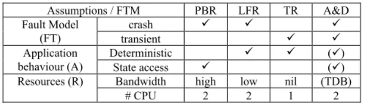
Assumptions / FTM PBR LFR TR A&D Fault Model (FT) crash transient Application behaviour (A) Deterministic () State access ()
Resources (R) Bandwidth high low nil (TDB)
# CPU 2 2 1 2
Fig. 1. Assumptions and fault tolerance design patterns charateristics The underlying characteristics of the considered FTMs, in terms of (FT,A,R), are shown in Fig. 1. For instance, PBR and LFR tolerate the same fault model, but have different A and R. PBR allows non-determinism of applications because only the Primary computes client requests while LFR only works for deterministic applications as both replicas compute all requests. LFR could tackle non-determinism if the application was not considered a black-box, as in our approach. PBR requires state access for checkpoints and higher network bandwidth (in general), while LFR does not require state access but generally incurs higher CPU costs (and, consequently, higher energy consumption) as both replicas perform all computations.
During the service life of the system, the values of the parameters enumerated in Fig. 1 can change. An application can become non-deterministic because a new version is installed. The fault model can become more complex, e.g., from crash-only it can become crash and value fault due to hardware aging or physical perturbations. Available resources can also vary, e.g., bandwidth drop or constraints in energy consumption. For instance, the PBR→LFR transition is triggered by a change in application characteristics (e.g. inability to access application state) or in resources (bandwidth drop), while the PBR→A&D transition is triggered by a change in the considered fault model (e.g. safety property verification). Transitions can occur in both directions, according to parameter variation.
The priority is the fault model, the selection of the solution (i.e. the composition of several FTMs) depending on the application characteristics and the available resources. The final objective is always to comply with the dependability properties during the service lifetime.
D. Design for adaptation of FTMs
Our “design for adaptation” aims at producing reusable elementary components that can be combined to implement a given fault tolerance or safety mechanism. Any FTM follows the generic Before-Proceed-After metamodel. Many FTMs can be mapped and combined using this model, as shown in Fig. 2.
FTM Before Proceed After
PBR (primary)
PBR(backup) Compute Checkpointing State update LFR (leader)
LFR (follower)
Forward request Compute Notify Handle request Compute Handle notification TR Save/restore state Compute Compare
A&D Compute Assert
Fig. 2. Generic execution scheme for FT design patterns
Composition implies nesting the Before-Proceed-After metamodel. This approach improves flexibility, reusability, composability and reduces development time. Updates are minimized since just few components have to be changed.
E. Runtime support
The software runtime support must provide key features to manipulation the component graph. Any application or an FTM is perceived as a graph of components. From previous experiments reported in [17], the following primitive are required.
• Dynamic creation, deletion of components; • Suspension, activation of components;
• Control over interactions between components for the creation and the removal of connections (bindings);
Our first implementation was done on a reflective component-based middleware, FRASCATI [14] providing a scripting language to manipulate the component graph, FScript [15]. The proposed approach is reproducible on any other support that provides these features.
IV. ADAPTIVE FAULT TOLERANCE ON ROS
The main goal of ROS is to allow the design of modular applications: a ROS application is a collection of programs, called nodes, interacting only through message passing. Developing an application involve the assembly of nodes, which is akin to component-based approaches. Such an assembly is referred to as the computation graph of the application.
A. Component model and reconfiguration
Two communication models are available in ROS: a pub- lisher/subscriber model and a client/server one. The pub- lisher/subscriber model defines one-way, many-to-many, asyn- chronous communications through the concept of topic. When a node publishes a message on a topic, it is delivered to every nodes subscribing to this topic. Note that a publisher is not aware of the subscriber to its topic nor the other publishers. The client/server model defines bidirectional transaction (one request/one reply) synchronous communications through the concept of service. A node providing a service is not aware of the client nodes that may use its service. These high-level communication models allows to add, replace or delete nodes in a transparent manner, either offline or online.
To provide this level of abstraction, each ROS application includes a special node called the ROS Master. It provides registration and lookup services to the other nodes. All nodes register services and topics to the ROS master. It is the only node that has a comprehensive view of the computation graph. When a node issues a service call, it queries the master for the address of the node providing the service and then it sends its request to this address.
In order to be able to add fault-tolerance mechanisms to an existing ROS application in the most transparent manner, we need to implement interceptors. An interceptor provides a means to insert functionality, such as safety or monitoring nodes, into the invocation path between two ROS nodes. To this end, a relevant ROS feature is its remapping capability. At launch time, it is possible to reconfigure the name of any services or topics used by a node. Thus, requests and replies between nodes can be rerouted to interceptor nodes.
B. Implementing a componentized FT design pattern
A full implementation on ROS of a duplex FT design pattern, a Primary Backup Replication (PBR) combined with a
Time-Redundancy (TR) design pattern is developed here. 1) Generic Computation Graph
We have identified a generic pattern for the computation graph of a FTM. Figure 3 shows its application in the context of ROS. Node Client uses a service provided by Server. The FTM computation graph is inserted between the two thanks to the ROS remapping feature. Since Client and Server must be re-launched for the remapping to take effect, the insertion is done offline. The FTM nodes, topics, and services are generic for every FTM discussed in section II. Implementing a FTM consist in specializing the before, proceed, and after nodes with its corresponding behavior (see Fig. 3).
Fig. 3. Generic computation graph for FTM
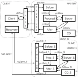
We illustrate the approach, through a Primary-Backup Replication (PBR) mechanism added to the Client/Server application in order to tolerate a crash fault of the Server. Fig. 4 presents the associated architecture. Three machines are involved: the Client, which is also hosting the ROS, master, the
MASTER site hosting the primary replica and the SLAVE site hosting the backup replica. For the sake of clarity, the symmetric topics and services between MASTER and SLAVE are not represented. Elements of the slave are suffixed with “_S”.
2) Implementing PBR
We present the behavior of each node, the topics/services used through a request/reply exchange between a node Client and node Server (see Fig. 4).
• Client sends a request to Proxy (service clt2pxy);
• Proxy adds an identifier to the request and transfers it to
Protocol (topics pxy2pro);
• Protocol checks whether it is a duplicate request: if so, it sends directly the stored reply to Proxy (topics pro2pxy). Otherwise, it sends the request to Before (service pro2bfr); • Before transfers the request for processing to Proceed
(topics bfr2prd); no action is associated in the PBR case, but for other duplex protocol, Before may synchronize with the other replicas;
• Proceed calls the actual service provided by Server (service
prd2srv) and forwards the result to After (topics prd2aft);
• After gets the last result from Proceed, captures Server state by calling the state management service provided by the
server (service aft2srv), and builds a checkpoint based on this information which it sends to node After_S of the other replica (topics aft2aft_S);
• Protocol gets the result (topics aft2pro) and sends it to
Proxy (topics pro2pxy);
•
On the backup replica, After_S transfers the last result to its protocol node Proto_S (topics aft2pr_S) and sets the state of its server to match the primary.In parallel with request processing, the node crash detector on the MASTER (noted CD) periodically gives a proof of life to the crash detector (CD_S) on the SLAVE to assert its liveliness (topics CD2CD_S). If a crash is detected, then the crash detector of the slave notifies the recovery node (topics
CD_S2rcy). This node has two purposes: (i) in order to enforce
the fail-silent assumption, it must ensure that every node of the
MASTER are removed; (ii) it switches the binding between the
Client proxy and the MASTER protocol to the SLAVE protocol. Thus, the SLAVE will receive the Client’s requests and will act as the Primary, changing its operating mode.
Fig. 4. Computation graph of a PBR mechanism
ROS does not provide APIs to dynamically change bindings between nodes. The node developer must implement the transition logics. The SLAVE protocol spins waiting for a notification from recovery (topics rcy2pro_S). This is done using the ROS API: background threads, within a node, check for messages independently of the node’s main functionality. Upon reception of this topic, protocol subscribes to topic
pxy2pro and publishes to topic pro2pxy. After this transition,
the proxy forwards the Client’s requests to the Slave protocol.
3) Impact on the existing application
From the designer viewpoint, there are two changes
required to integrate a FTM computation graph to its application. First, Client will have to be remapped offline to call the proxy node’s service instead of directly the Server. Second, state management services, to get and set the state of the node, must be integrated to the Server. Form an object-oriented viewpoint any server inherits from an abstract class
stateManager providing two virtual methods, getState and setState, overridden during the server development.
Adaptive Fault-Tolerance: from a Component-Based
Approach to ROS
Michael Shell
School of Electrical and Computer Engineering Georgia Institute of Technology
Atlanta, Georgia 30332–0250 Email: http://www.michaelshell.org/contact.html
Homer Simpson
Twentieth Century Fox Springfield, USA Email: [email protected]
James Kirk and Montgomery Scott
Starfleet Academy San Francisco, California 96678-2391
Telephone: (800) 555–1212 Fax: (888) 555–1212
Abstract—The abstract goes here.
I. ADAPTATIVEFAULTTOLERANCE ONROS A. Introduction to ROS
ROS can be viewed as a middleware running on top of a Unix-based operating system (typically Linux). The main goal of ROS is to allow the design of modular applications : a ROS application is a collection of programs, called nodes, interacting only through message passing. Developing an ap-plication involve the assembly of nodes, which is akin to component-based approaches. Such an assembly is referred to as the computation graph of the application.
B. Component model and reconfiguration
Two communication models are available in ROS: a lisher/subscriber model and a client/server one. The pub-lisher/subscriber model defines one-way, many-to-many, asyn-chronous communications through the concept of topic. When a node publishes a message on a topic, it is delivered to every nodes subscribing to this topic. Note that a publisher is not aware of the subscriber to its topic nor the other publishers. The client/server model defines bidirectional transaction (one request/one reply) synchronous communications through the concept of service. A node providing a service is not aware of the client nodes that may use its service. These high-level communication models allows to add, replace or delete nodes in a transparent manner, either offline or online.
To provide this level of abstraction, each ROS application includes a special node called the ROS Master. It provides registration and lookup services to the other nodes. All nodes register there services and topics to the ROS master. It is the only node which has a comprehensive view of the computation graph. When a node issues a service call, it queries the master for the address of the node providing the service and then it sends its request to this address.
In order to be able to add fault-tolerance mechanisms to an existing ROS application in the most transparent manner, we need to implement interceptors. An interceptor provides a means to insert functionality, such as safety or monitoring nodes, into the invocation path between two ROS nodes. To this end, a relevant ROS feature is its remapping capability. At launch time, it is possible to reconfigure the name of any
Client P r o x y P r o t o c o l Before Proceed After Server FTM clt2pxy prd2srv pro2bfr aft2pro prd2aft bfr2prd pxy2pro pro2pxy service topic
Fig. 1. Generic computation graph for FTM
services or topics used by a node. Thus, requests and replies between nodes can be rerouted easily to interceptor nodes. C. Implementing a componentized FT design pattern
1) Generic Computation Graph: We identified a generic pattern for the computation graph of a FTM. Figure 1 shows its application in the context of ROS. Node Client uses a service provided by Server. The FTM computation graph is inserted between the two thanks to the ROS remapping feature. The FTM nodes, topics, and services are generic for every FTM discussed in section II. Implementing a FTM consist in specializing the before, proceed, and after nodes with its corresponding behavior (see table X).
We illustrate the approach, through a Primary-Backup Replication (PBR) mechanism added to the Client/Server application in order to tolerate a crash fault of the Server. Figure 2 shows the architecture. Three machines are involved : the CLIENT which is also hosting the ROS master, the MASTER hosting the primary replica and the SLAVE hosting the backup replica. For the sake of clarity, the symmetric topics and services between MASTER and SLAVE are not represented. Elements of the slave are suffixed with ” S”
We present the behavior of each nodes, the topics/services used through a request/reply exchange between a node Client and node Server.
6 Fig. 5. Composition principle of FT mechanisms (PBR+TR).
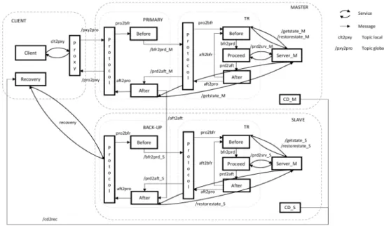
C. Composition of FT mechanisms
The generic computation graph for FTM is designed for composability. In this section, the composition scenario is two-fold. We first illustrate the composition of two FTMs, PBR for crash faults and TR for transient value faults. Initially the application was installed with PBR. From an operational standpoint, at a given point in time, transient faults impacting numerical calculations appeared due to hardware components aging or sudden increase of environmental radiations. In a second step, later on, we consider that the communication channel between client and server can be the target for intrusions. Cryptographic protocols, based for instance on a simple Public Key Infrastructure (PKI), can be used to cipher communications and add cryptographic signatures.
Fig. 6. Composition principle of FT mechanisms.
1) Composition of PBR and TR on ROS
With respect to request processing, a Protocol node and a Proceed node present the same interfaces: a request as input, a reply as output. Hence, a way to compose mechanisms is to replace the Proceed node of a mechanism by a Protocol and its associated Before/Proceed/After nodes, as shown in Fig. 6. Our approach enables developing a new mechanism on the foundation of several existing ones. This improves the development time and the assurance in the overall system,
since all mechanisms have been validated off-line by test and fault injection techniques.
The architecture of the composite FTM made of PBR and TR is given in Fig. 5. This figure is an extension of Fig. 4 where the Proceed node of the PBR has been replaced with the
Protocol node of the TR implementation.
2) Composing FTM with Cryptographic protocols
The generic computation graph presented in Fig. 3 enables cryptographic protocols to be seamlessly added to an application, already equipped with accidental fault tolerance mechanisms, PBR and TR in our example. The cryptographic mechanism (called SEC for security) is located at both the client (SEC_C) and the server side (SEC_S) as shown in Fig. 7). On the server side, SEC operates before PBR and TR.
Fig. 7. Composition principle of SEC with other FT mechanisms.
In this example, we only deal with possible intrusions between the client and the server.
We assume that a node implements the Certification
Authority (CA). Three topics are used to communicate with the
CA, namely Cli2CA for the Client, Master2CA for the Master and Slave2CA for the Slave. The topic Cli2CA enables the
Before node of the Client to collect the certificate of the Server.
Similarly, the topic Master2CA and Slave2CA enable Before of
Client P r o x y P r o t o c o l Before Proceed After Server clt2pxy prd2srv pro2bfr aft2pro prd2aft bfr2prd pxy2pro pro2pxy aft2srv P r o t o _ S Before_S Proc_S After_S Server_S prd2srv_S pro2bfr_S aft2pro_S prd2aft_S bfr2prd_S aft2srv_S MASTER SLAVE CLIENT aft2aft_S Recovery CD CD_S CD_S2rcy CD2CD_S rcy2pro_S
Fig. 2. Computation graph of a PBR mechanism
• Proxy adds an identifier to the request and transfer it to Protocol (topic pxy2pro);
• Protocol checks whether it is a duplicate request: if so, it sends directly the stored reply to Proxy (topic pro2pxy), otherwise, it sends the request to Before (service pro2bfr);
• Before transfer the request for processing to Proceed (topic bfr2prd); no action in the PBR case, for other duplex protocol, Before may synchronize with the other replica;
• Proceed calls the actual service provided by Server (service prd2srv) and forwards the result to After (topic prd2aft);
• After gets the last result form Proceed and captures Server state by calling the state management service provided by the server (service aft2srv) and builds a checkpoint based on this information which it sends to node After S of the other replica (topic aft2aft S); • Protocol gets the result (topic aft2pro) and sends it to
Proxy (topic pro2pxy);
• on the other replica, After S transfers the last result to its protocol node proto S (topic aft2pro S) and set the state of its server to match the primary.
Client P r o x y P r o t o c o l Before After FTM1 P r o t o c o l Before After Proceed FTM2 Server
Fig. 3. Composition of FTM mechanisms
between the Client proxy and the Master protocol to the Slave protocol. Thus, the Slave will receive the Client’s requests and will act as the Primary, changing its operating mode.
Note that ROS does not provide APIs to dynamically change bindings between nodes. The transition logic must be implemented by the developper in the nodes. For instance, the Slave protocol spins waiting for a notification from recovery (topic rcy2pro S). This is carried out by background threads within a node independently of its main functionality. We use some ROS API for this. Upon reception of this topic, protocol advertise that it is providing service 2 (as defined in figure X). Further request from the Client will now be forwarded by the proxy to the Slave protocol becoming now primary.
2) Impact on the existing application: Form the application designer point of view, there are two main changes required to integrate a FTM computation graph to its application. First, Client will have to be remapped to call the proxy nodes service instead of directly the service of Server. Second, state management services, to get and set the state of the node, must be integrated to the Server. Form an Object Oriented viewpoint any server inherit from an abstract class stateManager provid-ing two virtual methods, getState and setState. Both methods are overridden during the server development.
D. Composition of mechanisms
The generic computation graph for FTM is designed for composability. With respect to request processing a Protocol node and a Proceed node present the same interfaces: a request as input, a reply as output. Hence, a way to compose mechanisms is to replace the proceed node of a mechanism by a protocol and its associated before/proceed/after nodes. Figure 3
E. Dynamic Adaptation of FTM
A set of minimal API required for dynamic adaptation of FTMs have been established in previous research [Miruna]:
• control over components life cycle at runtime (add,
C P r o x y P r o t o c o l B A P r o t o c o l B A P PBR S P r o t o c o l B A P r o t o c o l B A SEC_S TR SEC_C
the Master, respectively the Slave, to collect the certificate of the Client. We assume that all parties know CA's public key. We assume that, for each participant, Client or Server, Before and After of the SEC mechanism share the pair of private and public keys they received when initialized.
Before of the Client can then ciphers the request with !!"#! ,
the Server's public key, and adds a signature, using !!"#$! the
Client's private key;
Using the generic scheme given in Fig. 6, a message is sent by the client to the server side through a new topic (called
Client_2_Server) connecting Before of SEC_C to Protocol of
SEC_S.
Before of the Master deciphers the request with !!"#$! , the
Server's private key, and checks the signature, using !!"#! , the
Client's public key;
The Server can then proceed with a valid deciphered request through PBR and TR.
Conversely, After of the Master ciphers the reply and computes a signature. After of the Client deciphers the reply, checks the signature, and finally delivers the reply to the
Client.
The communication between Master and Slave can also be secured using a similar security protocol.
V. DYNAMIC COMPOSITION: TO WHAT EXTENT WITH ROS
A. Dynamic Adaptation of FTM
Dynamic adaptation of FTM is required to provide continuity of service in resilient systems. The question is then: is it possible to safely adapt a FTM at runtime in the context of ROS? A set of minimal API required to guarantee the consistency of the transition between two different FTMs has been established in previous work [14]:
• Control over components life cycle at runtime (add, remove, start, stop).
• Control over interactions between components at runtime, for creating or removing bindings.
Furthermore, ensuring consistency before, during and after reconfiguration, requires that no requests or replies are lost: • Components are stopped in a quiescent state, i.e. when all
internal processing has finished
• Incoming requests on stopped components must be buffered
With the exception of add and remove, ROS does not provide these APIs. However, these APIs can be emulated with dedicated logics in some nodes. For instance, we are using some binding control in the Primary to Backup switch described in our example. Controlling node lifecycle is more complex but can be done in the same manner and these principles can be applied in the context of dynamic adaptation, i.e. add new nodes at runtime and binding them in the computation graph.
The protocol node plays a central part to provide proper consistency during a transition. Indeed, our design pattern for FTM is such that only stateless nodes, namely before, proceed and after, need to change in order to switch from one FTM to the next. Thus, protocol does not need to be changed during a transition and it can be used to buffer messages and detect when the changing nodes are in quiescent state. To do this,
protocol is extended to deal with three new messages. The first
one is used to signal protocol that a transition is about to happen and it has to start storing incoming requests. The second one is published by protocol and confirms that the FTM is in a safe state and transition can be safely executed. In particular, the safe state is reached when protocol has received the replies of all pending requests. The third message is used to signal protocol that the transition has been executed and it can resume normal operation and release the requests stored during the transition.
Note that the described transition technique requires that an FTM is already in place in the system, meaning that the Client and the Server are already configured to use our proxy nodes. Installing an FTM in an application without interruption is not possible with ROS since control over binding at runtime is only possible with dedicated code within the nodes.
B. Implementing Dynamic Binding on ROS
Dynamic binding is not a core feature of ROS. As far as AFT is concerned, this is a major concept for runtime adaptation. However, ROS does not contain any API to control bindings online. In ROS, connections between nodes are based on pre-defined Topics and messages are sent/received through ports.
A Topic is defined by:
• A name: ports are connected through a named Topic. • A sending port: Publisher or Client sends messages. • A receiving port: Subscriber or Server receives messages. • A data type: a Topic is assigned a data type for messages.
Several Publishers and Subscribers can communicate on the same Topic according to a unique message format, a given data type. The connection of a new node to the system implies creating a new Topic with its own data type. Suppose that
Node A and B are connected to a Node C. When the data type
from A to C and B to C is different, then two Topics are needed. If the same data type is used, then just one Topic is needed.
We defined two types of dynamic bindings: a) dynamic binding on Pre-Defined Topics (PDT); b) dynamic binding on
UnAnticipated Topics (UAT).
Some topics can be pre-defined, for instance two topics, one between the Client and the primary, one between the Client and the backup in a PBR replication strategy. Others topics are unanticipated: some new topics are needed when a new node is created with a new data type for messages. This might be needed for the on-line composition of FTM later during the lifetime of the system.
Dynamic binding on PDT: This is the simpler case since Topics preexist in the ROS configuration. For example, in the
PBR replication strategy, the two Protocols nodes (in the two replicas) are bound to the same topic, but the Slave’s port is deactivated. The Proxy sends the request but only one
Protocol node receives it.
A third Node, in our implementation the Recovery node, is used to activate the Slave’s port when the Master crashes. A dedicated topic is defined and used to this aim. After recovery, the former Slave, i.e. new Master, can now listen to the Proxy and receive messages. It is the simplest way to dynamically bind Nodes since the same data type is used in this case.
Dynamic binding on UAT: In the case of unanticipated topics,
the binding is a bit more difficult to achieve. Instead of reactivating a port, two communication ports must be created. Suppose that two nodes A and B must be connected at a given point in time through a new topic. The solution is based on: • two methods added to both A and B to create ports, one for
the publisher, one for the subscriber;
• a third node used to trigger and control the creation of the channel (activation of the methods).
The Topic defined offline corresponds to one data type that is handled by the methods. The third Node is part of the implementation of AFT, in fact part of the implementation of an adaptation engine responsible for the manipulation the FTM configuration.
VI. LESSONS LEARNT AND CONCLUSION
Installing an FTM within a ROS application or adapting an existing FTM does not incur technical difficulties as long as the system’s nodes (application + FTM) can be stopped and re-launched. Indeed, using the remapping capability of ROS implies rewriting some configuration files, which are taken into account only during the initialization of the nodes. For system where interruption of service is not an option, adaptation has to be done at runtime. In the context of ROS, this requires some additional software development.
Regarding the features of ROS for implementing AFT, we can say that they are not fully satisfactory. The main troubles relate to the dynamic binding on unanticipated topics and on the weak API to control components at runtime. However, ROS provides separation of concerns, since component can be mapped to nodes (Unix processes) that have their own address space. Dynamic binding is possible on pre-defined topics. For unanticipated topics, a customized solution was proposed in this work. Control over components relies on the underlying operating system to suspend and activate nodes, i.e. processes and threads, and to store input messages. However, ROS is an acceptable candidate for AFT, in other words, resilient computing using AFT can be implemented on ROS.
Regarding safety issues, the design of AFT and its validation is always carried out off-line. Any composition of mechanisms due to a change in the various axis of the change model denoted (FT, A, R) follows a design and validation process off-line that can be conformant to standards like DO178C or ISO26262, to comply with certification if needed.
Some performance measurements have been obtained. The overhead of the FTM (composition of PBR+TR) is less than 10 ms (on a PC, Intel I7 Quad Core, 8 Go RAM). Actually, the real overhead is very dependent of the complexity of the application, in particular the handling of the application state, and the network performance. As a conclusion, the implementation of AFT on ROS is independent from the application and the network.
REFERENCES
[1] J.-C. Laprie, “From Dependability to Resilience,” in 38th IEEE/IFIP International Conference on Dependable Systems and Networks (DSN), 2008.
[2] K. H. K. Kim and T. F. Lawrence, “Adaptive Fault Tolerance: Issues and Approaches,” in Proceedings of the Second IEEE Workshop on Future Trends of Distributed Computing Systems. IEEE, 1990, pp. 38– 46.
[3] C. Krishna and I. Koren, “Adaptive Fault-Tolerance for Cyber- Physical Systems,” in IEEE International Conference on Computing, Networking and Communications (ICNC), 2013, pp. 310–314.
[4] J. Fraga, F. Siqueira, and F. Favarim, “An Adaptive Fault- Tolerant Component Model,” in 9th Workshop on Object- Oriented Real-Time Dependable Systems. IEEE, 2003, pp. 179–186.
[5] L. C. Lung, F. Favarim, G. T. Santos, and M. Correia, “An Infrastructure for Adaptive Fault Tolerance on FT-CORBA,” in 9th International Symposium on Object and Component- Oriented Real-Time Distributed Computing. IEEE, 2006.
[6] O. Marin, P. Sens, J.-P. Briot, and Z. Guessoum, “Towards Adaptive Fault-Tolerance for Distributed Multi-Agent Sys- tems,” in 4th European Research Seminar on Advances in Distributed Systems, 2001, pp. 195–201.
[7] J.HighsmithandA.Cockburn,“AgileSoftwareDevelopment: The Business of Innovation,” Computer, vol. 34, no. 9, pp. 120–127, 2001.
[8] P. McKinley, S. Sadjadi, E. Kasten, and B. H. C. Cheng, “Composing Adaptive Software,” Computer, vol. 37, no. 7, pp. 56–64, 2004. [9] [11] C. Szyperski, Component Software: Beyond Object-Oriented
Programming, 2nd ed. Boston, MA, USA: Addison-Wesley Longman
Publishing Co., Inc., 2002.
[10] [12] J. Marino and M. Rowley, Understanding SCA (Service Com-
ponent Architecture). Addison-Wesley Professional, 2009.
[11] [13] G. Kiczales, J. Lamping, A. Mendhekar, C. Maeda, C. Lopes, J.-M. Loingtier, and J. Irwin, “Aspect-oriented program- ming,”
ECOOP’97Object-Oriented Programming, pp. 220– 242, 1997.
[12] H. Martorell, J.-C. Fabre, M. Lauer, M. Roy and R. Valentin. Partial Updates of AUTOSAR Embedded Applications — To What Extent?, in European Dependable Computing Conference (EDCC), 2015, Paris, France.
[13] M.Stoicescu, J.-C. Fabre, M. Roy, From Design for Adaptation to Component-Based Resilient Computing. PRDC 2012: 1-10
[14] L. Seinturier, P. Merle, R. Rouvoy, D. Romero, V. Schi- avoni, and J.-B. Stefani, “A Component-Based Middleware Platform for Reconfigurable Service-Oriented Architectures,” Software: Practice and Experience, 2011.
[15] M. Leger, T. Ledoux, and T. Coupaye, “Reliable Dynamic Reconfigurations in a Reflective Component Model,” 13th International
Conference on Component-Based Software En- gineering, 2010.
[16] D. Powell, "Failure Mode Assumption and Assumpion Coverage", in Proc. of the IEEE Int. Symp. on Fault-Tolerant Computing (FTCS-22), Boston (USA), 1992, pp.386-395. (revised in the book Predictably Dependable Computing Systems, ISBN 3-540-59334, 1995.)
[17] M.Stoicescu, "Architecting Resilient Computing Systems: A Component-based Approach", PhD thesis, National Polytechnic Institute of Toulouse (INP), 2013. ww.theses.fr/en/2013INPT0120.