Publisher’s version / Version de l'éditeur:
Vous avez des questions? Nous pouvons vous aider. Pour communiquer directement avec un auteur, consultez la
première page de la revue dans laquelle son article a été publié afin de trouver ses coordonnées. Si vous n’arrivez pas à les repérer, communiquez avec nous à [email protected].
Questions? Contact the NRC Publications Archive team at
[email protected]. If you wish to email the authors directly, please see the first page of the publication for their contact information.
https://publications-cnrc.canada.ca/fra/droits
L’accès à ce site Web et l’utilisation de son contenu sont assujettis aux conditions présentées dans le site LISEZ CES CONDITIONS ATTENTIVEMENT AVANT D’UTILISER CE SITE WEB.
Proceeding of the 6th Conference on Optical 3-D Measurement Techniques, 2003
READ THESE TERMS AND CONDITIONS CAREFULLY BEFORE USING THIS WEBSITE.
https://nrc-publications.canada.ca/eng/copyright
NRC Publications Archive Record / Notice des Archives des publications du CNRC : https://nrc-publications.canada.ca/eng/view/object/?id=1d966a5e-7855-487f-920f-28d9dbc7a4fb https://publications-cnrc.canada.ca/fra/voir/objet/?id=1d966a5e-7855-487f-920f-28d9dbc7a4fb
NRC Publications Archive
Archives des publications du CNRC
This publication could be one of several versions: author’s original, accepted manuscript or the publisher’s version. / La version de cette publication peut être l’une des suivantes : la version prépublication de l’auteur, la version acceptée du manuscrit ou la version de l’éditeur.
Access and use of this website and the material on it are subject to the Terms and Conditions set forth at
New Development in 3D Laser Scanners: From Static to Dynamic
Multi-Modal Systems
Information Technology de l'information
New Development in 3D Laser Scanners:
From Static to Dynamic Multi-Modal Systems *
Blais, F., Beraldin, J.-A., El-Hakim, S., Godin, G.
September 2003
* published in the Proceeding of the 6th
Conference on Optical 3-D Measurement Techniques. Zurich, Switzerland. September 22-25, 2003. NRC 45884.
Copyright 2003 by
National Research Council of Canada
Permission is granted to quote short excerpts and to reproduce figures and tables from this report, provided that the source of such material is fully acknowledged.
Blais & al.
1 1
NEW DEVELOPMENTS IN 3D LASER SCANNERS: FROM
STATIC TO DYNAMIC MULTI-MODAL SYSTEMS
*Francois Blais, J.-Angelo Beraldin, Sabry El-Hakim, Guy Godin
National Research Council Canada [email protected]
KEY WORDS: Range sensor, 3D models, laser scanner, color, hand-held, texture mapping.
ABSTRACT
This paper reviews some of the most popular 3D laser scanning methods available today and describes recent research done in the field of multi-modal 3D laser systems, including 3D color laser, perspective color projection on complex 3D surfaces, some hand-held techniques, and introduces our most recent work to create a high-resolution (sub-millimeters) medium volume (m3) truly hand-held system.
1 INTRODUCTION
From the early and rudimentary 3D laser scanner prototypes of the early 80s and the specialized applications of the 90s, research and development of 3D surface digitizers have seen tremendous progress, especially during the last decade. Commercial 3D sensors are becoming more friendly and attractive to users, complemented by powerful algorithms and data processing software. Cost is still high, mostly because of the small market and engineering costs but also because of the expensive supporting equipment that accompanies a 3D scanner optical head: complex mechanical infrastructures, positioning equipment and motor stages, computers, tripods, calibration infrastructure, and not to underestimate the embedded and third party processing software that often accounts for more than half the cost.
Nowadays, from a research perspective, the classical 3D laser scanner that only produces range or volumetric data of static objects does not satisfy many of today and surely future applications. Ranging systems must work accurately under dynamically varying natural environments. They must also automatically produce accurate and precise reflectance information. Color texture using RGB lasers, collinear color cameras, and perspective projection methods (texture mapping) have been successfully demonstrated in the labs and some of these techniques are currently being commercialized. Multi-modal ranging techniques that combine photogrammetry,
*
NRC-45884
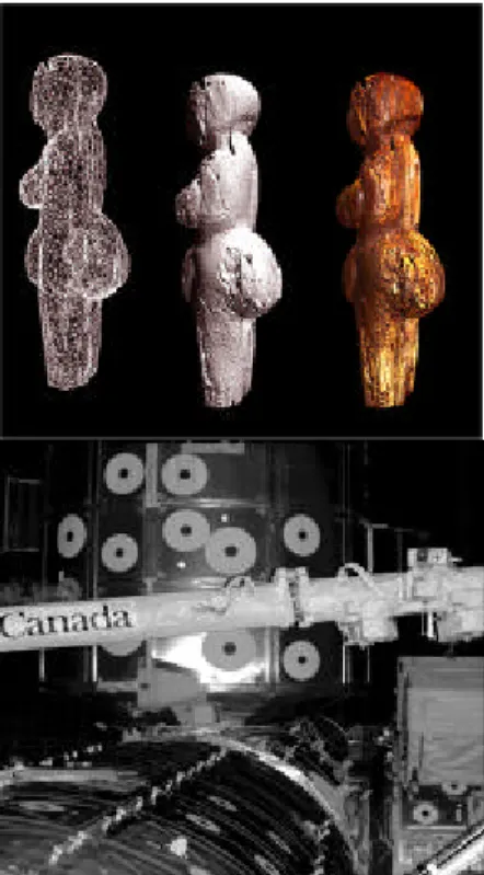
Figure 1: Applications of 3D
range from high accuracy color models of historical objects using RGB lasers, to large structures in the harsh environment of space.
active triangulation, time-of-flight, and high-resolution color texture information, are the subject of intensive research. Very important is the development of portable hand-held systems that will remove many of the constraints imposed by costly mechanical infrastructures. Registration and other powerful processing software that automatically combines data from different modalities are now being integrated, often transparently, within range sensing systems.
A quick review of the different 3D methods is presented in section 2 to illustrate the advantages and disadvantages of the most popular methods from an optical point of view. This will serve as a basis for the other sections. Section 3 discusses a few color texture projection systems and methods. Section 4 will introduce hand-held systems including configurations based on external positioning devices such as magnetic and optical trackers, and what we call the “truly” hand-held systems that do not require any external positioning. The paper concludes with the most up-to-date research done at NRC in the field of dynamic ranging and hand-held acquisition, to create accurate 3D models of freely moving objects with respect to the laser scanner. By combining all these methods, it will be possible in a near future to create highly accurate and realistic virtualized copies of real objects, at an acceptable cost. Acquiring a 3D image will be like acquiring a 2D image with a digital camera.
2 BASIC RANGE SENSING: A QUICK REVIEW
Various methods for acquiring range images were originally surveyed by (Jarvis, 1983) and (Besl, 1988). Other surveys were later presented by (Tiziani, 1997) and by (Chen, 2000). More recently, (Blais, 2003a) presented a comprehensive review of the different range sensing techniques from an industry-oriented perspective. Here we limit the discussion showing only the advantages and concerns of the most popular 3D ranging methods in terms of the optical properties of a method and their impacts on applications.
2.1 Slit scanner
The slit scanner is by far the most widely used triangulation-based 3D laser camera because of its lower cost. It uses an inexpensive laser diode to project a laser line and a low cost CCD or CMOS camera to detect a complete profile of 3D points in a single video frame. Sweeping the laser profile over the object surface creates a complete 3D model. Because of its low cost, the number of slit scanners available commercially is very large and a list is available in (Blais, 2003a). Their main disadvantage however lies with the compromise between field of view and depth resolution that must be made. They also suffer from poor intensity dynamic range and limited immunity to ambient light compared to single point scanners. The mechanical infrastructures needed to sweep the laser profile or the need for external positioning devices significantly increase cost and complicate their use.
2.2 Pattern projection and Moiré
Pattern techniques use multiple stripes of light or patterns projected on the object rather than a single laser line. Several methods have been proposed: Moiré uses either precisely matched pair of gratings; a projective patterns such as binary coded pattern (e.g. Gray codes), or phase-shifted fringes patterns (Blais, 2003a). Coded pattern methods are popular because of the availability of projectors and because a full 3D volume can be acquired in just a few video frames, making these methods interesting candidates for hand-held systems. The use of incoherent light also reduces speckle noise associated with laser and consequently provides nice surface smoothness. A major disadvantage however is the very small depth of field when compared to laser stripe scanners and single point scanners, thus limiting their use to relatively flat objects. Additional technical issues,
Blais & al.
3 3
such as smaller depth of focus and defocus of the projected pattern, reduced dynamic range in intensity, and costs are important practical limitations that are either technically difficult to overcome, or simply impossible according to the laws of physics.
2.3 Single point triangulation laser scanners
Single point 3D laser scanners offer several technical advantages. The whole CCD length can be optimized for a given volume of measurement resulting in higher resolution and accuracy than slit scanners, for example. Laser power and signal control can be optimized on a per-voxel basis allowing large dynamic range, a must for metallic and reflective surfaces. Cost of the optical head is higher than slit scanners because of the use of mechanical scanning galvanometers and specialized components such as linear CCDs. In practice however, higher cost is the result of the needs for better quality components to provide the extra performances obtainable with these methods. When compared with equivalent high accuracy slit scanners, TOF units, or pattern projection systems, the final cost of a complete system, not just the optical head, is comparable.
2.4 Time-of-flight systems
For large structures, time-of-flight 3D scanners (TOF) are by far the preferred choice for measurements at long range. Range accuracy is relatively constant for the whole volume. TOF systems measure the round trip delay of light propagating through air. The accuracy of a TOF laser scanner is basically limited by how well the electronics can resolve time. Different methods have been proposed, pulse, amplitude modulation, frequency modulation, hybrid detection, and self-mixing diodes (Blais, 2003a). The cost of a TOF system is directly proportional to its accuracy. Pulse methods offer the less expensive alternative with accuracies in the 1 cm range, AM modulation offers mm accuracies for shorter volumes. FM modulation systems are by far the most accurate with accuracies in the fraction of a millimeter but at high costs, explained by the needs for extremely accurate mechanical rotation stages (e.g. ceramic ball bearings) and temperature control devices. These scanners are usually bulkier because of components size and the need to provide a larger thermal mass for better temperature control of the device.
2.5 Compromise range accuracy vs. volume and field of view
Range sensors are primarily optical devices and as such will be limited by the same laws of physics as any optical system. The myth that accuracy and resolution are directly related to the number of pixels in the image must be disputed; a nice image is not necessarily accurate. This section explains the basic equations needed to evaluate a given 3D principle.
From the sine law range and field of view of any triangulation based laser scanner, including the slit scanner and the pattern projection systems, can be approximated by:
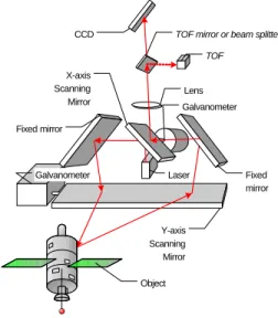
) tan(θ ⋅ + ⋅ = f p f d z ⋅ ⋅ = Φ − f Px 2 tan 2 1 (1) Y-axis Scanning Mirror CCD TOF Lens Fixed mirror Fixed mirror X-axis Scanning Mirror Galvanometer Galvanometer Object Laser
TOF mirror or beam splitter
Figure 2: Single point laser scanning
principle using synchronization and combining triangulation and TOF.
where f is the focal length of the lens, d is the triangulation base, and p is the position of the image on the detector of effective dimension Px. The accuracy (magnification) of a triangulation based 3D system, the field-of-view, and depth of field of the scanner are optical compromises given by
2 3
z
d
f
z
p
M
D=
=
⋅
δ
δ
( )
2 tan 2 2 3 Φ ⋅ ⋅ ⋅ = z Px d M D d f Pz z zmin = max + ⋅ 1 1 (2)where δp is the peak/pixel position accuracy, limited by sub-pixel speckle noise with lasers, or by the Rayleigh criterion in the case of pattern projection systems (Blais,2003a). To increase the accuracy of the sensor while preserving the field of view of the scanner Φ, we must either increase the triangulation base d, the dimensions of the detector Px, or reduce the range z. Increasing the dimension Px of the detector usually means more pixels and therefore a slower and more expensive detector. Increasing the triangulation base will reduce the depth of field zmax-zmin. and will increase
the bulk of the scanner.
These triangulation principles also apply to pattern projection methods with the important difference that the total depth of field of the sensor is comparatively smaller than a slit scanner for two main reasons: the detector is split to allow simultaneous measurements that will reduce the maximum dimension Pz, and the very poor depth of focus for the projector. Furthermore, assuming an aberration free projection and imaging system, image resolution will be further limited by the Rayleigh criterion.
With a single point probe, FOV and accuracy are independent. We can use a very long linear CCD that removes the constraints imposed by equation 2. Furthermore, triangulation based single point laser scanners and TOF systems are optically compatible and can be combined in a single head as shown in Figure 2. Because of the z2 behavior of triangulation, TOF is more accurate at ranges exceeding 10 m while triangulation is more accurate for range from 10 cm to 10 m.
3 MULTIPLE VIEWS AND COLOR TEXTURE RECONSTRUCTION
Due to the limits of the field of view of any scanner and the size and shape of most objects, multiple images must be acquired from different views to completely reconstruct an object. Two main solutions have been proposed: to use external global positioning equipment such as CMM, optical or mechanical trackers, inertial guidance systems, or to use software solutions to merge and stitch multiple images together.
The introduction of the Iterative Closest Point (ICP) registration algorithms or more generally the family of Iterative Corresponding Point methods (Rusinkiewicz, 2001) have greatly simplified the reconstruction of complex 3D models of objects using 3D scanners. Many variations of these algorithms have been published but basically the objective is to find the best rigid transformation matrix that maps one set of range data to a reference set. Furthermore, ICP methods when closely integrated with the laser scanner can provide a very good solution toward solving the more general problem of hand-held acquisition, as it will be shown in section 4.
The final step of color modeling and rendering of accurate 3D geometries is also essential to create realistic models of objects or environments. Color texture mapping can be divided into two main categories: image perspective techniques and reflectance modeling (Beraldin, 2002).
Image perspective methods are concerned with direct mapping of conventional color photographs onto a 3D model surface using perspective projection. The collinear color camera is the simplest form of perspective projection and several manufacturers already supply color texture in registration with range data (Blais, 2003a). Visual quality is still limited because of the low
Blais & al.
5 5
resolution video cameras used and the technical difficulties associated with the automatic calibration and registration of 2D images with range.
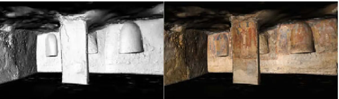
Combining range data and high-resolution color images acquired from different views and under different perspective transformation has been proposed by (El-Hakim, 2002), results are shown in Figure 3. The mapping method basically assigns the texture coordinates to each vertex of the 3D model using the collinearity equations that describe the view orientation of the 2D camera relative to the 3D object, for each independent view. One difficulty with perspective projection is the seamless integration of the different colors acquired from different views under different lighting conditions. The human eye is extremely sensitive to any unnatural discrepancy in the texture; luminosity must be perfectly adjusted. Another difficulty is related to inaccurate calibration and registration of the image with the model with the results that a given pixel could be projected on the wrong 3D surface. These effects are notorious on sharp discontinuities without accurate calibration (color pixels of a white forefront object projected on its darker background). The use of the intensity map created by the registered laser intensity has also been proposed by (Kurazume, 2001) to locally warp the 2D color texture image.
Reflectance modeling goes one step further than simply draping the texture on the surface. The objective is to extract from the measured color and shape the physical properties of the object that correspond to its color properties. This provides a very realistic color model of the object when rendered with artificial lighting on a computer screen. Perspective color techniques such as those described earlier mostly rely on the ambient illumination to provide color information, and even in the case of controlled illumination such as with external projectors, ambient light, specular, and reflections from different colored surfaces will seriously affect the color accuracy of the model.
One solution proposed is to add color to a single point laser scanner by coupling a polychromatic laser (RGB laser) to the optical fiber that brings the light source to the 3D camera. On the object, the laser light appears white. Color detection is implemented at the CCD by separating the primary colors using prisms. Because only the color information corresponding to the laser spot is
measured, the difficulties listed previously are eliminated. Figure 1 shows an example of perfectly registered color with 3D range data. The differences between Figure 3 and Figure 1 are subtle but nevertheless important. The disadvantage of this approach is that it requires scanning at very high resolution, even on flat surfaces, to cover all the colored details, thus making it less practical for large objects such as architecture.
Figure 3: Texture mapping results of a Byzantine Crypt by combining Laser Scanner Data (left) and
4 HAND-HELD SCANNER
4.1 The Constraint of Physical Rigidity during Acquisition
Mechanical stability is paramount in acquiring high definition 3D images. Any mechanical oscillation or vibration will seriously compromise the accuracy. Constraining the relative motion of the object, to be rigid and stable with respect to the laser scanner
system, is a major requirement that must be maintained during the acquisition of range data. To guarantee this stability, laser scanners are mounted on rigid and stable mechanical structures or tripods. Scanning motion is controlled by the use of accurate and usually expensive displacement stages. Table 1 shows typical acquisition times to create high-resolution 3D images assuming an acquisition rate of 10 kHz.
The use of external positioning devices such as optical trackers is
only a partial solution; absolute mechanical rigidity between the optical tracker and the object must still be maintained. Examples of such systems are the T-Scan from Steinbichler that uses a photogrammetry based optical tracker to compute the 6 degrees of freedom global position of the sensor head. Another example is the Polhemus FastSCAN, which is a hand-held slit scanner with magnetic trackers (Blais, 2003a).
4.2 Hand-held scanner
Figure 4 illustrates the hand-held experimentation we used to demonstrate true hand-held acquisition capabilities. The use of external positioning devices will obviously not work because of the lack of reference between the moving object and an external positioning devices that must in some way be attached to the object. Completely removing any constraint associated with rigidity or positioning devices will solve the problem of stability and can dramatically reduce the costs associated with mechanical structures.
The solution proposed by (Koninckx, 2003) uses a coded pattern projection method to freeze in a single video frame a relatively high-density 3D image of the object. ICP based methods are then used to stitch multiple images together. (Hébert, 2001) simultaneously projects a few profiles on the object and aligns the different profiles to recreate the object. (Popescu, 2003) aligns multiple views by
fitting rudimentary surfaces to the data and aligning the surfaces using color information.
The classical ICP algorithms generally assume that the data within one view are rigid, accurate, and most importantly stable during the acquisition (still images). The 3D scanning process must guarantee that the relative position between the scanner reference coordinate and the object under inspection is kept perfectly stable and distortion-free. One solution is therefore to acquire as many
Image Size (sec)
128 128 1.6 256 256 6.6 512 512 26.2 1024 1024 104.9
Table 1: Typical acquisition
speed using raster 3D imaging.
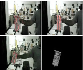
Figure 4: Tracking and imaging video sequence.
Top-left: the system searches for an object within the field of view of the scanner; top-right: the object is found and a very low-resolution distorted model is created; bottom-left: tracking is resumed and the model refined; bottom-right: results of tracking and model creation.
Blais & al.
7 7
3D points as possible in a single video frame. This reduces the possible candidates to pattern projection methods and consequently the accuracy and volume of measurement will suffer (see section 2). Furthermore, any small residual relative motion between the scanner and the object will introduce two undesired additional sources of errors: blur of the individual measurements, and overall motion-induced distortion across the scan.
Our interest is metrology and accurate documentation. The methods discussed earlier were mostly developed to create 3D models for
visualization purpose, thus accuracy was a secondary objective. In term of accuracy, synchronization principles remove the constraints imposed by equations 2 and provide the advantage of simultaneously having an accurate system, large FOV and high depth of measurement. Furthermore they are optically compatible with TOF systems, which means that a synchronized laser scanner system and a TOF unit can be combined in a single optical head, extending its range of utilization as illustrated in Figure 2.
From an initial set of sparse 3D points, the method we developed estimates a rough, partial, and potentially distorted model that provides a first approximation of the expected object true shape. This model is also used to track the position of the object in a 3D space therefore automatically limiting the acquisition to the object of interest and ensuring real time. New acquired profiles are added to this initial set to recursively improve and refine this initial model and to simultaneously provide object tracking information. Because motion is computed between two sets of profiles, motion-induced distortions within a profile are recursively compensated to sub-millimeter accuracy from the computed motion. At each iteration, a better estimate of the motion and position of the object relative to the camera is obtained. The final result is a high-resolution and accurate representation of free-moving objects (Blais, 2003b).
The model of the object is not known a priori. The system detects an object when it enters a specific volume (e.g. <2 m) within the field of view of the scanner and then locks on its overall
Figure 6: From an initial rough model estimate
(top) of the object of Figure 5, the system tracks in real-time and optimizes the relative pose of the object to obtain a high-resolution accurate model (bottom).
Figure 5: Demonstration of hand-held
acquisition using fast scanning patterns and real-time 3D tracking. The use of external positioning devices is not a solution because they can’t be fixed to the object. No external equipment is needed eliminating the constraints imposed by mechanical rigidity and stability during the acquisition.
geometry. Using only a few profiles, a first low-resolution model estimate of the object is created. As tracking continues, the model estimate is refined. Details of the object are obtained by combining larger Lissajous patterns for global object positioning and high-resolution small size patterns for detailed model creation. Some results are shown in Figures 4 and 6.
5 CONCLUSION
This paper has introduced the multi-modality reality of today’s ranging methods: high accuracy geometry, high-resolution color texture, dynamic imaging, and hand-held capabilities.
We have shown that high-resolution color texture images can be efficiently added to range information, either directly using color laser or using high quality texture map projection methods. The paper has also demonstrated a recursive optimization method that provides accurate dynamic hand-held capabilities to an existing high accuracy range sensor. Combining color and dynamic imaging methods opens the possibilities to obtain a truly high-accuracy hand-held 3D color laser scanning system.
The main interest in the use of these multi-modal methods is to create high resolution and accurate 3D models of objects without requiring complex and expensive mechanical infrastructures. Examples of hard to reach objects and situations where the application cannot afford complex setups are numerous; for example it is impossible to be stable on scaffoldings or on ladders when scanning detailed façades of historical buildings, or when the sensor is mounted on the tip of a long robotic arms.
6 REFERENCES
J.-A. Beraldin, , M. Picard, S.F. El-Hakim, G. Godin,, V. Valzano, A. Bandiera, D. Latouche, "Virtualizing a Byzantine Crypt by Combining High-Resolution Textures with Laser Scanner 3D Data." Proc. of VSMM 2002, 25-27 Sept 2002, Gyeongju, Korea.
P. J. Besl, "Active, optical range imaging sensors," Machine Vision and Applications, 1(2), 127152 (1988).
F. Blais, ,"A Review of 20 Years of Ranges Sensor Development." Videometrics VII, Proceedings of SPIE-IS&T Electronic Imaging, SPIE Volume 5013 (2003a), pp 62-76.
F. Blais, M.Picard, G.Godin, “Recursive Model Optimization Using ICP and Free Moving 3D Data Acquisition”, Proc. 3DIM 2003, Banff, Canada, 2003b.
S.F. El-Hakim, J.-A. Beraldin, J.-F. Lapointe, , "Towards automatic modeling of monuments and towers..", IEEE Proceedings of the International Symposium on 3D Data Processing Visualization and Transmission (3DPVT 2002), Padova, Italy. June 19-21, 2002.
P. Hébert, "A self-referenced hand-held range sensor", Proc. 3DIM 2001, 5-12, 2001. T.Koninckx and L. Van Gool, “High-speed active 3D acquisition based in a pattern-specific mesh”, Proc. ’SPIE: EI Photometrics’, 26-37 January 2003 USA.
R. Kurazume, K. Nishino, Z.Zhang, K. Ikeuchi, "Mapping textures on 3D geometric model using reflectance image”, Data Fusion Workshop, IEEE Int. Conf. On Robotics and Automation, 2001.R. A. Jarvis, "A perspective on range finding techniques for computer vision," IEEE Trans. Pattern Anal. Mach. Intel. 5(2), 122-139 (1983).
V. Popescu, E. Sacks, G. Bahmutov, “The ModelCamera: A Hand-Held Device for Interactive Modeling”, Proc. 3DIM 2003, Banff, Canada, 2003.
S. Rusinkiewicz, M.Levoy, "Efficient variant of the ICP algorithm", Proc. 3DIM 2001, 145-152, 2001.