Publisher’s version / Version de l'éditeur:
Vous avez des questions? Nous pouvons vous aider. Pour communiquer directement avec un auteur, consultez la première page de la revue dans laquelle son article a été publié afin de trouver ses coordonnées. Si vous n’arrivez pas à les repérer, communiquez avec nous à [email protected]. Questions? Contact the NRC Publications Archive team at
[email protected]. If you wish to email the authors directly, please see the first page of the publication for their contact information.
https://publications-cnrc.canada.ca/fra/droits
L’accès à ce site Web et l’utilisation de son contenu sont assujettis aux conditions présentées dans le site LISEZ CES CONDITIONS ATTENTIVEMENT AVANT D’UTILISER CE SITE WEB.
7th Canadian Marine Hydromechanics and Structures Conference
[Proceedings], 2005
READ THESE TERMS AND CONDITIONS CAREFULLY BEFORE USING THIS WEBSITE. https://nrc-publications.canada.ca/eng/copyright
NRC Publications Archive Record / Notice des Archives des publications du CNRC :
https://nrc-publications.canada.ca/eng/view/object/?id=1df6e52f-b352-4a32-99bd-d2accee4f4ed https://publications-cnrc.canada.ca/fra/voir/objet/?id=1df6e52f-b352-4a32-99bd-d2accee4f4ed
NRC Publications Archive
Archives des publications du CNRC
This publication could be one of several versions: author’s original, accepted manuscript or the publisher’s version. / La version de cette publication peut être l’une des suivantes : la version prépublication de l’auteur, la version acceptée du manuscrit ou la version de l’éditeur.
Access and use of this website and the material on it are subject to the Terms and Conditions set forth at
Ship frame and grillage structural experiments
Daley, C.; Hermanski, G.; Hussein, A.; Pavic, M.; Kozarski, N.; Mallard, S.;
Bursey, D.
Ship Frame and Grillage Structural Experiments
Claude Daley
1, Greg Hermanski
2, Amgad Hussein
1, Mihailo Pavic
1,3, Natasa Kozarski
1,
Sabrina Mallard
1, and David Bursey
11Faculty of Engineering and Applied Science, Memorial University of Newfoundland
St. John’s, NL, A1B 3X5, Canada
2Institute for Ocean Technology, National Research Council Canada
St. John’s, NL, A1B 3T5, Canada
3Center for Marine CNG Inc.
Email: [email protected]
ABSTRACT
This paper discusses an experimental ship structural research program that is well underway at Memorial University. The series of structural experiments is exploring the extreme plastic behaviour of full scale ship frames under intense local loads. The program began with tests on single frames with support from Transport Canada and with a view to validating of the frame limit state equations that were developed for the recently developed Unified Requirements for Polar Ships. The program was then expanded to include small grillage tests, this with the aid of support from the US Coast Guard. The program was further expanded to include large grillage tests as part of a Ship Structures Committee project (SR1442) (managed by TC and DRDC). As a sequence of related experiments, we are able to see the influence of increasingly realistic boundary conditions on the plastic structural behaviour of a frame. The paper describes the experimental test arrangements, the data collection strategy and presents some of the results. Load, strains and large scale distortions are the main items being measured. Extensive ANSYS finite element analyses of frames/grillages have been conducted, which extend the range of the investigation. The work is still underway and results are only partial. Nevertheless, several new insights have been found. Proper consideration of plastic behaviour can help produce ship frames with both an enhanced linear range and large stable plastic reserve.
1. INTRODUCTION
This work described is part of a comprehensive study of the ultimate strength of ships frames. The current focus is on frames subject to intense local lateral loads, such as ice loads. To date 10 single frames have been tested. The first of four grillages has been tested.
The experimental program will provide empirical evidence to support the numerical and analytical investigations. The experiments will specifically explore the influence of frame geometry (for single frames), load position (central and end) and frame boundary conditions. Any single frame in a ship is joined laterally to neighboring frames through the shell plating. At its ends, the frame continues to the next bay, through a supporting stringer (or similar). The experiments examine the full range of frame support conditions. In the single frame tests, the frame ends are held rigidly (as rigidly as possible, with an end plate bolted to a support frame), while the sides are free. In the small grillage the ends are held rigidly, while to the side (of the central frame) there is plating and a similar frame. Attached to the plate beside the side frames, there is a heavy bar that is designed to approximate additional frames. In the large grillage, both the side and end conditions (for the central frame) are as realistic as possible.
To start, a series of finite element analyses (using ANSYS [1] of the various test conditions are presented. These were done as part of the preparations for the grillage tests. Additionally, these analyses help to clarify the behaviour of frames and
show the likely levels of reserve strength in actual frames.
Frame capacity in most ship rules is determined on the basis of equations that reflect the behaviour of a single frame, treated as a beam. While most ship structural rules consider only the elastic behaviour of ship frames, the new IACS Unified Requirements for Polar Ships [2], use plastic limit state behaviour. One of the aims of the research is to determine the validity of the limit state equations employed in Polar Rules.
2. BACKGROUND
The Ocean Engineering Research Center and the Institute for Ocean Technology are conducting a research program to study the plastic behavior and ultimate limit states of ship frames and grillages subject to lateral loads. This work is closely related to the development of the new IACS Unified Requirement for Polar Ship Construction. The Polar Rules contain limit state equations for ship frames subject to lateral loads (ice loads)[5]. The limit state equations were derived on the basis of energy
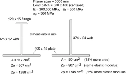
methods (plastic work)[4]. This research program is aimed at validating the limit state equations for single frames, determining the range of the validity, and exploring the way frames interact in grillages (see also [6,3,7,8]). The problem under study also applies to cases of hydrodynamic impact and other types of collisions. As a result, the research applies to most ship structures and many types of offshore structures. Ship structural design is changing. Traditionally, ship structures have been designed using ‘working stress’ methods. This approach considers the elastic stresses in a structure and sets limits on stresses. Consequently, the elastic properties of structures (e.g. moment of inertia, elastic section modulus) are controlled and optimized. Unfortunately, this approach does not assure that structures behave adequately in overload situations. To illustrate , consider the two frames sketched in Figure 1. The two frames have the same elastic section modulus, yet they have quite different plastic capacities.
Figure 1. Two frames with equal elastic modulus.
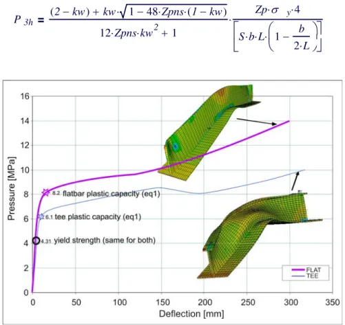
Figure 2 illustrates the different plastic behaviours of the two frames. The flat bar frame has greater initial capacity, followed by a greater reserve and more stable behaviour. The flat bar stays upright while the tee section folds over under high loads. Also shown in Figure 2 are the estimated plastic collapse values for the two frames. These values are found from equation (1), derived as part of the new IACS Polar
Rules. The terms are defined in the nomenclature. A full explanation is given in [5,6]. The above behaviour has broad implications. Clearly the elastic section modulus is not a measure of initial strength or ultimate reserve. The structural experiments are intended to explore the full elasto-plastic behaviour of frames.
P3h 2−kw ( )+ kw⋅ 1−48 Zpns⋅ ⋅(1−kw) 12 Zpns⋅ ⋅kw2+1 Zp⋅
σ
y⋅4 S b⋅ L⋅ 1 b 2 L⋅ −⎛⎜
⎝
⎞
⎠
⋅⎡⎢
⎣
⎤⎥
⎦
⋅ (1)Figure 2. Comparison of load-deflection behaviour of two equal modulus frames.
3. EXPERIMENTAL PROGRAM
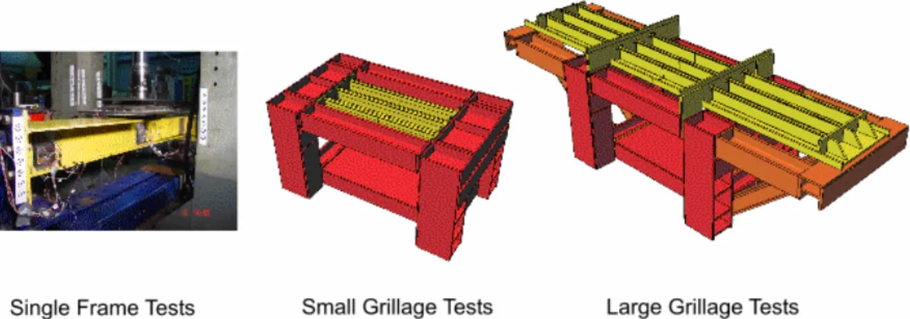
The program consists of several experimental phases (see Figure 3), each supported by numerical investigations. The first phase is the testing of a variety of single frames. The second phase is the testing of a grillage of three frames (small grillage). The third phase is the testing of a grillage of nine frames (large grillage).
The three experimental phases support each other in important ways. Ships frames are always part of a
structural system (a grillage). However, design and regulation normally consider single frames. The UR limit state equations were derived by considering a single frame in isolation. One of the aims of the current research is to understand the influence of boundary conditions on ship frame behaviour, especially in the plastic region. In preparation for the grillage tests, finite element analyses were used to examine the expected behaviours and compare the effects of different boundary conditions.
Figure 3. The three experimental phases in the ship frame research program Figure 4 shows the grillage support frame, with a
single frame in place. The support frame will be used to test two final single frames, the small grillages and the large grillages. Figure 5 shows the first of the small grillages ready for application of the strain gauges. Figure 6 shows a sketch of the data acquisition system for the single frame tests.
Figure 4. Preparations for testing final single frames in the grillage support frame.
Figure 5. Small grillage ready for application of strain gauges.
Figure 6. Data acquisition system for single frame tests.
4. FRAME ANALYSIS
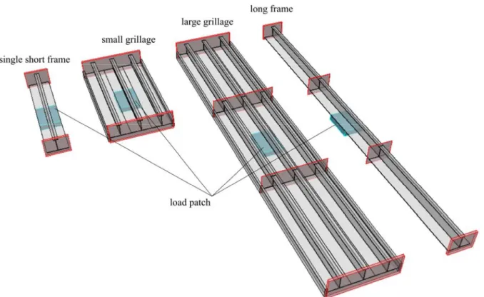
This section presents a variety of different finite element analyses. In all cases the frame (or frames) had the dimensions shown for the tee-75 frame in Figure 7. In all cases the frames were 2m long with a 150mm load patch. Figure 8. shows the geometry of the four finite element models: 1) single frame analysis (the standard case), 2) the small grillage case, which provides the central frame with more realistic side boundary conditions, 3) the large grillage, and 4) a single long frame (not to be tested experimentally). The large grillage provides the most realistic side and end boundary conditions for the central frame.
Figure 7. Basic Frame Dimensions for Single Frame Tests
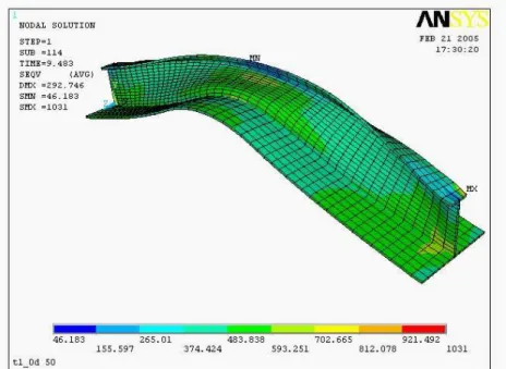
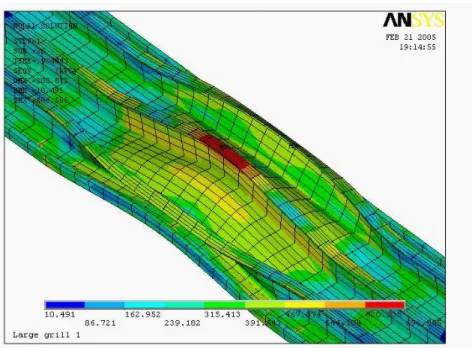
Figure 9 shows the deformation of the singe frame. Figure 10 shows the small grillage. Figure 11 shows the large grillage and Figure 12 shows the long single frame. It is interesting to note that the single and small grillage frames fall over (though only at large plastic deformation), while the long grillage and long single frame stay upright. The more compliant end conditions on the long frames presumably reduce the flange tension (as the ends pull in elastically) and
help to stabilize the flange. This is only one possible explanation. The experiments will likely have both more a concentrated load and small imperfections that will likely result in web folding. It will be interesting to see this experimental result (planned for fall 2005).
Figure 9. Single frame model with the load patch at a pressure of 9.483 MPa.
Figure 11. Large Grillage model with the load patch at a pressure of 18 MPa.
Figure 12. Long Frame model with the load patch at a pressure of 10 MPa.
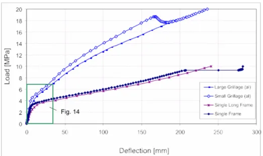
For each of the four configurations Figure 13 shows the load-deflection curves. Figure 14 shows just the initial part of the curves. The load in Figure 13 and 14 is just applied on the middle frame only. In that case the surrounding frames (if they exist) help support the frame. However, the neighboring frames
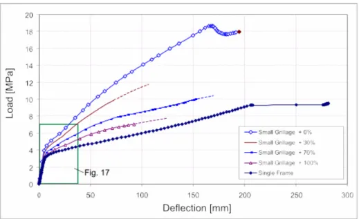
may be partially of fully loaded as well. Figure 15 shows a sketch of different neighboring frame loads. Figure 16 shows the load deflection relationship for the small grillage, with varying amounts of load on the adjacent frames. Figure 17 shows the initial part of the curves from Figure 16.
Figure 13. Comparison of the load-deflection curves for the four configurations.
Figure 14. Initial portion of the load-deflection curves for the four configurations.
Figure 16. Load-deflection curves for the small grillage with varying load % on neighboring frames.
Figure 17. Initial portion of the load-deflection curves for Figure 16.
5. DISCUSSION OF ANALYSIS
The above analysis has been done both to prepare for the grillage tests and to explore the differences between single and multiple frames. The results do show a number of very interesting results.
Figure 2 illustrates the value of examining plastic behaviour. The two frames would be considered identical by any standard based on the “working
this case the heavier flat bar frame would not get credit for its increased initial (linear) capacity, nor for its improved reserve. This presses the limits of the local buckling requirements, and results in a stiff but ‘brittle’ frame.
Most ship rule systems treat frame design in isolation, in that single frames are designed with simple assumptions about boundary conditions. Figure 13 shows the affect of modeling the
loaded frame and make it stronger and stiffer. Modeling longer sections results in a softer response, but no significant difference in strength. The small and large grillage experiments will show how accurate this analysis has been.
As a final point, it should be noted that large deflection plastic analyses are not always easy to obtain. When the web is quite thin and local buckling is probably, it is likely that ANSYS will not be able to give good results up to large deformations. On the other hand, when the sections are relatively thick and robust, ANSYS tends to give good and stable results up to very large deformations.
5. INITIAL EXPERIMENTAL
RESULTS
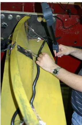
The single frame tests covered four frame types (and two load locations (central and end) (see Figure 7). Figure 18 shows the deformations of the tee-75 frame with a central load. Figure 19 shows the tee-50 frame being tested in the grillage support frame. Both the tee-75 and the tee-50 exhibited a plastic tripping behaviour at high loads (similar to the model in Figure 9).
Figure 20 shows the pattern of web collapse in the tee-75 frame with an end load.
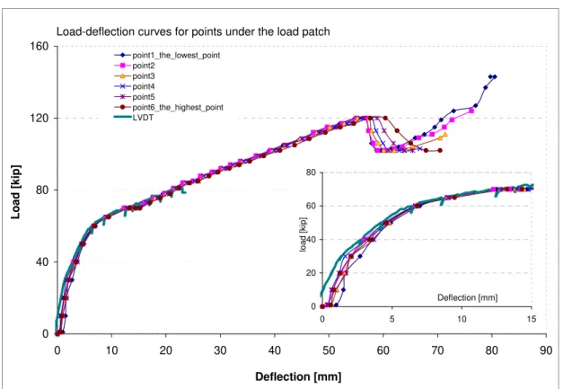
The load-deflection results for two end load cases are shown in Figure 21(tee-75) and Figure 22(flat-bar). The ‘point’ data was measured by the micro-scribe at six points across the web under the load, while the LVDT data was measured at the flange. Both frames have a clear transition form linear to non-linear, with the flat-bar showing smoother behaviour. The tee-75 frame exhibits a temporary loss of capacity after a region of large plastic deformation. This is the result of the flange tripping.
Figure 18. Tee-75 central load test.
Figure 19. Tee-50 central load test
Load-deflection curves for points under the load patch 0 40 80 120 160 0 10 20 30 40 50 60 70 80 90 Deflection [mm] Lo ad [ k ip] point1_the_lowest_point point2 point3 point4 point5 point6_the_highest_point LVDT 0 20 40 60 80 0 5 10 15 Deflection [mm] lo ad [k ip ]
Figure 21. Measured load-deflection curves for end-loaded tee-75 frame.
Load-deflection curves for points under the load patch
0 40 80 120 160 0 20 40 60 80 100 120 140 Deflection (mm) Loa d (k ip)
piont 6 - the lowest point point 5
point 4 point 3 point 2
point 1-the highest pint LVDT 0 20 40 60 80 0 5 10 15 Deflection (mm) Load (k ip)
6. CONCLUSIONS
The paper had described an investigation into the plastic behaviour of ship frames inter normal loads. The work is ongoing and will be more fully reported in the coming months. The series of experiments have examined the influence of boundary conditions. The various types of tests (single frames, small and large grillages) explore one aspect of the modeling boundary conditions, by physically incorporating more realistic support conditions. To date we have reasonably good agreement between ANSYS models and the single frame experimental results. We have modeled the grillage tests, to show us what we can expect in the coming experiments.
REFERENCES
1. ANSYS 6.0, Finite Element Program by SAS IP, Inc, 2001
2. IACS UR (Draft) I2 “Structural
Requirements for Polar Class Ships”, 30 July, 2003
3. Daley, C., “Review of the Tripping Requirements” Prepared for IACS Ad-hoc Group on Polar Class Ships and Transport Canada, Aug. 2003
4. Kendrick, A., and Daley, C.G., “Background Notes to Derivation and use of Formulations For Framing Design - IACS Unified Requirements for Polar Ships” Prepared for IACS Ad-hoc Group on Polar Class Ships and Transport Canada, January 2000
5. Daley, C.G., (2002), “Derivation of Plastic Framing Requirements for Polar Ships”, Journal of Marine Structures, Elsevier, 15(6) pp 543-559
6. Daley, C.G., (2002), “Application of Plastic Framing Requirements for Polar Ships”,
Journal of Marine Structures, Elsevier, 15(6) pp 533-542
7. Pavic, M., Daley, C., Hussein, A., Hermanski, “Ship Frame Research
Program-A Numerical Study of the Capacity of Single Frames Subject to Ice Load” OERC Report 2004-02, IOT Report TR-2004-04, Prepared for Transport Canada, March 2004
8. Daley, C., Hermanski, “Ship Frame Research Program- Investigation of Finite Element Analysis Boundary Conditions ” OERC Report 2005-02, IOT Report TR-2005-05, Prepared for Transport Canada, March 2005
SYMBOLS / NOTATION
IACS International Association of Classification Societies TC Transport Canada (Ship Safety) DRDC Defense Research and
Development Canada (Atlantic) USCG United States Coast Guard SSC Ship Structures Committee
(US-Canada Interagency Committee) A Frame x-sectional area
E Young’s modulus Et Post-yield tangent modulus
b height of the ice load patch hw height if the web
kw area ratio L length of frame
P3h pressure causing collapse for case
of 2 fixed supports S frame spacing tw thickness of web Zp plastic section modulus Zpns a non-dimensional modulus σy yield stress