HAL Id: hal-00707008
https://hal.archives-ouvertes.fr/hal-00707008
Submitted on 14 Jun 2012
HAL is a multi-disciplinary open access archive for the deposit and dissemination of sci-entific research documents, whether they are pub-lished or not. The documents may come from teaching and research institutions in France or abroad, or from public or private research centers.
L’archive ouverte pluridisciplinaire HAL, est destinée au dépôt et à la diffusion de documents scientifiques de niveau recherche, publiés ou non, émanant des établissements d’enseignement et de recherche français ou étrangers, des laboratoires publics ou privés.
Lyee Program Execution Patterns
Mohamed Ben Ayed
To cite this version:
Mohamed Ben Ayed. Lyee Program Execution Patterns. International Workshop on Lyee Methodol-ogy, 2002, France. pp.1. �hal-00707008�
Lyee
1Program Execution Patterns
Mohamed BEN AYEDUniversité Paris1 Panthéon Sorbonne CRI, 90 Rue de Tolbiac
75013 Paris, France
Abstract. The research undertaken aims to find regularities in Lyee program execution traces and to relate the trace chunks to well defined types of Lyee design situations. Our findings take the form of Lyee execution patterns, each pattern coupling a situation with a trace chunk. The paper presents and illustrate them with an example.
1. Introduction
Lyee-Sorbonne2 is a Franco-Japanese research project aiming at developing a methodology that supports software development in two steps, requirements engineering and code generation. The former is the contribution of the Sorbonne’s group whereas the latter is provided by LyeeALL.
The overall objective of the research activity of the Sorbonne Unit is to apply a method
engineering approach to the Lyee methodology [5,6]. The expected results consist on
formalising the product and the process aspects of the Lyee method, proposing improvements to guide the process and to contribute to the extension of the functionality of LyeeALL accordingly.
As a prerequisite of this method engineering activity, we developed a number of application examples using the Lyee method and the support of LyeeALL. This paper is a reflection on these experiments. It takes the form of a set of execution patterns that we discovered by analysing the program traces of the generated code for these examples. As any pattern, an execution pattern associates a problem to its solution. The problem is a
design situation typical of the Lyee way-of-thinking whereas the solution is a sequence of steps of the Lyee executed program. We identify eight patterns that, we think, are sufficient
to explain any Lyee program trace. In other words, any Lyee program execution trace is an aggregate of several of the 8 pattern traces.
The patterns show that there are regularities in the Lyee program execution control. Moreover, they allow us to relate a typical sequence of steps in program execution control to a well identified design situation. This was helpful to understand the key design situations to focus on during the requirements acquisition phase [9].
The paper presents the eight execution patterns and illustrate them with an example. The rest of the paper is organised as follows. Section 2 introduces the notion of Lyee program execution trace and the notations used to present a program trace in the patterns. Section 3 presents the execution patterns which are illustrated with an example in section 4.
1 Lyee, which stands for GovernmentaL MethodologY for SoftwarE ProvidencE, is a methodology for software
development used for the implementation of business software applications. Lyee was invented by Fumio Negoro.
2
This paper hereof is contributed to the Lyee International Collaborative Research Project sponsored by Catena Corp. and the Institute of Computer Based Software Methodology and Technology.
2. Tracing a Lyee Program Execution
In this section we first provide a brief overview of the Lyee program structure and execution control and then, introduce the notations to describe a Lyee program execution trace.
2.1. Lyee Program Execution Control
The Lyee approach and its support tool LyeeALL aim at transforming software requirements into code. The essence of the approach is to reduce software requirements to the description of program variables called words, and to generate the control structure that logically processes these variables and produces the expected result. Despite the traditional design approaches in which both the variables and the control structure of the program must be designed, LyeeALL generates the latter provided an appropriate description of the former is given. The underlying Lyee approach comprises an original
framework to structure programs, an engine to control their execution and a generation mechanism to generate programs from given requirements.
The Lyee engine controls the determination of words by executing a function, the Tense
Control Function on a program generated by LyeeALL. This program is an instance of a
generic model, the Process Route Diagram (PRD). The PRD provides the structural framework of Lyee programs whereas the Tense Control Function ensures the dynamic control of program execution.
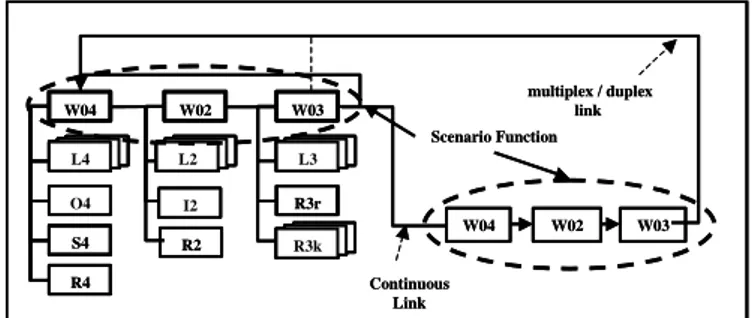
As shown in Figure 1, the structure of a Lyee program is a directed graph whose nodes are instances of a basic structure called Scenario Function. A Scenario Function (SF) is itself an aggregate of three sub-structures, called Pallets, W04, W02 and W03. Each pallet structure is further decomposed into sub-structures called Vectors. There are three types of vectors, Signification Vectors (Li), Action Vectors (I2, O4, S4) and Routing Vectors(Ri). Besides, there is a specific set of vectors for each pallet; for example pallet W04 has four vectors, L4, O4, S4 and R4. Finally each vector has an algorithmic structure which is a specialisation of the generic structure called the Predicate Structure [7] .
L4 O4 L 2 I2 L 3 L4L4 S4 R4 R3r W04 W02 W03 L 2L2 I2 L 3L3 R2 L 3L 3R3k multiplex / duplex link W04 W02 W03 Continuous Link Scenario Function L4 L4 O4 L 2 L 2 I2 L 3 L 3 L4L4 S4 R4 R3r W04 W02 W03 L 2L2 I2 L 3L3 R2 L 3L 3L 3R3k multiplex / duplex link W04 W02 W03 Continuous Link Scenario Function
Figure 1 : Lyee Program Execution Control
The Tense Control Function ensures the program control through Pallet Functions. The control is summed up in the following formula [6]:
TU = [ 4({L4,j},{O4, r },{S4, r }, R4) + 2({L2,i},{I2,r }, R2) + 3({L3,j},{R3,k})].
As expressed by the formula, the Tense Control Function may be defined as 4 + 2 + 3. In short, 4 controls the determination of output words and their physical presentation on a device such as a screen, 2 ensures the capture of input words whereas
3 aims at verifying the conditions under which the determination of output words is possible. Each pallet function controls the program execution thanks to its related vectors. It shall be noticed that the Routing Vectors are used to hand over the control either from one Pallet to another in the same SF or to another SF. The Routing Vectors R4, R2 and R3r allow to progress locally from one Pallet Function to another one in the same SF. Contrarily R3k Routing Vectors are used to hand over the control to another SF. There are three types of SF links which are handled by the Routing Vectors R3k : continuous, duplex and multiplex links. The former is a forward link whereas the two latter are backward links. A duplex link is required when words generated by the dependee SF must be transferred to dependent SF that starts its execution by Pallet Function 3. The multiplex link holds in case of no data transfer and the SF execution starts with Pallet Function 4.
2.2.Lyee Program Execution Trace
The purpose of program execution tracing is to provide an exact image of the sequence of steps by which the program transforms a set of inputs in a set of outputs. In the case of Lyee, the program execution trace has a predefined structure which is the one underlying the program execution control, namely the Tense Control Function. In fact, a Lyee program execution trace is an instance of the TU formula introduced above. Each step of the trace is
an instance of the TU formula element, e.g. L4.w for a step which produces the output word
w, R3r to hand over the control to the 4 of the same SF, L2.x for acquiring the input word x, etc…
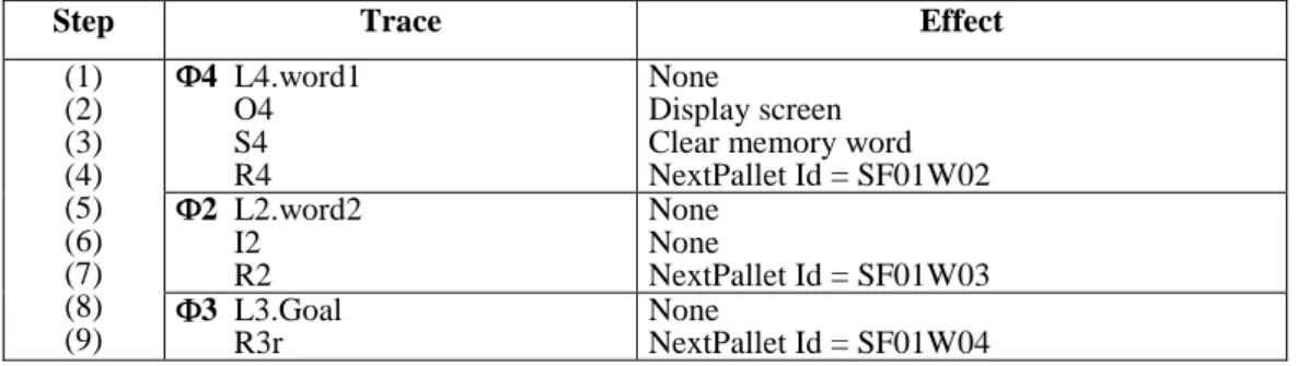
In the following, we present a Lyee program execution trace as a sequence of instantiated vectors. Figure 2 is an example of trace based on the notations summed up in Table1.
Notations Meaning
Li. word Instantiation of the Significant vector Li for “word” a Lb Execution of the pallet function a for vector Lb
I2 Input vector for pallet 2 O4 Output vector for pallet 4 S4 Structural vector
R4 Routing vector for pallet 4 R2 Routing vector for pallet 2 R3r, R3k Routing vector for pallet 3:
- r : recursive link
- k: continuous, duplex or multiplex link Table1 : Notations for Lyee Program Execution Tracing
As illustrated in Figure 2 below, the trace is presented in a table with three columns. The first indicates the step number, the second one provides the trace by reference to the vector executed at this step and the third one explains the effect of this execution. For instance in Figure 2, step 1 corresponds to the evaluation of the output word, word1 by the signification vector L4; in step 2 the O4 execution leads to display the screen, and step 4 hands over the control to Pallet W02.
Step Trace Effect (1) (2) (3) (4) (5) (6) (7) (8) (9) 4 L4.word1 O4 S4 R4 None Display screen Clear memory word NextPallet Id = SF01W02 2 L2.word2 I2 R2 None None NextPallet Id = SF01W03 3 L3.Goal R3r None NextPallet Id = SF01W04 Figure 2 : Trace Example
3. Execution Patterns
This section presents the eight Lyee program execution patterns. Patterns have been introduced in software engineering as a mean to capture a solution applicable to a problem in a given context. A pattern identifies a problem which occurs again and again and provides a generic solution that can be recurrently applied to solve the problem. In [1], Alexander defines a pattern as describing “a problem which occurs over and over again in our environment and then describes the core of the solution to that problem, in such a way that you can use this solution a million times over, without ever doing it the same way twice”. A large number of similar definitions of the term “pattern” exists today [2,3,4]. All these definitions share two main ideas. First, a pattern relates a recurring problem to its
solution. Second, each problem has characteristics that distinguish it from other problems.
3.1. Lyee Execution Pattern Structure
The Lyee execution patterns presented in this section aim at identifying sequences of steps which occur again and again in the execution of Lyee programs. Each pattern associates a
sequence of steps to the situation in which this sequence is executed.
A sequence of steps is expressed using the trace notations introduced before. Every of
the sequence of steps of the eight patterns can be found as parts of a SF execution.
The corresponding situation shall thus characterise the SF in some way. To achieve this objective, we propose to view any SF as a state transition (Figure 3) that transforms a set of words (Wbefore) into another set of words (Wafter), provided some input words (Wi). A
pattern situation characterises the transition through conditions expressed on the three types of words Wbefore,Wi andWafter .
W before W after
Wbefore Wafter
Wi
Figure 3 : The semantic view of a Scenario Function
The state before is defined by the set of words called Wbefore that, if not empty, has been
determined by previous executions of one or several SFs. The state after is defined by a set of new input and/or output words called Wafter resulting from the SF execution. As shown in
Figure 3, the transition requires some input words called Wi from the external world (user
world or database world). Words of Wi can be captured in one shot or in several
asynchronous steps. This refers to the fact that the transition may encompass one or several interactions with the external world. In other words, the SF is related to a state transition
including at least one interaction with the external world but may comprise several ones. We will see later on the influence of this on the program trace.
Every pattern is presented in the following in two parts (a) the situation in which it is applicable and, (b) the typical sequence of steps of program execution corresponding to this situation. In each part, the situation and the sequence of steps respectively, are presented and then, commented.
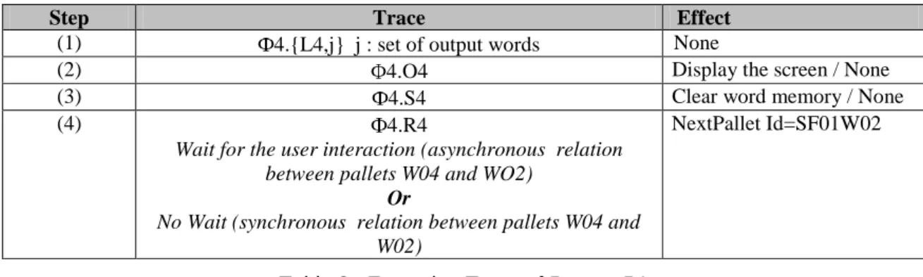
3.2. Pattern P1: Start of an Independent Scenario Function
Situation: W before =
We qualify this SF as independent because its execution does not depend on previous SF executions.
Execution trace :
Step Trace Effect
(1) 4.{L4,j} j : set of output words None
(2) 4.O4 Display the screen / None
(3) 4.S4 Clear word memory / None
(4) 4.R4
Wait for the user interaction (asynchronous relation between pallets W04 and WO2)
Or
No Wait (synchronous relation between pallets W04 and W02)
NextPallet Id=SF01W02
Table 2 : Execution Trace of Pattern P1
The main characteristic of the trace presented in Table 2 is that one execution of the 4 pallet function is sufficient to trigger a successful execution of the 2 pallet function (in the sense that it allows capturing the input). The 4 pallet execution leads to displaying the empty screen (in the case where the SF is typed screen) and to clear the word memory.
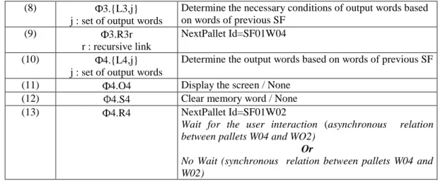
3.3. Pattern P2: Start of a Dependent Scenario Function
Situation: W before
We qualify this SF as dependent because the SF execution depends of words determined previously by the execution of other SFs.
Execution trace :
Step Trace Effect
(1) 4.{L4,j}
j : set of output words
None
(2) 4.O4 None
(3) 4.S4 None
(4) 4.R4 NextPallet Id=SF01W02
(5) 2.{L2,i}
i : set of input words
None
(6) 2.I2 None
(8) 3.{L3,j} j : set of output words
Determine the necessary conditions of output words based on words of previous SF
(9) 3.R3r
r : recursive link
NextPallet Id=SF01W04
(10) 4.{L4,j}
j : set of output words
Determine the output words based on words of previous SF
(11) 4.O4 Display the screen / None
(12) 4.S4 Clear memory word / None
(13) 4.R4 NextPallet Id=SF01W02
Wait for the user interaction (asynchronous relation between pallets W04 and WO2)
Or
No Wait (synchronous relation between pallets W04 and W02)
Table 3 : Execution Trace of Pattern P2
The trace presented in Table 3 shows that the words of the state before can be determined only at the second execution of the pallet function 4. The first iteration of the sequence of pallets 4, 2, 3 does not have visible effects but is a prerequisite for the second iteration to happen and be succesful. The effects of the second iteration start with the 4.L4 execution that can determine the words of Wbefore.
3.4. Pattern P3: Input Word Capture
Situation : Wi
The situation refers to the fact that the transition must capture input words. Therefore, this situation shall occur in any SF execution implementing a complete interaction with the user, as the assumption is that the transition includes at least one capture of input words from the external world.
Execution trace :
Step Trace Effect
(1) 2.{L2,i}, i : input words None
(2) 2.I2 Read the input from physical device
(3) Loop NextPallet Id=SF01W02
(4) 2.{L2,i}, i : input words Determine the input words (from buffer)
(5) 2.I2 None
(6) 2.R2 NextPallet Id=SF01W03
(7) 3.{L3,j}, j : output word None
(8) 3.R3r
(or 3.R3c, c : continuous link)
NextPallet Id = SF01W04
Table 4 : Execution Trace of Pattern P3
The trace presented in Table 4 indicates that two iterations of the pallet function 2 are needed to successfully capture the input words. The first iteration makes the physical
read action feasible whereas the second uses the buffer filled in by the read action to
actually determine the input words. The control is then given to pallet 3.
3.5. Pattern P4: Output Word Production
This situation indicates that Wafter depends of Winput . This situation shall occur in any
SF execution implementing a complete interaction with the user (or interfacing a program with a database).
Execution trace :
Step Trace Effect
(1) 3.{L3,j}, j : output words Determine the necessary conditions of output words (2) 3.R3r (r : recursive link) NextPallet Id=SF01W04
(3) 4.{L4,j}, j : output words Determine the output words dependent of the input words (4) 4.O4 Display the screen / Write in the database
(5) 4.S4 Clear word memory / None
(6) 4.R4 NextPallet Id=SF01W02
Wait for the user interaction (asynchronous relation between pallets W04 and WO2)
Or
No Wait (synchronous relation between pallets W04 and W02)
Table 5 : Execution Trace of Pattern P4
As shown in Table 5, the pattern indicates that in the production of output words, the execution of the pallet function 3 determining the necessary conditions of the output words is followed by the execution of the pallet function 4 implementing physically the write operation on the corresponding device.
3.6. Pattern P5: Dependent Output Word Production
Situation : j1 W after and {j: j W after and j = fj(j1) }
The characteristic of this situation is that some of the output words produced in the SF are intermediate values which are not displayed to the user.
This situation addresses dependencies among output words belonging to W after. More
precisely the situation identifies a dependence of the type n to 1 : n output words {j} belonging to W after are dependent of only 1 word j1 in the same W after .
This situation imposes an ordering in the calculation of output words, which is reflected in the pattern sequence of steps.
Execution trace :
Step Trace Effect
(1) 3.{L3,j}
j : output words
determine the necessary conditions of output words j1 and {j} (2) 3.R3r r : recursive link NextPallet Id=SF01W04 (3) 4.{L4,j1} j1 : output words
Determine the output word j1 dependent of the input words
(4) 4.O4 None
(5) Loop NextPallet Id=SF01W04
(6) 4.{L4,j}
{j} : dependent output words
Determine the output words {j}
(7) 4.O4 Display the screen / Write in the database
(8) 4.S4 Clear word memory / None
(9) 4.R4 NextPallet Id=SF01W02
Wait for the user interaction (asynchronous relation between pallets W04 and WO2)
Or
No Wait (synchronous relation between pallets W04 and W02)
The key characteristic of a sequence of steps presented in Table 6 is a double execution of the 4 pallet function : one for determining the dependee word (j1) and one for determining the set of dependent words. It shall be noticed that two iterations are sufficient, even if the set of dependent words {j} comprises more than one word.
3.7. Pattern P6 : Termination of a SF Execution
Situation: Wafter is determined
The situation refers to the fact that the word Wafter have already been evaluated. Execution trace :
Step Trace Effect
(1) 4.{L4,j}
j : set of output words
Already determined
(2) 4.O4 None
(3) 4.S4 None
(4) 4.R4 NextPallet Id=SF01W02
(5) 2.{L2,i}
i : set of input words
Already determined
(6) 2.I2 None
(7) 2.R2 NextPallet Id=SF01W03
(8) 3.{L3,j}
j : set of output words
Already satisfied
(9) 3.{R3,k}
k : continuous, duplex or multiplex
End of the Scenario Function SF01.
Table 7 : Execution Trace of Pattern P6
As shown in table 7, a SF termination is detected when one iteration of the three pallet functions induces no change compared to the previous iteration. Consequently the pattern trace is made of a series of steps reflecting that the three pallet function executions have no effect.
3.8. Pattern P7 : Mono Interaction
Situation : W i = Capture one shot (W i1)
As shown in Figure 4 the situation of this pattern refers to a transition in which a single set of input words is captured in one shot. Such an SF is called atomic.
i1
W before W
W before W after
Word
Figure 4 : Single Interaction
Execution Trace = ( P1 | P2 ) + [P3] + [ P4 + (P5)* ] +P6
In this formula, the name of a pattern is used instead of the complete execution trace corresponding to it. The vertical bar expresses that the left item and right item can be substituted one to the other. A bracket means that the item is optional. Finally, the plus operator expresses the trace concatenation. Pattern P7 is a compound pattern which provides the composition of patterns in a transition with one single interaction.
Pattern P1 or Pattern P2 are applied to Start the execution of the transition; the pattern P3 is applied to capture the set of input words Wi1.The pattern P4 or the pattern P5 (several
times) are then be applied in order to calculate the output words; depending of the fact that they are dependent, or not of the others words. Pattern P6 ends the transition.
3.9. Pattern P8 : Multi – Interaction
Situation : Wi = j Capture one shot (W ij)
i1
before
Wbefore W
after
Wordbefore Wordafter
Word
...
iN Word
Figure 5: Multi-Interaction
The situation refers to in this pattern is the one of a compound SF. The term compound is employed here to express the fact that within the same SF, several interactions are performed to capture the input words (Figure 5).
Execution Trace = (P1 | P2) +([P3] + [ P4 + (P5)* ])N + P6
This pattern is similar to P7 but corresponds to the execution a compound SF. The sequence of steps it refers to is an aggregate of other pattern sequences of steps .
4. Applying Patterns
In order to illustrate the execution patterns, we present the Split a Goal example. Some other examples can be found in [8]. Split a Goal is a functionality which, given a goal statement such as ‘Withdraw cash from an ATM’, automatically decomposes it into a verb and its parameters. For example, Withdraw is the verb, cash is the target parameter of the verb and from an ATM is the means parameter.
The full functionality identifies 7 different parameters. However, in this paper we will consider only the two parameters exemplified above, target and means.
The Split a Goal example includes two screens: the Input screen (Screen1) lets the user input the goal and inquiry for its decomposition (Figure 6). The Output screen (Screen2) displays the values of the parameters resulting of the decomposition of the goal (Figure 7). When the user clicks on the SearchDB button, the system accesses to the database using the
GoalId as query parameter and retrieves the goal name which is displayed to the user in the Goal field. Screen1 Goal_ID SearchDB Goal Split Quit Goal_ID SearchDB Goal : Split Quit
Figure 6: The Input screen to formulate the goal
Screen2 Verb : Target : Means : Stop Return Goal Split Verb : Target : Means : Stop Return Goal Split
Figure 7: The Output screen to display the parameters
When the user clicks on the Split button, the system decomposes the goal into a Verb and its parameters (Target, Means) using an algorithm, and displays the results on the
Output screen (Figure 7). The Return button triggers the display of the input screen
whereas the Stop button allows the user to stop the process at any moment.
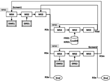
The PRD presented in Figure 8 is composed of three Scenario Functions namely SF01 (associated to Screen 1), SF02 (for accessing the database) and SF03 (for displaying outputs in Screen 2): W04 W02 W03 W04 W02 W03 SW01 SR01 SW02 SR02 R3c
R3e End R3e End
R3m Screen1 Screen2 W04 W02 W03 GoalDB R3c FR01 R3d KR01 SF01 SF02 SF03 W04 W02 W03 W04 W02 W03 SW01 SR01 SW02 SR02 R3c
R3e End R3e End
R3m Screen1 Screen2 W04 W02 W03 GoalDB R3c FR01 R3d KR01 SF01 SF02 SF03
Figure 8: Process Route Diagram for Split a Goal example
Table 8 presents the execution trace, column 2 relates a sequence of steps in the trace to one of the 8 patterns.
Step Pattern Applied Trace Effect (1) (2) (3) (4) (5) (6) (7) (8) (9) (10) (11) (12) (13) (14) (15) (16) (17) (18) P8 P1 4 L4.Goal O4 S4 R4
Wait until the user action
None Display screen Clear memory word NextPallet Id = SF01W02
The user clicks on SearchDB button
P3 2 L2.Goal_ID, L2.SearchDB L2.Split, L2.Quit I2 Loop None None
Capture input from screen NextPallet Id = SF01W02
2 L2.Goal_ID, L2.SearchDB
L2.Split, L2.Quit I2
R2
Determine Input word (from buffer) Determine Input word (from buffer) None
NextPallet Id = SF01W03
3 L3.Goal
R3c (continous link)
Determine the necessary condition NextPallet Id = SF02W04
end of execution of SF01 (break) (19) (20) (21) (22) (23) (24) (25) (26) (27) P7 P2 4 L4.Key_GoalID O4 S4 R4 None None None NextPallet Id = SF02W02 2 L2.Goaldb I2 R2 None None NextPallet Id = SF02W03 3 L3.Key_GoalID R3r
Determine the necessary condition NextPallet Id = SF02W04 (28) (29) (30) (31) (32) (33) (34) 4 L4.Key_GoalID O4 S4 R4
Determine Output word None None NextPallet Id = SF02W02 P3 2 L2.Goaldb I2 Loop None
Capture input from database NextPallet Id = SF02W02
(35) (36) (37) (38) (39) 2 L2.Goaldb I2 R2
Determine input word from buffer None NextPallet Id = SF02W03 3 L3.Key_GoalID R3r Already Satisfied NextPallet Id = SF02W04 (40) (41) (42) (43) (44) (45) (46) (47) (48) P6 4 L4.Key_GoalID O4 S4 R4 Already determined None None NextPallet Id = SF02W02 2 L2.Goaldb I2 R2 Already determined None NextPallet Id = SF02W03 3 L3.Key_GoalID R3d (duplex link) Already satisfied NextPallet Id = SF01W03 end of execution of SF02 (49) (50) P8 P4 3 L3.Goal R3r
(return of the duplex link)
Already determined NextPallet Id = SF01W04 (51) (52) (53) (54) (55) (56) (56) (57) (58) (59) (60) (61) (62) (63) (64) (65) (66) (67) 4 L4.Goal O4 S4 R4
Wait until the user action
Determine output word Display screen Clear memory word NextPallet Id = SF01W02 The user clicks on the Split button
P3 2 L2.Goal_ID, L2.SearchDB L2.Split, L2.Quit I2 Loop None None
Capture input from screen NextPallet Id = SF01W02
2 L2.Goal_ID, L2.SearchDB
L2.Split, L2.Quit I2
R2
Determine Input word (from buffer) Determine Input word (from buffer) None NextPallet Id = SF01W03 3 L3.Goal R3r Already satisfied NextPallet Id = SF01W04 (68) (69) (70) (71) (72) (73) (74) (75) (76) (77) (78) (79) P6 4 L4.Goal O4 S4 R4 Already determined None None NextPallet ID = SF01W02 2 L2.Goal_ID, L2.SearchDB L2.Split, L2.Quit I2 R2 Already determined Already determined None NextPallet Id = SF01W03 3 L3.Goal R3c (continous link) Already satisfied NextPallet Id = SF03W04 end of execution of SF01 (80) (81) (82) (83) (84) (85) (86) (87) (88) (89) (90) (91) (92) (93) P7
P2 4 L4.Verb, L4.Target, L4.Means
O4 S4 R4 None None None NextPallet Id = SF03W02 2 L2.Stop, L2.Return I2 R2 None None NextPallet Id = SF03W03
3 L3.Verb, L3.Target, L3.Means
R3r
Determine the necessary condition NextPallet Id =SF03W04 (94) (95) (96) (97) (98) (99) (100) (101) (102) (103) (104) (105) (106) (107) (108) (109) (110) (111)
4 L4.Verb, L4.Target, L4.Means
O4 S4 R4
Wait until the user action
Determine output word Display screen Clear memory word NextPallet Id = SF03W02
The user clicks on the Return button
P3 2 L2.Stop, L2.Return
I2
Loop
None
Read input from input screen NextPallet Id = SF03W02
2 L2.Stop, L2.Return
I2 R2
Determine input word None
NextPallet Id = SF03W03
3 L3.Verb, L3.Target, L3.Means
R3r Already satisfied NextPallet Id = SF03W04 (112) (113) (114) (115) (116) (117)
P6 4 L4.Verb, L4.Target, L4.Means
O4 S4 R4 Already determined None None NextPallet Id = SF03W02
(118) (119) (120) (121) (122) (123) (124) (125) 2 L2.Stop, L2.Return I2 R2 Already determined None NextPallet Id = SF03W03
3 L3.Verb, L3.Target, L3.Means
R3m (multiplex link) Already satisfied NextPallet Id = SF01W04 end of execution of SF03 (126) (127) (128) (129) (130) (131) (132) (133) (134) (135) (136) (137) (138) (139) (140) (141) (142) (143) P7 P1 4 L4.Goal O4 S4 R4
Wait until the user action
None Display screen Clear memory word NextPallet Id = SF01W02
The user clicks on the Quit button
P3 2 L2.Goal_ID, L2.SearchDB L2.Split, L2.Quit I2 Loop None None
Capture input from screen NextPallet Id = SF01W02
2 L2.Goal_ID, L2.SearchDB
L2.Split, L2.Quit I2
R2
Determine Input word (from buffer) Determine Input word (from buffer) None NextPallet Id = SF01W03 3 L3.Goal R3r None NextPallet Id = SF01W04 (144) (145) (146) (147)(148) (149) (150) (151) (152) (153) (154) (155) P6 4 L4.Goal O4 S4 R4 None None None NextPallet Id = SF01W02 2 L2.Goal_ID, L2.SearchDB L2.Split, L2.Quit I2 R2 Already determined Already determined None NextPallet Id = SF01W03 3 L3.Goal
R3e (continuous link)
Already satisfied NextPallet Id = END
end of execution of program Table 8: Relating Split a Goal Trace to Patterns
Table 8 shows that the trace is composed of 14 parts each corresponding to a sequence of steps of one of the six atomic patterns P1 to P6.
In addition, the table shows that groups of sequences of steps conform to the compound patterns P7 and P8. For example, it can be seen that the trace starts with an instance of the P8 pattern, followed by two instances of pattern P7.
The instance of pattern P8 conforms the P8 template : it is composed of a sequence of atomic patterns instances : P1, P3, P4, P3 and P6.
5. Conclusion
This paper reflects on our experience with LyeeALL. It proposes generic Lyee program execution traces captured in Lyee execution patterns. Each pattern identifies a recurrent sequence of steps in Lyee program execution control and to relate it to the situation in which this sequence shall be executed.
Any Lyee program execution trace results of the assembly of pattern sequences. In other words, any Lyee program execution trace is an aggregation of instances of some of these execution patterns. This was shown in the Split a Goal example. The execution patterns were useful to understand the relevant design situations when drawing PRDs. Based on these situations a set of design patterns have been defined and are currently under validation.
6. References
[1] C. Alexander, S. Ishikawa, M. Silverstein, M. Jacobson, I. Fiksdahl-King, S. Angel, “A Pattern
Language”, Oxford University Press, New York, 1977.
[2] J. Coplien, D. Schmidt (eds.), “Pattern Languages of Program Design”, Addison Wesley, Reading, MA, 1995.
[3] M. Fowler, “Analysis Patterns: Reusable Object Models”, Addison-Wesley, 1997.
[4] E. Gamma, R. Helm, R. Johnson, J. Vlissides, “Design Patterns: Elements of Reusable Object-Oriented
Software”, Addison Wesley, Reading, MA, 1995.
[5] F. Negoro, “Intent Operationalisation For Source Code Generation”, Proceedings of SCI and ISAS, Orlando, 2001.
[6] F. Negoro, “Methodology to define software in a deterministic manner”, Proceedings of ICII, Beijing, China, 2001.
[7] F. Negoro, “The predicate structure to represent the intention for software”, Proceedings of SNPD, Nagoya, Japan, 2001.
[8] S. Nurcan, M. Ben Ayed, C. Rolland, Lyee International Collaborative Project University Paris 1 Scientific Report SC1, Mars 2002
[9] C. Rolland, M. Ben Ayed, “Understanding the Lyee Methodology through Meta Modelling”, Proceeding of EMMSAD, Toronto, 2002.