HAL Id: cea-02528443
https://hal-cea.archives-ouvertes.fr/cea-02528443
Submitted on 1 Apr 2020
HAL is a multi-disciplinary open access
archive for the deposit and dissemination of
sci-entific research documents, whether they are
pub-lished or not. The documents may come from
teaching and research institutions in France or
abroad, or from public or private research centers.
L’archive ouverte pluridisciplinaire HAL, est
destinée au dépôt et à la diffusion de documents
scientifiques de niveau recherche, publiés ou non,
émanant des établissements d’enseignement et de
recherche français ou étrangers, des laboratoires
publics ou privés.
nanoparticles: a comparative study
Michael Delalande, Pierre Marcoux, Peter Reiss, Yves Samson
To cite this version:
Michael Delalande, Pierre Marcoux, Peter Reiss, Yves Samson. Core–shell structure of chemically
synthesised FePt nanoparticles: a comparative study. Journal of Materials Chemistry, Royal Society
of Chemistry, 2007, 17 (16), pp.1579-1588. �10.1039/b614209e�. �cea-02528443�
Core-shell structure of chemically synthesised FePt nanoparticles: a comparative study Michaël Delalande,Pierre R. Marcoux,Peter Reiss and Yves Samson
We conducted a comparative study about solution synthesis of FePt nanoparticles through different chemical processes, using four "hot soap methods" and one polyol process.
2 | J. Mater. Chem., 2006, [vol], 00–00 This journal is © The Royal Society of Chemistry [year]
Core-shell structure of chemically synthesised FePt nanoparticles: a
comparative study†
Michaël Delalande,
aPierre R. Marcoux,
bPeter Reiss
*
band Yves Samson*
aReceipt/Acceptance Data [DO NOT ALTER/DELETE THIS TEXT] Publication data [DO NOT ALTER/DELETE THIS TEXT] 10
DOI: 10.1039/b000000x [DO NOT ALTER/DELETE THIS TEXT]
We carried out solution synthesis of FePt nanoparticles through different chemical methods, using four “hot soap methods”, i.e. the particle formation in the presence of surfactant molecules at high temperatures, and one polyol process. Structural and magnetic properties of the as-made particles pointed to a core-shell structure for the particles prepared with hot soap methods, with an iron-15
depleted core surrounded by a pure iron shell. Such a structure has an impact on the magnetic properties of as-made particles since Fe atoms from shell are oxidised and non magnetic. We proved however that iron atoms of this shell are available during the formation of the ordered phase upon annealing: L10 phase for small particles, L12 for bigger ones. In contrast, the core-shell structure was not observed in the case of nanoparticles synthesised according to the polyol process. 20
This outlines the key role of the stabilising ligands, long alkyl chain surfactants in the former case and tetraethylene glycol in the latter.
Introduction
Chemical methods have been widely used to produce nanosized materials due to their straightforward nature and 25
their potential to prepare large quantities of the final product.1 Furthermore, they provide particles that are easily dispersible in liquid media, and therefore give the opportunity to fabricate nanostructured devices through self-assembly.2
The synthesis of discrete magnetic nanoparticles with sizes 30
ranging from to 2 to 20 nm is of significant importance, because of their applications in Tbit.in-2 magnetic storage devices3 and in biotechnologies.4 The superparamagnetism limit makes it necessary to use highly anisotropic materials. Among magnetic metallic alloys, the FePt alloy in the L10 35
phase is a prominent candidate. This ordered phase has indeed a very high uniaxial anisotropy, Ku = 7×10⁶ J/m3, so that the critical diameter, below which thermal fluctuations induce random switching of the magnetisation direction, is as small as 3.5 nm.
40
For this reason, many processes for the chemical synthesis of nanometer-sized FePt nanoparticles have been developed. First of all these reactions aim at monodisperse particles, in order to facilitate subsequent self-assembly, and to yield homogeneous magnetic properties of particles. Secondly, 45
these reactions should provide size-tunable particles, with a diameter large enough compared to the critical diameter. Thirdly, the stoichiometry should be as close to Fe50Pt50 as possible since the chemically ordered L10 phase, with a high
magnetocrystalline anisotropy, includes as many Fe atoms as 50
Pt atoms. Finally, the as-made particles should be readily dispersible in common solvents, because self-assembly phenomena are sensitive to aggregation. Furthermore, in some cases size-selection steps are necessary and such processes require also a good solubility. The first reported protocol 55
mentioned in 2000 the synthesis of FePt nanoparticles in a high-boiling coordinating solvent. It was later called “hot soap method” since the formation of metallic Fe and Pt atoms was performed in presence of surfactant molecules. 5 A similar method was subsequently extended to the synthesis of another 60
binary alloy (CoPt),6 and then to ternary alloys (FePtAg).7 Most of the solution synthesis methods of FePt nanoparticles are based on the transformation of an iron precursor and a platinum precursor into the metallic state, in presence of two surfactant molecules (one that preferentially 65
binds to Fe surface atoms, another one for Pt). The latter are in charge with stabilising metallic nuclei in solution by preventing aggregation during growth. Precursors may be either organometallic (Fe0 in iron pentacarbonyl for example) or ionic (e. g. PtII in platinum acetylacetonate). The use of an 70
oxidised metal as a precursor implies the presence of a reducing agent, a strong one if FeII and PtII have to be reduced,8 a milder one if just PtII needs to be reduced. Due to their higher reduction potential (1.2 V vs. -0.4 V), platinum salts can easier be reduced as compared to iron salts. In some 75
cases, the reducing agent may be the solvent,9 or one of the metallic precursors.10 As a conclusion, let us notice that there are very few hot soap reactions involving an organometallic Pt0 precursor.
Since iron pentacarbonyl is highly flammable and very 80
toxic, alternative methods have soon been developed, in which this Fe precursor was replaced by an ionic iron precursor such as FeCl2 or Fe(acac)2. In addition, with the goal to facilitate chemical ordering of the FePt alloy particles during the synthesis, attempts were made to slow down the growth 85
a CEA, DRFMC, Nanostructure and Magnetism, 17 rue des Martyrs 38054 Grenoble, France. Fax: 33 4 38 78 51 97; Tel: 33 4 38 78 35 62; E-mail: yves.samson@cea.fr
b CEA, DRFMC, SPrAM (UMR 5819 CNRS-CEA-UJF), 17 rue des Martyrs 38054 Grenoble, France Fax: 33 4 38 78 50 97; Tel: 33 4 38 78 97 19; E-mail: peter.reiss@cea.fr
† Electronic Supplementary Information (ESI) available: X-Ray diffractograms of as-made and annealed nanoparticles; TEM micrographs and diameter distribution histograms of as-made particles. See http://dx.doi.org/10.1039/b000000x/
kinetics. This led to the development of polyol processes. A kinetic control is indeed easier to achieve in a polyol (ethylene glycol, EG, or tetraethylene glycol, TEG, for example), acting simultaneously as the solvent, the reducing agent and the stabilising ligand.11
90
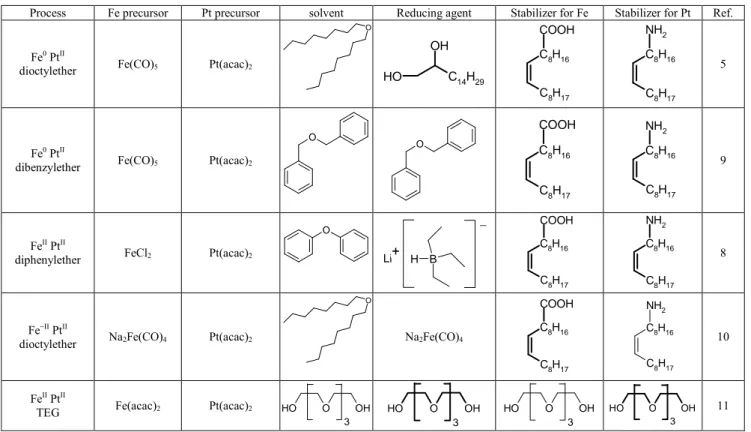
In the present study, we compared four hot soap methods and a polyol process using TEG. These five methods are summarised in Table 1. The first process, using Fe0 and PtII in dioctylether, was the first synthesis of FePt nanoparticles described, and is still today the most common in literature. In 95
the second method, dibenzylether acts simultaneously as solvent and reducing agent for the Pt precursor. The third process uses an ionic precursor of iron and therefore requires a strong reducing agent, lithium hydride. In the fourth method, the most recent one, the Pt precursor is reduced by the Fe 100
precursor. Finally, in the polyol process, TEG is at the same time the solvent, the reducing agent and the stabilising ligand. For every method, we will characterize structurally and magnetically as-made and annealed particles, so that we can highlight the major differences between all synthesis 105
reactions.
Experimental
Nanoparticles’ preparation by the Fe0 PtII dioctylether method5
A stirred mixture of Pt(acac)2 (197 mg; 0.5 mmol) and 1,2-110
hexadecanediol (388 mg; 1.5 mmol) in dioctylether (15 mL; 12.105 g) is heated under argon to 100°C with a 12°C/min rate. After 15 minutes at 100°C, all the powder has been dissolved and the solution is slightly yellow coloured. Then a solution of Fe(CO)5 (196 mg; 1 mmol), oleylamine (134 mg; 115
0.5 mmol) and oleic acid (141 mg; 0.5 mmol) in dioctylether (5 mL; 4.035 g) is injected into the solution containing Pt(acac)2 while vigorously stirring. As soon as the reaction temperature comes back to 100°C, temperature is set to 295°C with a 10°C/min rate. After 30 minutes of reflux, the reaction 120
mixture is cooled down to room temperature. Then 80 mL of anhydrous ethanol are added, in order to precipitate the particles. They are centrifuged, then dissolved in toluene (20 mL) containing both stabilising ligands (oleic acid and oleylamine; 50 µL of each). 40 mL of anhydrous ethanol are 125
added for the second precipitation step. After centrifugation, the FePt nanoparticles are dispersed in toluene (20 mL) with both surfactants (50 µL of each). The long-term stability of the obtained black dispersion is more than 1 year without a sign of precipitation.
130
Nanoparticles’ preparation by the Fe0 PtII dibenzylether method9
A stirred mixture of Pt(acac)2 (296 mg; 0.75 mmol) and dibenzylether (15 mL; 15.645 g) is heated under argon from room temperature to 240°C with a 5°C/min rate. When the 135
temperature of the solution reaches 100°C, Fe(CO)5 (294 mg; 1.5 mmol), oleylamine (1.607 g; 6 mmol) and oleic acid (1.697 g; 6 mmol) are injected. The temperature is then kept at 240°C for 1 hour, raised to 280°C with a 5°C/min rate and maintained at this value for 2 hours. During this reflux stage, 140
a colourless liquid is distilled from reaction mixture. This liquid is composed of toluene and benzaldehyde. The reaction mixture is subsequently cooled down to room temperature and the particles are precipitated by adding 80 mL of anhydrous ethanol. They are purified in the same way as in the Fe0 PtII 145
dioctylether method.
Table 1 The different chemical syntheses investigated in the present study.
Process Fe precursor Pt precursor solvent Reducing agent Stabilizer for Fe Stabilizer for Pt Ref.
Fe0 PtII
dioctylether Fe(CO)5 Pt(acac)2
O C 14H29 O H OH C8H17 C8H16 COOH C8H17 C8H16 NH2 5 Fe0 PtII
dibenzylether Fe(CO)5 Pt(acac)2
O O C8H17 C8H16 COOH C8H17 C8H16 NH2 9 FeII PtII
diphenylether FeCl2 Pt(acac)2
O B H Li+ _ C8H17 C8H16 COOH C8H17 C8H16 NH2 8 Fe−II PtII
dioctylether Na2Fe(CO)4 Pt(acac)2
O Na2Fe(CO)4 C8H17 C8H16 COOH C8H17 C8H16 NH2 10 FeII PtII
TEG Fe(acac)2 Pt(acac)2 HO O OH
3 O O H OH 3 O O H OH 3 O O H OH 3 11
4 | J. Mater. Chem., 2006, [vol], 00–00 This journal is © The Royal Society of Chemistry [year] Spectroscopic data of distilled fraction. FTIR: υmax/cm
-1 3028, 2922 and 2856 (toluene), 2816 and 2734 (benzaldehyde), 1702vs (CO benzaldehyde), 1596 (benzaldehyde), 1496 (toluene), 1202s (benzaldehyde), 1076, 1030 and 728vs 150
(toluene). NMR: δH (200 MHz; CDCl3; Me4Si) 2.24 (s, CH3 of toluene), 7.06, 7.09, 7.13, 7.15, 7.19, 7.20, 7.26, 7.30, 7.33 (m, aromatic protons of toluene and benzaldehyde), 7.67 (dd, CH=CH−C−CHO), 9.77 (s, Ar−CHO).
Nanoparticles’ preparation by the FeII PtII diphenylether 155
method8
Diphenylether (25 mL; 26.825 g) is molten (m.p. 25-27°C) and then added to Pt(acac)2 (204 mg; 0.52 mmol), FeCl2 (104 mg; 0.52 mmol) and 1,2-hexadecanediol (535 mg; 2.07 mmol). The resulting mixture is stirred under argon and 160
heated to 100°C. Oleylamine (139 mg; 0.52 mmol) and oleic acid (150 mg; 0.52 mmol) are added at 100°C, causing the solution turning from yellow to grey. Then reaction mixture is heated to 240°C with a 5°C/min rate, and lithium triethylborohydride solution (1 M in THF; 2.5 mL; 2.5 mmol) 165
is added dropwise. After completed hydride addition, the reaction temperature is increased to 258°C, and kept at this value for 20 min. The solution is cooled down to room temperature, and 90 mL of anhydrous ethanol are added for a first precipitation step. Further purification is carried out as 170
described in the nanoparticles’ preparation by the Fe0 PtII dioctylether method.
Nanoparticles’ preparation by the Fe−−−−II PtII dioctylether method10
Collman’s reagent, Na2Fe(CO)4.5(C4H8O2) (173 mg; 0.5 175
mmol) is mixed with Pt(acac)2 (197 mg; 0.5 mmol), oleylamine (535 mg; 2 mmol) and oleic acid (565 mg; 2 mmol) in dioctylether (20 mL; 16.140 g). The reaction mixture is stirred under argon and heated from room temperature to 100°C with a 10°C/min rate. The temperature 180
is then kept at this value for 25 min before raising it to 295°C with a 10°C/min rate and maintaining it there for 30 min. After cooling down the reaction mixture to room temperature, anhydrous ethanol (80 mL) is added to achieve precipitation of the particles, followed by the purification as described 185
before (see Nanoparticles preparation by the Fe0 PtII dioctylether method).
Nanoparticles’ preparation by the FeII PtII TEG method11 A reaction flask containing a stirred mixture of Pt(acac)2 (207 mg; 0.53 mmol), Fe(acac)2 (134 mg; 0.53 mmol), 190
tetraethylene glycol (28.5 g; 146.7 mmol) and C12E8 (576 mg) is put into a salt bath at 330°C. The reaction mixture is kept under reflux for 4 h 20 under argon flow. Then it is cooled down to room temperature and the particles are transferred into the toluene phase. For this phase transfer, oleic acid (158 195
mg) and oleylamine (150 mg) in toluene (60 mL) are added to the reaction mixture. Stirring with a high-speed mechanical stirrer (23 000 rpm for 2 min) results in an emulsion, which decants into an orange TEG and a black toluene phase. The toluene phase is concentrated to 20 mL, then oleic acid and 200
oleylamine (50 µL of each) are added. The resulting dispersion is precipitated a first time by adding anhydrous ethanol (60 mL). Particles are then centrifuged and redispersed in toluene (20 mL) with stabilising ligands (50 µL of each). After a second precipitation step with 40 mL of 205
ethanol, followed by centrifugation, the particles are finally dispersed in toluene (20 mL) containing oleic acid and oleylamine (50 µL of each).
Characterisation methods
IR absorption spectra were recorded on a FTIR-ATR 210
spectrometer (Perkin Elmer Paragon 500). Proton NMR spectroscopy was performed on a Bruker C200 MHz spectrometer. X-Ray diffraction of FePt nanoparticles were obtained in the reflection geometry using an X-ray diffractometer (Philips, X’PERT) at room temperature with 215
Co Kα radiation (wavelength 1.789 Å). FePt nanoparticles were deposited on Silicon wafer substrate by casting and drying the nanoparticles/toluene dispersion. High-resolution TEM micrographs of FePt nanoparticles were obtained using a JEOL 4000EX microscope operated at 400 kV. For TEM 220
studies, a drop of the diluted FePt dispersion was deposited onto a carbon holey grid (ELOISE SARL). Energy dispersive x-ray spectroscopy measurements were obtained using a scanning electron microscope JEOL JSM-840A. The magnetic properties of the FePt nanoparticles samples were determined 225
using a Quantum Design DC Superconducting Quantum Interference Device (DC SQUID; Model MPMS XL) magnetometer.
Table 2 Compositions, structural characteristics (diameters determined from TEM images; fcc cell parameter of FePt solid solution) of as-made FePt nanoparticles.
Method Av. diameter (dispersion)a Precursors compositionb Global compositionc a (Å) Core compositiond Fe0 PtII dioctylether 3.4 nm (16 %) Fe67Pt33 Fe51Pt49 3.884 Å
Fe32Pt68 core-shell structure (Fe shell: 0.18 nm thick ≈ 1 layer) Fe0 PtII
dibenzylether
7.4 nm
(12 %) Fe67Pt33 Fe28Pt72 3.889 Å Fe 28Pt72
no shell and global composition is not Fe rich enough FeII PtII
diphenylether
4.2 nm
(14 %) Fe60Pt40 Fe60Pt40 3.887 Å Fe 30Pt70
core-shell structure (Fe shell: < 0.37 nm thick ≈ less than 2 layers)
Fe−II PtII dioctylether
3.4 nm
(15 %) Fe50Pt50 Fe48Pt52 3.885 Å Fe
31Pt69 core-shell structure (Fe shell: 0.15 nm thick ≈ 1 layer) FeII PtII
TEG
3.0 nme
Fe50Pt50 Fe47Pt53 3.851 Å Fe 46Pt54
no shell but global composition is Fe rich enough
a Diameters determined from TEM images. b Composition given by the molar ratio of metal precursors initially used. c Composition obtained through EDX or ICP-AES. d fcc cell parameter of the FePt alloy and composition derived from Végard’s law.12e Diameter of the crystallites determined with X-ray diffraction using Scherrer’s formula.
Results and discussion
FePt nanoparticles’ synthesis 230Fe0 PtII dioctylether method: Fe(CO)
5 has a boiling point (103°C), that is far below the reaction temperature (up to 295°C) and therefore the Fe precursor reacts at the liquid-vapour interface within the reaction flask. This virtually reduces the quantity of Fe(CO)5 available at a given reaction 235
time with respect to the initially introduced quantity. In order to compensate for this “loss” and to get an equimolar final composition, an excess of Fe precursor is used as compared to the Pt one (see precursors’ composition in Table 2).
The analysis of high-resolution TEM micrographs indicates 240
that particles with an average diameter of 3.4 nm are obtained. XRD reveals that they are made of FePt solid solution. The disordered alloy has a face-centred cubic symmetry, with a cell parameter a = 3.884 Å. This value is consistent with a composition Fe32Pt68, according to Végard’s law, which 245
describes the cell parameter value of a substitutional solid solution.12 The composition has to be compared with the global composition we deduced from ICP-AES, Fe51Pt49. The difference between both values is the first indication that suggests a core-shell structure for as-made particles. 250
According to that model, particles are constituted by an iron-depleted core (32 % atomic) surrounded by a shell made of pure iron. This model is only valid if no iron oxide particles, or any second by-product, is present in the analyzed fraction. Indeed, we neither observed any diffraction peaks 255
corresponding to a second phase, nor any iron oxide particles in TEM micrographs. Such particles can be easily recognized with TEM, by measuring the lattice parameter or using the diffraction mode. They also appear less contrasted than FePt particles on the micrographs, since Fe has a significantly 260
lower atomic number Z than Pt.
If we suppose that the FePt nanoparticles are spherical, we can calculate an average shell thickness by comparing the global composition and the core composition. The value we obtain, 0.18 nm, corresponds to one Fe monolayer. This 265
confirms that the X-Ray data are consistent with a core-shell structure: such a thin shell would not give significant XRD contribution. However, it is able to compensate for the iron-depletion of the core because at the nanometer scale, a huge number of atoms are located on the surface. For example, a 270
truncated octahedral shaped particle with 3.3 nm diameter will include a total number of 1289 atoms, among which 502 atoms are located on the surface, i.e. 39 % of the total amount. 1,2-hexadecanediol is considered both as a reducing agent and as a co-surfactant,8 since it is an amphiphilic molecule.13 275
We performed a synthesis without 1,2-hexadecanediol and found that 4.0 nm diameter FePt particles were formed in this way. In this case, the PtII precursor is likely reduced by the Fe0 precursor, which yields metallic platinum, but also oxidised iron in the FeII state. Such a reaction, which can 280
easily be explained by the more noble character of Pt, has already been mentioned by Shukla et al.14 A TEM investigation of the particles we prepared without diol is consistent with this hypothesis. We observed a thick iron oxide shell around FePt nanoparticles, as well as some iron 285
oxide particles. The global stoichiometry determined with
EDX is Fe60Pt40, whereas the core stoichiometry from XRD measurements accounts for Fe35Pt65. If we assume that all the Pt atoms are present in FePt alloy, we deduce that in a particle composed of 100 atoms, 40 Pt0 and 21 Fe0 atoms are located 290
in core. As a consequence, there are 39 FeII atoms left, located in iron oxide shell and separate iron oxide particles. Hence, the amount of metallic Pt is as high as the amount of oxidised Fe. This rough calculation corroborates the assumption that, in absence of 1,2-hexadecanediol, the PtII precursor oxidises the 295
Fe0 precursor.
Fe0 PtII dibenzylether method: In this method, our experimental results suggest that dibenzylether acts simultaneously as the solvent and the reducing agent. We detected the formation of toluene and benzaldehyde during the 300
reaction (cf. Experimental Section). This indicates that the ether bond C−O of dibenzylether underwent a homolytic cleavage yielding mesomery-stabilised benzyl and benzoyl radicals, which most probably play a role in the synthesis
Fig. 1 (a) TEM micrograph of nanoparticles produced by the Fe−II PtII dioctylether method. (b) Diameter distribution of these particles
6 | J. Mater. Chem., 2006, [vol], 00–00 This journal is © The Royal Society of Chemistry [year] reaction. For the elucidation of the detailed mechanism further
305
studies are necessary, which go beyond the scope of the present article.
Like in the previous method: i) an analysis of the global composition by EDX reveals that a significant amount of Fe precursor is lost during the synthesis, ii) XRD results are 310
consistent with an iron-depleted core. Interestingly, we observe that the global composition is the same as the core composition. We infer from this that in this case no Fe shell is present. The exclusion of an additional reducing agent, such as diol or hydride, slows down the nucleation rate and leads to 315
larger particles.
FeII PtII diphenylether method: Since this process uses a non volatile Fe precursor and a strong reducing agent, no Fe loss is observed during synthesis. But once again, an iron-depleted core is formed, which is covered by an iron shell. 320
The calculated shell thickness accounts for 2 layers (see Table 2). This value is however probably overestimated due to the presence of a small number of iron oxide nanoparticles visible in TEM micrographs.
Fe−II PtII dioctylether method: In this process, Fe precursor 325
is the reducing agent of PtII and the reaction can be written schematically:10 Fe−II + PtII → Fe0 + Pt0. Since the transformation of one Pt+II cation to the metallic state requires the presence of one Fe-II anion, we expect the formation of homogeneous particles with close to perfect Fe50Pt50 330
stoichiometry. Heterogeneous nucleation (nucleation of Fe without Pt) should also be avoided in such a process.
Surprisingly, the as-made particles prepared by this method (see Figure 1) also show a core-shell structure with an iron-depleted core, but with a global composition close to Fe50Pt50. 335
FeII PtII TEG method: This way of synthesising FePt nanoparticles is attractive since it is very easy to put into practice: there is no need for additional stabilising ligands and reducing agents and no pyrophoric, volatile or toxic Fe precursor is required. Furthermore, it is likely to provide 340
partially ordered particles because of slower growth kinetics.15 A major disadvantage of the polyol process is however that it yields highly polydispersed and strongly aggregated particles. We performed a phase transfer from TEG to toluene through an emulsion step, but still the particles were poorly soluble. 345
We also tried polyol reactions in TEG with stabilising ligands, either with C12E8 (octaethylene glycol monododecylether) or with oleic acid and oleylamine mixed with C12E8. But none of these experiments provided well-dispersed nanoparticles. Like in the other method using a cationic FeII precursor, no 350
Fe loss occurs: the precursors’ composition and the global composition are similar. Furthermore, the lattice parameter is significantly lower than in all the other methods. As a result, we do not observe a core-shell structure and particle composition is close to Fe50Pt50.
355
Magnetic properties (as-grown nanoparticles)
Magnetic measurements provide further insight on the as-grown FePt nanoparticles, with new data that have to be compared with chemical and structural ones to assess the consistency of the analysis here provided.
360
Let us start with the magnetic anisotropy. This key parameter for any application can be derived from the
Fig. 3 A series of low-temperature (T = 6 K) magnetisation measurement for various annealing temperatures for particles made with the Fe0 PtII
dioctylether method.
Fig. 2 Magnetic hysteresis loops of FePt nanoparticles prepared with (a) the Fe0 PtII dioctylether method, and with (b) the FeII PtII TEG method.
The inset restricts to the low field values.
blocking temperature (TB). Above TB, even if the local ferromagnetic alignment of the individual spins is preserved, the magnetic moment of each nanoparticle is randomly 365
reversed by thermal fluctuations. One can write Equation (1) for non-interacting magnetic nanoparticles, where kB stands for the Boltzmann constant, Ku and V for the magnetic anisotropy and the volume of the nanoparticle respectively. f0 is the attempt frequency, classically taken as 109 Hz, tm the 370
mean time elapsed between thermally induced reversal events. Here, TB values are extracted using a classical procedure from the Field Cooled – Zero Field Cooled (FC-ZFC) magnetisation curves obtained with a SQUID magnetometer (Table 3). These values of TB correspond to a magnetic 375
anisotropy in the 105 J/m3 range. Some uncertainty arises from the fact that the mere application of Equation (1) does not take into account the size and anisotropy dispersions of the FePt nanoparticles. However, this uncertainty does not hide the key result: as-grown nanoparticles exhibit anisotropy values 380
roughly one order of magnitude lower than the ones that would be associated to the chemically ordered phase. This result is consistent with the X-Ray data indicating that the as-grown nanoparticles are within the chemically disordered fcc phase.
385
In addition, we found very low magnetisation values for all as-synthesised FePt nanoparticles, relative to the Fe50Pt50 bulk values (1140 emu/cm3 for the L10 phase) (Table 3). Interestingly, such a low magnetisation (with respect to the
bulk value) has been observed for chemically grown NiFe2O4 390
nanoparticles coated with surfactants like oleic acid.16 The authors proposed that the strong interaction between the surfactants and the surface of the nanoparticle may result in a non-ferromagnetic shell. The same idea has been recently proposed for FePt nanoparticles coated with oleic acid.17 395
Within a 3.5 nm diameter nanoparticle, 40 % of the atoms are at the surface. Hence, a pure iron shell (whose existence is suggested by structural data) would mean that 80 % of iron atoms included within a Fe50Pt50 nanoparticle are at the surface. If non magnetic, such an Fe shell will then reduce the 400
average magnetisation down to the experimental values. Furthermore, the magnetisation appears higher for the nanoparticles prepared using the FeII PtII TEG method. This is perfectly consistent with the absence of a core-shell structure in this latter case, as deduced from the structural data. Once 405
again, a rough quantitative estimation fits well with the measured magnetisation.
The hysteresis loops provide other interesting pieces of information. For the nanoparticles prepared in dioctylether by the Fe0 PtII method : At 5 K, below the blocking temperature, 410
it is interesting to see that we do not get the square loop that would be expected from a Stoner Wolfarth model (reversal by coherent rotation of the magnetisation axis).18 This is likely due to a dispersion in the anisotropy values of the nanoparticles, that lead to a corresponding dispersion of the 415
coercive fields. More detailed simulations indicate that a value of 0.6 for standard deviation (lognormal distribution) of the anisotropy value is required to correctly fit the experimental curve. At 100 K, the hysteresis loop follows quite well the Langevin law describing the evolution of the 420
magnetisation against the field of an assembly of identical and non-interacting magnetic particles at high temperature (T>TB superparamagnetism behaviour)19 (Fig. 2a). At 300 K, whereas the magnetisation of nanoparticles produced by TEG method follows a Langevin law (Fig. 2b), a linear variation is 425
observed for the ones prepared by Fe0 PtII dioctylether method. Such a linear variation, expected for paramagnetic materials, indicates that the measurement temperature is above or not far from the Curie temperature. More directly, the Curie temperature can be deduced by fitting the M(T) 430
curves obtained under a large applied field (Fig. 3). The law in Equation 2 is derived from the spin wave model that stands far below the Curie temperature. The exponent α generally takes the value 3/2 (Block law) for bulk ferromagnetic materials. For both dioctylether based synthesis (Table 3), we 435
obtain reasonable values for α, and Curie temperatures far below the ones expected at the equiatomic composition (750 K for the L10 phase,~ 600 K for the fcc phase). According to the published phase diagram of the FePt alloy,20 a Curie temperature in the 300 K range would correspond to a Fe30Pt70 440
composition (close to the composition values of the nanoparticles cores deduced from XRD data, see Table 2). Conversely, the Curie temperature is clearly far higher for the nanoparticles prepared by the TEG method (Fig. 3). This is consistent with an iron richer composition of the nanoparticle 445
Table 3 Magnetic properties of as-synthesised nanoparticles Fe0 PtII dioctylether Fe-II PtII dioctylether FeII PtII TEG TB (K)a H = 100 Oe 20 14 85 Ms(6 K) (emu/cm3) 244 185 310 Coercive field Hc (Oe) 4200 1600 1000 Curie temperature (K) 260 280 600 α exponent 1.74 1.36 1.71 a t
m value fixed at 100 s, the acquisition time of an experimental point for the FC-ZFC curves.
Fig. 4 Magnetisation as a function of temperature for FePt nanoparticles obtained by three chemical synthesis methods.
8 | J. Mater. Chem., 2006, [vol], 00–00 This journal is © The Royal Society of Chemistry [year] core, as expected in the absence of a core-shell structure.
XPS study
An XPS study (see Figure 5a and Table 4) reveals that as-made particles include only one type of Pt atoms. Pt 4f 7/2 binding energy corresponds to Pt0. Similarly, only one kind of 450
Fe atom can be observed (see Figure 5b), and Fe 2p 3/2 binding energy corresponds to FeIII. These oxidised Fe atoms are those from the iron outer shell, and their oxidation state explains why they are non magnetic.
In order to probe the core of particles, we conducted Ar 455
sputtering experiments. As shown by Table 4, the molar ratio Fe/Pt decreases after Ar sputtering, which indicates that more Fe atoms were etched than Pt atoms. Then, two types of Fe atoms are detected after etching: Fe0 from core (38 %) and FeIII from shell (62 %). It is in accordance with a core-shell 460
structure including a core made of Pt0 and Fe0, and a shell only made of FeIII. That is the reason why we still observe only one kind of Pt atoms after etching, corresponding to Pt0 from core. Non-oxidised Fe atoms from core cannot be seen without etching because the probe depth with the XPS 465
technique is not large enough.
As a conclusion, both magnetic properties and XPS studies indicate a core-shell structure for as-made FePt nanoparticles prepared by the three following methods: Fe0 PtII dioctylether, FeII PtII diphenylether and Fe−II PtII dioctylether. The shell is 470
likely to consist of iron oxide (non magnetic iron in the FeIII state) and is too thin to be seen on TEM micrographs and to generate a significant XRD signal. Such a non magnetic shell has already been mentioned in literature and was called dead layer: Wu et al attributed the low magnetisation state of this 475
layer to bonds between carbonyl groups of oleic acid and Fe.21 Anders et al carried out a NEXAFS study on FePt nanoparticles and showed that a very thin layer of oxide (0.4 nm) surrounding particles is sufficient to explain the observed spectra.22 Finally, a Mössbauer study by Stahl et al. indicates 480
two types of Fe atoms in as-made FePt nanoparticles prepared with Fe0 PtII dioctylether method.23
Now let us focus on the availability of the Fe atoms of the shell: are they able to take part in the building of the ordered phase? If it is not, core-shell particles will remain iron-485
depleted after chemical ordering. Conversely, if Fe atoms from the shell can diffuse into core, the transition phase of particles will lead to the equimolar ordered phase L10. This is obviously a key point for the targeted application of FePt nanoparticles in data storage.
490
Annealing experiments
The diagram phase of FePt alloy indicates that for
compositions between Fe44Pt56 and Fe62Pt38, chemical ordering will lead to L10 phase. On the other hand, particles with iron-depleted compositions ranging from Fe20Pt80 to 495
Fe40Pt60 will generate L12 ordered phase showing one Fe atom for three Pt atoms. As a consequence, if Fe atoms from shell are not available, a core-shell FePt nanoparticle will yield a particle made of a L12 phase core, covered with an iron oxide
Table 4 Argon etching experiment on nanoparticles prepared with the Fe0 PtII dioctylether method. These experiments were monitored with X-Ray Photoelectron Spectroscopy.
before Ar sputtering after Ar sputteringa molar ratio Fe/Pt 1.04 0.63 binding energy (eV) Pt 4f 7/2 71.3 71.4 binding energy (eV) Fe 2p 3/2 710.8 (100 %) 707.4 (38 %) 709.7 (62 %) a Ar with 3 keV energy, 10-6 mbar, 15 min.
Fig. 5 X-Ray photoelectron spectroscopy of nanoparticles prepared with the Fe0 PtII dioctylether method. (a) Pt 4f 7/2 peaks of particles before and
after Ar sputtering. (b) Fe 2p 3/2 peaks of particles before and after Ar sputtering.
Table 5 Chemically ordered phases obtained after annealing the nanoparticles (650°C, 1 h, under vacuum) deposited on SiO2 substrates.
Process Global composition Ordered phase Cell parametersa(Å) Fe0 PtII dioctylether Fe51Pt49 L10 a = 3.859; c = 3.736 Fe0 PtII
dibenzylether Fe28Pt72 Disordered FePt + L1a = 3.868 2 FeII PtII diphenylether Fe60Pt40 L10 a = 3.839; c = 3.711 Fe−II PtII dioctylether Fe48Pt52 L10 a = 3.862; c = 3.726 FeII PtII TEG Fe47Pt53 a = 3.859; c = 3.737 L10 a L1
shell. 500
Table 5 gathers results for the annealing processes of all particles, which consisted in a heating treatment under vacuum (10-5 to 10-6 mbar). All the particles having a global composition between Fe47Pt53 and Fe60Pt40 produced L10 phase, thereby proving the ability for Fe atoms from shell to 505
diffuse. As expected, particles prepared with Fe0 PtII dibenzylether method yielded L12 phase. They have indeed an iron-depleted global composition.
We monitored the transition phase by means of XRD, as shown in Figure 6a, for particles synthesised with Fe0 PtII 510
dioctylether method. The transition phase between disordered
fcc solid solution and ordered fct phase L10 occurs when lattice constant a splits into a and c parameters, i.e. at about 500°C. Interestingly, we notice a downward trend of the lattice constant a before splitting. The same tendency has also 515
been reported recently by Nakaya et al.24 but no explanation was given. We think that below 500°C the diffusion of Fe atoms from the shell into the core causes an iron enrichment of the disordered solid solution (see Figure 6b). Since Fe atoms are smaller than Pt atoms, this enrichment leads to a 520
lower value of the lattice constant a. Around 500°C, the phase transition occurs but sintering cannot be avoided, the crystallite size then strongly increases.
The fact that Fe atoms would diffuse – at a moderate temperature (425 K) – from the outer shell towards the 525
alloyed core of the nanoparticles finds further support from the magnetic experiments. Indeed, after a 20 min. annealing at 425°C, we observe a large increase of Ms. Interestingly, the absence of a significant increase of the coercive field suggests that the anisotropy of the nanoparticles does not strongly 530
increase in the same time (fig. 6). Quantitatively, the increase on the overall magnetisation may be partly induced by the thermal decomposition of the surfactants present at the nanoparticles’ surface17 (the surfactants being suspected to render the shell non magnetic), in addition to the Fe diffusion 535
within the core. After annealing at a higher temperature (650°C), the coercivity Hc increases from 4200 Oe (as-grown nanoparticles) to 13 kOe. This is consistent with the obtention of the large anisotropy - L10 phase.
In summary, the structural and magnetic studies as well as 540
the annealing experiments support the model of a core-shell structure of the as-prepared FePt nanoparticles. The formation of this structure can be explained by the difference of kinetics between the two following reactions: the reduction of PtII to Pt0, and the transformation of the Fe precursor into metallic 545
Fe. The nucleation of Pt is much easier to trigger, that is why the formation of FePt nanoparticles occurs via a Pt-rich core, followed by a slower deposition of Fe and Pt atoms. This two-step growth mechanism has been recently reported in literature for both methods relying on the reduction of 550
Pt(acac)2 and decomposition of Fe(CO)5 9
and a process involving the pyrolysis of Fe(OEt)3 and Pt(acac)2.25 Interestingly, we notice that this difference of kinetics leads to a core composition around Fe30Pt70 (see Table 2), whatever hot soap method is used, i.e. the core compositions of the 555
particles are similar although the chemical mechanisms involved in these four syntheses are completely different. The polyol process TEG is the only preparation method among those studied which does not follow this two-step growth mechanism.
560
In the case of rather small particles (4 nm diameter and
Table 6 Syntheses of larger FePt nanoparticles: structural data about as-made particles and ordered phase obtained from annealing. Process Surfactant
(equivalents)aAv. diameter (nm)
Precursors composition Global composition a (Å) Core composition Ordered phase Lattice parameters (Å) 1.5 3.4 (16 %) Fe67Pt33 Fe51Pt49 3.884 (Fe32Pt68) L10 (a = 3.859; c = 3.736) Fe0 PtII dioctylether 8 5.0 (7 %) Fe67Pt33 Fe39Pt61 3.893 (Fe26Pt74) L12 (a = 3.867) 4 3.4 (15 %) Fe50Pt50 Fe48Pt52 3.885 (Fe31Pt69) L10 (a = 3.862; c = 3.726) Fe−II PtII dioctylether 8 4.9 (20 %) Fe50Pt50 Fe29Pt71 3.899 (Fe21Pt79) L12 (a = 3.854) a Number of equivalents of oleic acid (compared to the amount of Pt precursor) = number of equivalents of oleylamine.
Fig. 6 (a) These curves plot lattice constants (a and c) and crystallite size versus temperature for FePt nanoparticles annealed 2 hours under vacuum
(particles made with the Fe0 PtII dioctylether method). (b) This scheme represents the diffusion of Fe atoms from shell into core, so as to take part
into the building of L10 phase. The compositions indicated on particles are core compositions deduced from lattice constant.
10 | J. Mater. Chem., 2006, [vol], 00–00 This journal is © The Royal Society of Chemistry [year] less), the iron surface can compensate the iron-depletion of
the core, so that the global composition is close to equimolar. Since the surface iron is available during subsequent annealing, the core-shell structure does not hinder the 565
formation of the L10 phase. With the goal to verify if this is true also for bigger particles, we carried out syntheses with higher amounts of the stabilising ligands (Table 6), leading to lower nucleation rates and larger particle diameters. EDX and X-ray analyses reveal that the as-made particles also exhibit a 570
core-shell structure, with an iron-depleted core and a shell made of iron. Compared to smaller particles, large diameter samples have a larger core and approximately the same shell thickness, therefore they have an iron-depleted global composition. That is the reason why they yield the L12 575
ordered phase after annealing and not the L10 one.
Conclusions
We conducted a comparative study on FePt nanoparticles prepared in solution with five different chemical methods. We evidenced by X-ray diffraction and EDX analysis that four of 580
them yielded particles with a core-shell structure consisting of a Pt rich core and a 1-2 monolayers thick Fe shell. The formation of the core/shell structure has its origin in the difference between the nucleation kinetics of Pt and Fe: Pt is much easier to nucleate and faster to deposit on the seeds. Our 585
study is the first one to stress that all the hot soap methods provide particles having very similar core compositions (close to 30 % at. Fe), though very different chemical reactions are involved in these syntheses. Noteworthy even the method relying on the reduction of PtII by Fe-II did not provide 590
homogeneous particles.
We evidenced however that the iron atoms of the shell are available for the formation of the L10 phase in the case of small nanoparticles with equimolar global composition. On the contrary, bigger particles yield the L12 phase upon 595
annealing.
A completely different synthesis reaction, of the polyol process, exhibits some distinct differences from the hot soap methods: it yields homogeneous particles having an equimolar global composition. Serious drawbacks of this method are 600
however the small size, the high polydispersity and the poor dispersibility of the formed particles.
A common feature of all hot soap methods is that they use oleylamine as stabilising ligands for Pt atoms and oleic acid as ligands for Fe. The amount of oleylamine in the initial 605
reaction mixture controls the nucleation of Pt, likewise oleic acid controls the nucleation of Fe. With the goal to synthesise bigger equimolar FePt nanoparticles and to overcome the problem of core-shell structure formation, novel combinations of ligands should be investigated in further studies, reducing 610
the difference of the reaction kinetics of the two metal precursors. Furthermore, the control over the interaction between the surfactant and the metal precursor is one of the key issues for the synthesis of new particle shapes.26
Reactions involving new ligand molecules such as 615
polyamines, nitriles or thiols are currently under investigation in our laboratory. In order to strengthen the interaction between Pt and its associated ligand, we are currently
investigating syntheses in which oleylamine is replaced by other ligands (such as polyamine, nitrile or thiol).
620
Acknowledgements
We are indebted to Dr Pierre Delichère for his very helpful XPS experiments. Assistance by Dr Pascale Bayle-Guillemaud for TEM experiments and by Dr Isabelle Schuster for X-ray diffraction analyses is gratefully acknowledged. 625
This work was supported by French Research National Agency (ANR project CAMAIEU).
Notes and references
1 (a) T. Hyeon, Chem. Commun., 2003, 927-934 (b) B. L. Cushing, V. L. Kolesnichenko and C. J. O’Connor, Chem. Rev., 2004, 104, 3893-3946 (c) C. Desvaux, C. Amiens, P. Fejes, P. Renaud, M. Respaud, P. Lecante, E. Snoeck and B. Chaudret, Nat. Mater., 2005, 4, 750-753. (d) S. Sun, Adv. Mater., 2006, 18, 393-403 (e) D. L. Huber, Small, 2005, 1, 482-501.
2 (a) H. Kodama, S. Momose, N. Ihara, T. Uzamaki and A. Tanaka, Appl. Phys. Lett., 2003, 83, 5253-5255 (b) S. B. Darling, N. A. Yufa, A. L. Cisse, S. D. Bader and S. J. Sibener, Adv. Mater., 2005, 17, 2446-2450 (c) S. B. Darling and S. D. Bader, J. Mater. Chem., 2005, 15, 4189-4195 (d) Q. Guo, X. Teng, and H. Yang, Adv. Mater., 2004, 16, 1337-1341.
3 H. Kodama, S. Momose, T. Sugimoto, T. Uzumaki and A. Tanaka, IEEE Trans. Magn., 2005, 41, 665-669.
4 (a) Q. A. Pankhurst, J. Connolly, S. K. Jones and J. Dobson, J. Phys. D: Appl. Phys., 2003, 36, R167-R181 (b) X. Gao, K. Tam, K. M. Kerry Yu and S. C. Tsang, Small, 2005, 1, 949-952.
5 S. Sun, C. B. Murray, D. Weller, L. Folks and A. Moser, Science, 2000, 287, 1989-1992.
6 E. V. Shevchenko, D. V. Talapin, A. L. Rogach, A. Kornowski, M. Haase and H. Weller, J. Am. Chem. Soc., 2002, 124, 11480-11485. 7 S. S. Kang, D. E. Nikles and J. W. Harrell, J. Appl. Phys., 2003, 93,
7178-7180.
8 S. Sun, Us. Pat., 6 676 729, 13 january 2004.
9 M. Chen, J. P. Liu and S. Sun, J. Am. Chem. Soc., 2004, 126, 8394-8395.
10 L. E. M. Howard, H. Loc Nguyen, S. R. Giblin, B. K. Tanner, I. Terry, A. K. Hughes and J. S. O. Evans, J. Am. Chem. Soc., 2005, 127, 10140-10141.
11 B. Jeyadevan, K. Urakawa, A. Hobo, N. Chinnasamy, K. Shinoda, K. Tohji, D. D. J. Djayaprawira, M. Tsunoda and M. Takahashi, Jpn. J. Appl. Phys., 2003, 42, L350.
12 A. Bonakdarpour, J. Wenzel, D. A. Stevens, S. Sheng, T. L. Monchesky, R. Löbel, R. T. Atanasoski, A. K. Schmoeckel, G. D. Vernstrom, M. K. Debe and J. R. Dahn, J. Electrochem. Soc., 2005, 152, A61-A72.
13 G. Weidemann, G. Brezesinski, D. Vollhardt, C. DeWolf and H. Möhwald, Langmuir, 1999, 15, 2901-2910.
14 N. Shukla, C. Liu and A. G. Roy, Mater. Lett., 2006, 60, 995-998. 15 B. Jeyadevan, A. Hobo, K. Urakawa, C. N. Chinnasamy, K. Shinoda
and K. Tohji, J. Appl. Phys., 2002, 93, 7574-7576.
16 A. E. Berkowitz, J. A. Lahut, I. S. Jacobs, and Lionel M. Levinson, Phys. Rev. Lett., 1975, 34, 594-597
17 X. W. Wu, C. Liu, L. Li, P. Jones, R. W. Chantrell, and D. Weller, J. Appl. Phys., 2004, 95, 6810-6812.
18 E. C. Stoner and E. P. Wohlfarth, Phil. Trans. Roy. Soc., 1948, A240, 599-642
19 C. P. Bean and J. D. Livingston, J. Appl. Phys., 30 Suppl., 120S-129S. 20 A. Kussman and G. V. Rittberg, Z. Metallk. Metallforsch., 1950, 41,
470
21 X. W. Wu, C. Liu, L. Li, P. Jones, R. W. Chantrell and D. Weller, J. Appl. Phys., 2004, 95, 6810-6812.
22 S. Anders, M. F. Toney, T. Thomson, J.-U. Thiele, B. D. Therris, S. Sun and C. B. Murray, J. Appl. Phys., 2003, 93, 7343-7345.
23 B. Stahl, N. S. Gajbhiye, G. Wilde, D. Kramer, J. Ellrich, M. Ghafari, H. Hahn, H. Gleiter, J. Weissmüller, R. Würschum and P. Schlossmacher, Adv. Mater., 2002, 14, 24-27.
24 M. Nakaya, M. Kanehara and T. Teranishi, Langmuir, 2006, 22, 3485-3487.
25 S. Saita and S. Maenosono, Chem. Mater., 2005, 17, 6624-6634. 26 (a) N. Shukla, E. B. Svedberg, J. Ell and A. J. Roy, Mater. Lett., 2006,
60, 1950-1955 (b) M. Chen, J. Kim, J. P. Liu, H. Fan and S Sun, J. Am. Chem. Soc., 2006, 128, 7132-7133.