DOE/PC-70512-9
Development and Test san Internally Cooled, Cabled Superconductor (ICCS) for Large Scale MHD Magnets
Semiannual Progress Report
Period from July 1, 1986 to December 31, 1986
Hale, J. R. Marston, P.G., Dawson, A.M.
Plasma Fusion Center
Massachusetts Institute of Technology
Cambridge, Massachusetts 02139, USA
This work was supported by the U.S. Department of Energy, Pittsburgh Energy
Tech-nology Center, Pittsburgh, PA, 15236 under Contract No. DE-AC22-84PC70512.
Repro-duction, translation, publication, use and disposal, in whole or part, by or for the United States Covernment is permitted.
NOTICE
This report was prepared as an account of work by an agency of the United States Government. Neither the United States Government nor any agency thereof, nor any of their employees, makes any warranty, express or implied, or assumes any legal liability or responsibility for the accuracy, completeness, or usefulness of any information, appara-tus, product, or process disclosed, or represents that its use would not infringe privately owned rights. Reference herein to any specific commercial product, process, or service by trademark, manufacturer, or otherwise, does not necessarily constitute or imply its en-dorsement, recommendation, or favoring by the United States Government or any agency thereof. The views and opinions of authors expressed herein do not necessarily state or reflect those of the United States Government or any agency thereof.
TABLE OF CONTENTS
Title
Introduction
Review of Technical Progress Prior to July 1, 1986
Summary of Technical Progress, July 1 to December 31, 1986 Test Plan Design (Task
III)
Choice of Subscale Conductor Rationale
Preliminary Analyses Predictive Analysis Subscale Tests
Test Rig and Test Objectives Full-scale Test References Section 1.0 2.0
3.0
4.0 4.1 4.1.1 4.1.2 4.1.3 4.2 4.2.1. 4.2.2 5.0Page No.
1 13
3
3
4
5
8
9
9 11 121.0 Introduction
A three-year program to develop and test an internally-cooled, cabled superconduc-tor (ICCS) for large-scale MHD magnets is being conducted by the MIT Plasma Fusion Center for the Pittsburgh Energy Technology Center (PETC) under Contract DE-AC22-84PC70512. The program consists of the following four tasks:
I Design Requirements Definition
II Analysis
III Experiment
IV Full-scale Test
This report summarizes the technical progress on Task III during the period from July 1, 1986 to December 31, 1986. Progress in the preceeding periods has been described in a se-ries of semiannual and quarterly progress reports, in the Design Requirements Definition(') and the Analysis Report('). An independent Test Plan(') was submitted in the period cov-ered by this report.
The objective of Task III is to conduct an experimental test program on subscale ICCS conductors that were selected following evaluation of the results of Phases I and II of this contract. Two niobium-titanium (NbTi) subscale conductors of the ICCS type were chosen as potential candidates to use in winding the magnet for an MHD power-generation system. One of these conductors is composed of triplets in which each strand contains superconductor. The other candidate conductor under investigation contains triplets in which only one of the three strands contains superconductor, while the other two strands are pure copper stabilizer only. If this latter design shows similar stability, quench propagation, and pressure dynamics performance as the other, more conventional design, it offers a potential significant savings in manufacturing cost for full-scale conductor.
Section 4 of this report describes some additional analysis that led to the choice of the two subscale conductors to be tested.
2.0 Review of Technical Progress Prior to July 1, 1986.
Technical progress from the start of the program through June 30, 1987 is reviewed briefly as a framework for the report of progress contained in sections 3.0 and 4.0.
To initiate the preconceptual magnet design, it was assumed that a typical retrofit-scale MHD magnet would:
1. accommodate a supersonic MHD channel of about 35 MWe output, requiring a peak on-axis field of 4.5 tesla.
2. operate at a design current in the neighborhood of 25 kA.
It was assumed that the dimensions and construction of the conductor for the full-scale retrofit magnet would be the same as those of the ICCS conductor used in the large D-shaped magnet built by Westinghouse Corporation for the Large Coil Program tokamak TF coil study(',). This was done to take advantage of the manufacturing technology that had been developed for that project. The MHD conductor will use NbTi superconductor rather than Nb3Sn because of the difference in field requirement.
The retrofit magnet's size and field strength were selected based on information ob-tained by surveying the MHD community('). A relatively high design current was selected in the interest of minimizing overall system cost (). The selection of overall ICCS dimen-sions and construction were aimed at minimizing conductor development time and cost by using a conductor size and construction for which production and tooling experience already exist.
An initial preconceptual design for a retrofit-scale magnet was generated that incor-porates a 600 rectangular-saddle-coil ICCS winding without substructure that will operate at a design current of 24 kA in a stainless-steel force-containment structure and cryostat.
A detailed computer analysis of the winding showed that maximum fields were about 7.2 T rather than the 6 T estimated. The winding was therefore modified to reduce the maximum field and to ensure stable operation. The resulting design had coils with increased thickness, increased end turn bend radius and lower current density, resulting in a magnet preconceptual design which compared favorably with earlier designs in reliability, manufacturability, and cost effectiveness.
Once this preliminary design was completed it was necessary to review and improve the preconceptual design and provide greater detail. Electromagnetic analyses were re-viewed and checked using alternate approaches. Pressure drop and frictional heating in the conductor coolant circuit were checked, and a number of critical structural details were reviewed and analysed further. Completion of that work provided a sound basis for establishing conductor design requirements and defining the experimental test program to be performed (Task III and Task IV).
3.0 Summary of Technical Progress, July 1, 1986 through December 31, 1986.
The Test Plan was completed and submitted to PETC for review. Additional analyses and predictions of conductor performance were completed and final subscale designs were selected. The preliminary design of the test rig was completed and prototype manufac-ture was initiated. A subscale-test Time Management System was implemented to track progress during the subscale conductor tests.
4.0 Test Plan Design (Task III)
4.1 Choice of Subscale Conductor
The Phase III experimental program will be carried out with subscale conductors consisting of subelements of the proposed full-scale conductor. The basic element of a cable is a triplet which is simply a bundle of three wires twisted together. The first tests will be to dtermine the stability of these cable subelements using two different conductor designs. Type A consists of three wires, each of which will be a multifilamentary composite, Supercon MR24, while Type B consists of three wires in which only one of the three strands is a, multifilamentary composite, Supercon 54S43, while the other two strands are pure copper. The overall copper-to-superconductor ratio in each of these triplets is approximately the same. Both cables are wrapped with 0.001 inch type 304 stainless-steel foil, pulled through a round type 304 ss tube, and compacted to yield 35% void. The final length of each sample is about 6 m. The sheath wall thickness is 0.04 cm and the sheath OD is 0.409 cm.
Preliminary analysis, descussed below, indicates that Type B conductor (two copper strands and one composite strand triplet) will have nearly the same performance as the triplet in which all three strands contain superconductor. If detailed tests confirm this indication, it will be possible to reduce the manufacturing cost of the proposed full-scale ICCS conductor substantially.
The first subscale conductors to be tested have 27 strands (9 triplets). The stability, quench propagation and internal pressure dynamics of these two conductors will be tested in both short sample and small coil configurations in the background field of the high field test facility at MIT's National Magnet Laboratory. Results of these tests will be compared with predictions.
4.1.1 Rationale
Consider an ICCS made of a number of identical triplets, each of which is composed of three strands twisted together; two of the strands are copper, and the third is "mixed," that is, there are superconductive filaments embedded in a copper matrix. The strands
all have the same diameter. Consider further that the temperature of the triplet has been raised by some means to a value just above the current-sharing temperature, and that some portion of the cable's operating current is forced to enter the copper. The question to be answered by this analytical exercise is, "How is the rate of joule heating shared among the three strands of each triplet?" The answer to this question has direct implications for
conductor stability.
The first step in the search for an answer to this question is to make some careful, credible assumptions, a list of which follows:
1. The diameter of all strands is the same.
2. The members of each triplet are twisted intimately enough so that they are in good electrical contact - good enough so that any given arbitrary length of triplet can be considered to be equivalent to three conductors in parallel.
3. The triplets comprising the cable are all identical, and behave electrically inde-pendently of each other. That is, current that a mixed strand is compelled to share is shared only with its two partners in the triplet, and not with members of any other triplet.
4. At the moment that current sharing begins, all three strands are at the same temperature; this would be true if, for example, a steady heat load on the system had raised the temperature of the circulating helium, which in turn, raises the temperature of all the strands.
5. The resistivity of the copper at a given field strength is a function of temperature only, not of strand type.
One of the first issues that must be addressed in order to sustain the credibility of what follows is, "What is the time scale of the current transfer from the superconductive filaments into the copper, primarily into the two all-copper strands?" To make such an estimate the following relationship for skin depth in copper, from a standard electricity and magnetism textbook,O) was used:
where 6 is the skin depth in cm, p is the resistivity in f-cm, and
f
is the frequency in hertz.Now one can calculate the frequency that corresponds to a value of skin depth equal to a representative strand radius, say 0.025 cm. Taking p = 8 x 10--' - cm,
f
= 3.2 x 10³ Hz, and 1 = 0.3 ms, this suggests that within 150 ps, one half of the characteristic frequency,f
the current will have penetrated the copper strands. Previous analysis has shown that this is approximately the same characteristic time as the thermal phenomena that take place during a current-sharing transient, therefore emphasizing the need for very careful test. 4.1.2 Preliminary Analyses
Expressions were derived that relate the copper to the noncopper ratio of the triplet, which is designated R, and the copper to noncopper ratio of the mixed strand, r. The following relationships are presented in order to allow the reader to follow the reasoning closely.
Let a, be the cross-sectional area of the copper in a strand, and a, be the noncopper area; subscripts 1 through 3 will indicate one of the three strands with number 3 being the mixed strand. Thus, the overall triplet copper to noncopper ratio can be defined as:
ac
+
ac2+
ac3 (2)ani
+
an2+
an3or, because strands 1 and 2 are identical, subscript 2 can be dropped, and in the hybrid case neither of them contains any noncopper, so
R
- 2aci+
ac3 (3)an3
Now, inasmuch as aci = ac3
+
an3, which is to say that the strands are all of the same cross section,2a.s
+
2an3+
ac3 a c3R ==3 + 2. (4)
an3 an3
But the fraction ac3/an3 is just the copper to noncopper ratio, r, of the mixed strand, so there are two utilitarian relationships:
r = 1/3(R
-
2)
Next, an expression must be written that governs the proportioning of the shared current among the strands. To do that, the resistance per unit length of each strand must first be written as well as the equivalent resistance of the three parallel strands.
Let rj be the resistance per unit length of the
j"
strand,i
1 , the current therein, andR, the equivalent parallel resistance per unit length. Then,
1 r2r3 + rir 3 + rir 2
()
RP
rir 2r3and, since ri = r2,
1 2rir3
+ri
(8)RP
r1rr3One of the assumptions was that the members of each triplet are in good electrical contact: further assume that there is an electrical field which, on the average, is uniform along the entire length of cable which is in the current-sharing mode. That is, an expression can be written for the effective voltage drop per unit length, which will simply be IRP, where I, is the total shared current. Then the current in each strand can be written
1
i
-
(I,
Rp)
(9)
In order to be most useful, these expressions should be written in terms of more tangible parameters: the overall copper-to-noncopper ratio, R, and the area of the all-copper strands,aci, which is, of course, the area of every strand, are used inasmuch as it has been assumed that all strands are of the same diameter.
Eliminating an3 from the two previous equations yields the following expression for the copper area in strand 3, the mixed strand:
R-2
ac3 = ac,( )- (10)
R + 1
so, the resistance per unit length of the mixed strand can be written
r3 =
-(
)
(11)
a R-2
where the variable aci has been replaced with a, the area of each and every strand. Simi-larly, the resistance per unit length of each copper strand is
r1
(12)
a
An equation can also be written for the joule power per unit length in each strand, making use of the expression for voltage per unit length:
I
R2
P. = (13)
Finally, expressions for joule power per unit length in terms of strand area, a, and overall copper to noncopper ratio, R are derived. In each copper strand,
P P
(R3+1)
2P
isa 3R
(4
and for the mixed strand,
Pm
Pp(R+1
)2R-2
(15)
a
3R
R + 1
The results of these relationships suggest the following:
" The ratio of the joule heating in each copper strand to that in the mixed strand is
PC
R+
IPm
R-2
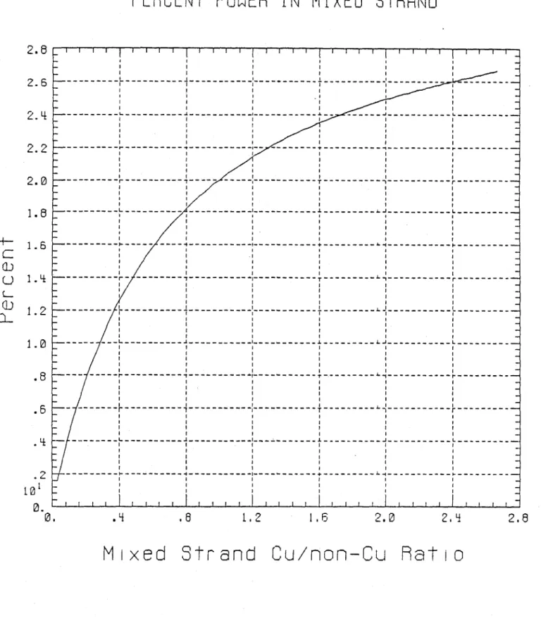
" The percentage of the total joule heating that occurs in the mixed strand is
P.
R-2
2Pc + P,
3R
Graphs of these two expressions are included as figures following the text. Both are plotted against R, and also against r. From them one can see, as an example, that if a triplet were to be made of two copper strands and one mixed strand with a copper to noncopper ratio, r, of about 1.7:1, the overall ratio R would be about 7:1. At the onset
of current sharing, joule heating in the mixed strand would account for about 24% of the total, anbd in each copper strand, about 38% of the total. That is, about 50% more heat is produced in each copper strand than in the mixed strand.
The issue of greatest potential impact on cable design is whether this extent of joule heating partitioning would yield different operating characteristics during transient in-stabilities and/or propagating normal zone events, compared to the characteristics of a conventional homogeneous cable. If the temperature of the mixed strand and of the cop-per strands were appreciably different, the characteristics would be different, due solely to the variation of resistivity with temperature. For the following reasons, this is probably
not the case:
e One of the intitial assumptions was that the strands of the triplet are tightly enough twisted that they are in good electrical contact along their entire length. To be consistent, the assumption should also be made that they are in good thermal contact as well. The tendency is, then, toward temperature equalization.
e Helium turbulence induced by rapid local heat transfer would tend to equalize the temperature of all strands.
* If the greater rate of heating - and a factor of 1.5 is not really very much greater - in the copper strands begins to raise their temperature above that of the mixed strand, then the division of current that was derived above would no longer hold; some of the shared current would return to the copper in the mixed strand. This would tend to increase the rate of heating therein which, in turn, would tend to restore the equality of temperature and hence, the initial current partitioning.
This allows us to conclude that the nonhomogeneous triplet conductor is a reasonable test choice, and verification will allow development of a new conductor with potential significant economic advatages.
4.1.3 Predictive Analysis
Analysis is under way to predict the performance of the subsize conductors in the test configuration described below. This analysis addresses problems of transient stabil-ity in which sudden energy inputs in the range of 100 microseconds to 100 milliseconds are considered, and steady-state stability where energy inputs over long time periods are considered ( 1 s to steady state). The maximum amount of energy that can be input into the conductor without causing a quench will be measured and energy margins (mJ/cm3)
will be compared with predictions. To this end, a computer program that examines heat rise in conductor and liquid helium when a specific amount of energy is introduced into the conductor has been modified and upgraded. Both the amplitude and duration of the heating pulse can now be changed. The program has now been expanded to search auto-matically for the energy margin at any desired operating curreny (Ip) in the conductor at any given background field condition. Energy margin vs
Ip
has been calculated andplotted for several background field values for both subscale conductors. In these cases the energy has been delivered to the superconductor. While this is the case for conductor used in fusion systems where the principal energy sources are from conductor AC and/or hysteretic losses, this is not a realistic assumption for MHD magnets wound of ICCS. It is most probable that energy will be introduced through the ICCS conduit from frictional heating. Because of this difference it has been necessary to develop a new set of models and analytical tools appropriate to the ICCS MHD magnet case. Therefore, additional analysis is planned to examine heat rise in conductor and liquid helium when the energy perturbation is introduced through the sheath.
Similarly, maximum hot-spot temperatures and pressures will be measured and com-pared.
The analysis will consider the differences in both electrical and thermal contact resis-tances between the two configurations; the slight differences in overall copper-to-superconductor ratios in the two triplet configurations and also the inherently different filament sizes in different strands (or strand in the case of the 2 and 1 cable) and therefore, different critical currents in the superconductor.
4.2 Subscale Tests
4.2.1 Test Rig and Test Objectives
The two test-coil assemblies wound from the Type A and Type B subscale conductors will be mounted on support probes for insertion into an existing LHe-cooled, LN2-shielded
Dewar. Special precautions must be taken to provide structural support of the coil assem-bly due to large eccentric forces generated. Both ends of each conductor will be terminated for low-loss connection to 2,000 A current leads as well as helium plumbing connectors as shown in figures 6 and 7.
Test operations will be carried out as follows:
The test coil is first mounted on its probe and then inserted into a 150 mm OD Dewar. The Dewar is then inserted into the background field coil at the Francis Bitter National Magnet Laboratory. This is an 8 T peak on-axis solenoid of Bitter-plate construction. After appropriate cooldown and Dewar backfill with liquid helium, the background field is raised to the desired field level. Field levels of interest will range between 4 and 8 tesla. Helium pressure in the ICCS conductor itself will be maintained at 2.5 to 3 atm - that is, in a supercritical single phase state. Cooldown without mass flow between test runs is assured since the ICCS conductor is immersed in a liquid helium bath.
The objective is to determine the energy margin,
Q,
of an ICCS conductor operating at a given field, B, as well as at a given current level, Ip. The transient energy pulse is delivered to the conductor inductively by means of a pulse coil set shown in figures 6 and 7. In order to energize the pulse coil, a capacitor must be charged to some predetermined level such as 100 V. The test run takes place with a discharge of the capacitor into the pulse coil. This will be done using a half-cycle (single) pulse lasting 100 ms. The amount of energy which is inductively coupled into the test coil is known from extensive calibration tests. Voltage taps across the test conductor will indicate whether or not the conductor recovers or goes normal (quenches). Several discharge runs must be performed to narrow the range between recovery and nonrecovery. In these tests it is expected that the transient stability of the Type A ICCS test conductor will be higher than that of Type B, because all strands have copper in intimate contact with the superconductor.Similar tests will be performed in which the conductor is heated externally. Here the heater will be wound in such a way to simulate frictional heating from conductor-to-conductor motion. Heating will be done of both short sections of about 30 cm length and long, meter or more sections. Under these most probable heating conditions the energy margin of the "two-and-one" triplet should be comparable to that of the triplet in which all strands are multifilamentary superconductors because the total enthalpy of the composite should be available to stabilize against such thermal perturbations.
Separate ramp tests, in which the current will be ramped from zero to maximum current at different, ever increasing rates, will also be performed. The objective of this test will be to determine whether or not there in any significant Lorentz compaction heating during magnet energization.
In the case of protection, it it assumed that the conductor has ceased to be super-conducting. Current must transfer to the now less-resistive satbilizing copper located in both the multifilamentary strand and in the pure copper strands. Since adequate volt-age is available under these conditions, it is hypothesized that the all-copper starnds will participate fully in the protection process.
To protect the ICCS from overheating, it must be provided with the following: 1. An adequate amount and quality of stabilizing copper to minimize heating during
sutdown. The quality of the copper is defined in terms of thr effective Residual
Resistivity Ratio, RRR. RRR = 100 is readily available.
2. A "quench detection" system designed to detect the existence of a normal zone anywhere within the coil winding.
4. A shunt-connected dump resistor to absorb the magnetic stored energy and to provide an adequately short current-decay time constant, to limit the ICCS hot-spot temperature to a safe value.
The test program will determine these requirements. 4.2.2 Full-scale Test
The proposed baseline design assumes a 486-strand conductor encased in a stainless-steel sheath having overall dimensions of approximately 2.5 cm square. Approximately 15 meters of this conductor will be wound into a coil in a configuration closely duplicating the actual operating environment of a large-scale MHD magnet. This coil will be tested while monitoring its performance with respect to stability, quench propagation and pressure dynamics.
The final test performance analysis will include definition of the program, time and cost to fully develop the manufacturing technology required for minimum-risk construction of a large-scale MHD magnet.
5.0
References
1. Quarterly Progress Report, Oct. 1, 1984 to Dec. 31, 1984, Develop and Test an ICCS
for Large Scale MHD Magnets, MIT, March 1985 DOE/PC-70512-2.
2. Technical Progress Report, period from Jan. 1, 1985 to June 30, 1985, Develop and
Test an ICCS for Large Scale MHD Magnets, MIT, November 1985,
DOE/PC-70512-4.
3. Analysis Report, Develop and Test an Internally Cooled Cabled Superconductor
(ICCS) for Large Scale MHD Magnets, MIT, January 1986, DOE/PC-70512-5.
4. C.J. Heyne, D.T. Hackworth, S.K. Singh, Y.L. Young, Westinghouse Design of a
Forced Flow Nb
3Sn Test Coil for the Large Coil Program, and references therein,
Eighth Symposium on Engineering Problems in Fusion Research, pp 1148-1153, 1979.
5. P. A. Materna, Design Considerations for Forced-flow Superconductors in Toroidal
Field Coils, Tenth Symposium on Engineering Problems in Fusion Research, pp
1741-1746, 1983.
Cu/non-Cu HRTIO LOOKUP CHRPT
1. - -- - - - - -- - - - - - -- - - - - - -- - - - - -- - - - - - - T -----0.
6------.9
0. .5 1. 1.52 0 .. mi e s.ran r atiFi.1-T i sacneintrpeetto
feuto () h ierrltosi
bewe th ovrl coprocpe aiR n hemxdsrn oprocpe
ratio, r
POWER~ HRTIO,
Pc/Pm
3. 5 3.0 2.5 2.0 1.151.0
.5 I0 10.
- - - -- ---- -- - --- ---- - -- -- -- ---- - -- - - -- --- -- --- --- --- -- --- - --- --- --- --- --- --- --- -- --- - - - - - -- - - -- -- ---- --- --- ---- - -- ---- - - - J --- - - - - -- - - -- -- -.610
1
.8
1.0
Overal
Cu/mon-Cu Ratio
Fig. 2 - The ratio of joule heating in each copper strand to tha~t in the mixed strand, plotted as a function of the cable's overall copper: noncopper ratio,
R.
0U
-POWER RRTIO, Pc/Pm
.
.6
[. 2
1.6
2.02.4L
2.6Mixed Strand Cu/mom-Cu Ratio
Fig. 3
- This is the same data as wa~s presented in the previous figure, hut here it is plotted as a function of the copper: noncopper ratio in the mixed strand, r.3.5
3.02.5
2.0 1.5U
a I I I I I I I I I[
I a I a I a i I I a I I I a I a I a I I I I I I I I I I a I a I a I I I I I I I I I aj
I I I I.---4---L. S a I I a I a I I a a I I I I I I I a a a a a I a I a I a a I I a a I I a a a aK
I I I I I I a I I a a ---a I I I I a I I a a I I I I I a I I a a I a a a a a I I I I I I I I I I a I I I a a a I I I I a i a a a a a---+---.4---. a I I a a a a a a I I a a a a a a a I I a a a a a a a a a a a I I a a a a a -a a a a a a a I a a a -a a a a a a a a a a a a I a a a I I a a a a a a a i a a a I -a a a a a a a I I a a a a i a a I I I a a a a -a a I a a a a I a I a I I I I I -I I I a a a ---a a I a a a I I I a a a -a I a a a I I a a a a I I a a I a a a a a I I a a a a -. I I I a a a a a a a a -a a a a a a I I I a a Ii a a I ~a a a a a a aI
a1.0
.5 0.6. 4
.6
18
OVEROLL Cu/non-Cu RRT10
Fig. 4 - The percentage of the total joule heating that takes place in the mixed strand, plotted as a function of the cable's overall copper: noncop per ratio, R.
2. B 2.6 2.4 2.2 2.0 1.8 1.6 1.4 1.2 1.0 .8 .6 .4 .2 to I 0.
- ---
---
--- --- --- --- --- --- ------ --- --- --- --- ---
--- -
- --- -
--- --- ---
--- j-*
--- i
---
---
---
--- ---
--- ---
---- --- ----
--- ---
---
--- - - - - - - - -- --C--)
ry-LLJ
n
101
1.0
PERCENT POWER IN MIXED STRAND
.4
.8
1.2
1.6
2.0
2. q
Mixed Strand Cu/non-Cu 9atio
Fig. 5 The percentage of the total. j( ultc licatirig that takcs place in the mixed strand, plotted as a function of the copper: noncopper ratio in the mixed stra.nd, r.
2.8
2.8 2.6 2.4 2.2 2.0 1.8 1.6 1.4 1.2 1.0 .2 to 0. --- --- --- L --- --- ---L--- --- ---
- - -- - - - - - - - --- - - - - -- - - -- - - -----
--- --- - -- - - - -- - - -- - - -- - - - - --- - - - -I r - --- T - - - - --- L --- --- --- IL --- --- L --- ---- --- --- --- ---I --- r - --- 7 --- --- T --- --- r ---L - - - - - - - - -J - - - - -L - - - - - - - -L - - - --1 - - - -L - - - ---- --- ---
--- ---
---
-)
---
r
---
--- --- --- L
--- --- ---
---
L
---I f ---I ---I
I I
UU
n
(@
Digital
Oscilloscope
Pre-Amplfler s
Attenuator
-10kA
Supply
Pulse
Power
Supply
Pulse Coils
I-C
Pressure Tran su& Ascfv coi
Eitter
4
C'il
Fig. 6 - Schematic of the instrumentation and experimental set-up.
P
P Flow
Check
Valve
He gas
LN
2
Heat
Exchanger
-*Va cuum
Pump
Relief
Valve
Shut
off
Vaive
Pressure
Transducer
-
Curren
Leads
LHe
XL
.
Codl
Coils
ruis.
Fig. 7 - Schematic of the helium flow circuit.
=
'p