A Probabilistic and Timed Verification Approach of
SysML State Machine Diagram
Abdelhakim Baouya
Saad Dahleb UniversityCS Department Blida, Algeria [email protected]
Djamal Bennouar
University of Bouira CS Department Bouira, Algeria [email protected]Otmane Ait Mohamed
Concordia University ECE Department Montreal, Canada [email protected]Samir Ouchani
University of Luxembourg ECE Department Luxembourg [email protected]Abstract—Timed-constrained and probabilistic verification approaches gain a great importance in system behavior valida-tion. They enable the evaluation of system behavior according to the design requirements and ensure their correctness before any implementation. In this paper, we propose a probabilistic and timed verification framework of State Machine diagrams extended with time and probability features. The approach consists on mapping the extended State Machine diagram to its equivalent probabilistic timed automata that is expressed in PRISM language. To check the functional correctness of the system under test, the properties are expressed in PCTL temporal logic. We demonstrate the approach efficiency by analyzing performability properties on a Automatic Teller Machine (ATM) case study.
Keywords—State Machine Diagram, MARTE, Probabilistic Timed Automata, Model Checking, PCTL.
I. INTRODUCTION
Constraints on system design in terms of functionality, performance, availability, reliability and time to market are becoming more stringent. Therefore, the design and imple-mentation of successful systems, represent the prime concerns of systems engineering (SE) but reveals several challenges[9]. Indeed, from one side the systems are becoming increasingly complex, in the other side the market pressure for rapid development of these systems makes the task of their designs a challenge. Thus, the evaluation and the correctness of systems at early stage of design reduce the design cost such as maintenance time and effort. Recently, automated verification techniques gain more popularity and especially to cope with errors that can occur when the system is running. The quan-titative approach using model checking gives more accurate observations on systems that exhibit real time characteristics., as the avionic and automotive systems operating under timing constrains. The UPPAAL model checker [4] seems to be suitable to represent a timed automaton but more real time systems exhibits a probabilistic behavior like system failure, communication error that can be managed by probabilistic model checking [3].
Model checking is an automated technique that, given a finite-state model of a system and a formal property, automat-ically checks whether this property holds or not for that model. The model checking focuses on qualitative or quantitative properties [3]. The qualitative properties assert that certain event will happen surely or not. The quantitative properties are based on the probability or expectation of certain events (e.g.
the probability of the system failure in the next 5 times units is 0.85). Probabilistic model checking is an effective technique to probabilistically verify the satisfiability of a given property. In our paper we use PRISM model checker [15] for probability and time verification.
In System Engineering, System Modeling Language (SysML) is a standard language [1] used for specification, analysis, design and verification of a broad range of com-plex systems (e.g. Hardware, software, information workflow). SysML reuses a subset of UML2 artifacts (Unified Model-ing Language) and provides additional extensions to specify requirements such as probability. Behavioral specification is achieved in SysML using three diagrams: State Machine, Communication and Activity Diagram. State Machine diagram is particularly studied in our paper.
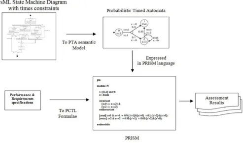
The execution time of behavior in SysML depends gen-erally on resource availability. This may result in a variation of total time completion. Thus, if an state behavior terminates within a bounded time interval then, a probability distribution for terminating the state behavior can be established with respect to the execution time interval. This paper proposes a probabilistic and timed verification of SysML state machine diagrams that are guarded with time constraints. We use MARTE time annotation on the top of state machine nodes that specifies the estimation of time duration of an action (behavior) execution. Moreover, the time annotation are only specified for states nodes in the form of time interval I=]min, max[, where min, max are integer values. Time value min represents the earliest value for execution completion of the corresponding state’s behavior and time value max is the latest. Furthermore, the state’s time duration can be omitted if the execution time is negligible. The semantic interpretation of state machine diagram is encoded into the input language of a probabilistic symbolic model checker (PRISM) to produce the satisfiability of the PCTL property on state machine diagram. For the verification efficiency, the constructed models can be either multi-terminal binary decision diagram (MTBDD), sparse matrices, as well as a hybrid of these two. In addition, PRISM supports the reward operator that can be used to specify a wide range of measures of interest (e.g. The total energy consumed by the system, the time that the system is operational). A comprehensive comparative study of proba-bilistic model checkers can be found in [18]. The kernel of the framework is based on transforming the state machine diagram to its equivalent Probabilistic Timed Automata (PTA)
Figure 1: Verification framework for SysML state machine diagram
expressed in PRISM language. Finally, PRISM model checker produces the satisfiability results of PCTL properties on the mapped model. These properties depend on the functional requirements and performance specifications of the system. The proposed framework is depicted in Fig.1.
The remainder of this paper is structured as follows: Section II discusses the related work. Section III and IV describe and formalize SysML state machine diagrams and PRISM model, respectively. Section V provides a mapping mechanism of state machine diagrams into PRISM. Section VI illustrates the application of our framework on a case study. Section VII draws conclusions and lays out the future work.
II. RELATED WORK
In this section, we present the recent works related to the verification of behavioral models then we compare them with our proposed approach.
Doligalski and Adamski[6] propose a verification and sim-ulation of UML State Machine. For this purpose, two mapping mechanisms are defined. The first consists on mapping the original model to Petri network for verification according the requirements. When the requirements are satisfied, the second mapping occurs to generate VHDL or Verilog description for simulation. The data on each transition is considered as a trigger for a new state but probability and time verification are not considered. Huang et al.[11] propose a verification of SysML State Machine Diagram by extending the model with MARTE [17] to express the execution time. The tool has as input the State Machine Diagram and as output Timed automata expressed in UPPAAL syntax [4]. UPPAAL uses CTL (Computational Tree Logic) properties to check if the model is satisfied with liveness and safety properties. Ouchani et al. [19] propose a verification framework of SysML activity diagram. The authors address a subset of SysML activity diagram artifacts with control flow. The different artifacts have been formalized and a verification algorithm has been proposed for mapping these artifacts to PRISM language. The transformation result is a probabilistic automata to be
checked by PRISM. Timing verification is not considered in this paper. Jarraya et al. [12] propose a probabilistic verifi-cation of SysML activity diagram where the execution time of actions are formalized as constraints (i.e. A note artifact in SysML Activity diagram). The diagram is translated to its corresponding DTMC and use PRISM model checker for performance evaluation using PCTL. The approach is restricted on a subset of SysML activity diagram constructs with control flow (data flow is missing). Kaliappan et al. [13] propose a verification approach for system work-flow especially in communication protocol. The approach takes as input three UML diagrams: state machine diagram, activity diagram and sequence diagram. state machine diagram or activity diagram is converted into PROMELA code as a protocol model and its properties are derived from the sequence diagram as Linear Temporal Logic (LTL). Lasnier et al. [16] develop a framework for automatic generation of embedded real time applications in C/C++/ADA. The input is AADL language (Architecture Anal-ysis and design Language) with typed software components (e.g. threads, data) and hardware components (e.g. processor, bus, memory). In addition, the design model is enriched with time execution properties (e.g. computation time, priority, deadline and scheduling algorithms) . For timing estimation and optimization, a scheduling tool is used based on software components timing constraints. After time optimization, the framework generates C/C++/ADA code that can be simulated. Pajic et al.[20] develop a framework for verification and generation of real time applications either in C/C++code for software or in Hardware description language (HDL) like VHDL or Verilog. The focus of the work is a development of model translation tool UPPAAL[4] to Stateflow (UPP2SF). The checked UPPAAL model is translated to Stateflow using Simulink which provides full support for C/C++, VHDL and Verilog code generation for simulation purpose.Ando et al. [2] propose a verification approach of SysML state machine dia-gram. The diagrams are translated to communication sequential process description (CSP) and they apply the PAT[21] model checker to check the CSP models against the LTL properties. The paper proposes a mapping rules of different state machine
artifacts. However, time and probability are not addressed in the paper. Knorreck et al. [14] develop a framework for timing verification of real time system specification incorporating a combined UML, SysML diagrams and customized profile. Each block diagram and its state machines are converted to a corresponding automata in UPPAAL syntax. The properties are derived from parametric diagram as Computational Tree Logic (CTL). Elmansouri et al. [7] propose a mapping approach of UML activity diagram to CSP by using a graph transformation called ATOM tool. For this purpose, the authors propose a meta-model for activity diagram and graph grammars that performs automatically the transformation of activity diagram. Probability and time are not addressed in this paper.
Compared to the existing few works, our contribution improves the verification of SysML State Machine diagram by extending State Machine with elements of UML MARTE profile to support time and probability. In addition, we use PRISM model checker to verify the satisfiability of different performance requirements expressed in PCTL properties.
III. STATEMACHINEDIAGRAM
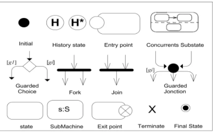
SysML State Machine diagram is a graph-based diagram where states nodes are connected by edges(transition)[8]. Fig-ure 2 shows the set of interesting artifacts used for verification in our framework. The behavior of a state machine is specified by a set of regions, each of which defines its own set of states. The states in region are exclusive; that is, when the region is active, exactly one of its substates is active. A region starts executing when it initial pseudostate becomes active. When a state is activated, an (optional) entry behavior is executed. Similarly on exit, an optional exit behavior is executed. While in a state, a state machine can execute a do behavior (Activity, State machine, Interaction, Opaque Behavior). A region also has a final pseudostate that, when active, signifies that the region has completed. Change of state is effected by transitions that connect a source state to a target state. Transitions are defined by triggers, guards, and effects. The trigger indicates an event that can cause a transition from the source state, the guard is evaluated in order to test whether the transition is valid, and the effect is a behavior executed once the transition is triggered. Triggers may be based on a variety of events such as the expiration of a timer, or the receipt of a signal. In addition to initial and final pseudostate, control nodes supports a junction, choice, join, fork, terminate and history pseudostate node. A junction nodes are used to chain together multiple transitions. A single junction can have one or more incoming, and one or more outgoing transitions, a guard can be applied to each transition. A junction which splits an incoming transition into multiple outgoing transitions realizes a static conditional branch, as opposed to a choice pseudo-state which realizes a dynamic conditional branch. Initially, when a state machine diagram is invoked, its initial node is activated. Then, the activation of any other node (states or pseudostates) depends only on the deactivation of its predecessor node and the guard satisfaction of its input edge.
A. Probability and Time Expression using the elements of SysML/MARTE
In this sub section, we try to depict the existing ways to express the time in SysML state machine diagram. MARTE is
Figure 2: A subset of State machine diagram artifacts
a UML profile standardized by OMG [17] aims to replace the UML profile SPT (Profile for Schedulability, Performance and Time). MARTE was defined to make quantitative predictions regarding real-time and embedded features of systems taking into account both hardware and software characteristics. The core concepts are design and analysis parts. The design parts are used to model real time embedded systems. On the other hand, the analysis parts provide facilities to support the resources analysis such as probability, execution time, energy and memory usage. In our paper, we use probability and execu-tion time for quantitative verificaexecu-tion. Figure 3 illustrates how the probability value is specified on the outgoing edges of the choice nodes testing their corresponding guards. In addition, the transition leaving choice nodes are annotated with the << GaStep >> stereotype, specifying the probability (prob) of traversing one of the conditional branches. The time is specified by applying the stereotype << resourceU sage >> with element execTime to specify the maximum and the minimum value of the time duration written as (value, unit, max). The state ”TurnOn” requires exactly 2 units of time to terminate; State ”AutoFocus” terminates within the interval ]1,2[. The state ”TakePicture” execution time is negligible. To model probabilistic systems, the probabilities are assigned to edges emanating from decision nodes where the assigned values should sum up to 1. For instance, the choice node testing the guard ”memFull”has the following semantic interpretation: the probability is equal to 0.2 that the outcome of the choice node will be (memFull=true) and the corresponding edge traversed.
IV. PRISM MODELCHECKER
In this section, our formalization focus on probabilistic timed automata (PTA) that extends the standard probabilistic automata (PA) considered as appropriate semantic model for SysML Activity Diagram [19]. The PRISM model checker supports the PTA with the ability to model real-time behavior by adding real-valued clocks (i.e. clocks variable) which increases with time and can be reset (i.e. updated).
A Timed Probabilistic System (TPS) that represents a PRISM program (P) is composed of a set of ”m” modules (m > 0). The state of each module is defined by the evaluation of its local variables VL. The global state of the system is
Figure 3: Digital camera state machine diagrams [12]
∪ VG. The behavior of each module is described as a set of
statements in the form of: [act]guard → p1 : u1.. + pn : un
Where act is an (optional)action labeling the command, the guard is a predicate consists of boolean, integer and clock variables and propositional logic operators , p is a probability. The update u is a set of evaluated variables expressed as conjunction of assignments (Vj0 = valj)&..&(Vk0 = valk)
where Vj ∈ VL U VG and valj are values evaluated via
expressions denoted by ”eval” eval: V → R U {T rue, F alse}. The formal definition of a command is given in Definition 1. Definition 1
A PRISM command is a tuple c = < a, g, u >. • ”act” is an action label.
• ”guard” is a predicate over V.
• ”u” = {(pi, ui)} ∃m > 1, i < m, 0 < pi <
1,Pm
i pi= 1 and u = {(v, eval(v)) : v ∈ Vl}.
The set of commands are associated with modules that are parts of a system and it definition is given in Definition 2.
Definition 2
A PRISM module is tuple M = < Vl, Il, Inv, C>, where:
• Vlis a set of local variable associated with a module,
• Inv is a time constraint of the form vl on d\ on∈ {≤, ≥} and d ∈ N,
• Il is the initial value of Vl.
• C= {ci, 0 < i ≤ k}is a set of commands that define
the module behavior.
To describe the composition between different modules, PRISM uses CSP communication sequential process operators [10] such as Synchronization, Interleaving, Parallel Interface, Hiding and Renaming. Definition 3 provides a formal defini-tion of PRISM system.
Definition 3
A PRISM system is tuple P = <V, Ig, exp, M, CSPexp>,
• V = Vg`m(i=1)Vliis the union of a set local and global
variables.
• Ig is initial values of global variables.
• exp is a set of global logic operators. • M is a set of modules composing a System. • CSPexp is CSP algebraic expression.
The structure of our temporal logic supported by PRISM model checker is expressed by the following BNF grammar: A. Property specification for PTAs
The syntax of our logic is given by the following grammar: ϕ :: =true | ap |ϕ ∧ ϕ |¬ϕ | P./p[ψ] | R./q[ρ],
ψ :: = ϕ ∪≤kϕ | ϕ ∪ ϕ , ρ :: = I=k | C≤k | F ϕ
Where ”ap” is an atomic proposition, P is a probabilistic operator and R is a reward. Operator P./p[ψ] means that the
probability of path formula ψ being true always satisfies the bound on p, p ∈ [0, 1]. Two paths formulas are included bound until ϕ1 ∪ ϕ2 and time-bound until ϕ1 ∪≤kϕ2 . Bound until means that a state satisfying ϕ2 is eventually reached and that, at every instant prior to that, ϕ1 is satisfied. The time-bounded variant has the same meaning, where the occurrence of ϕ2 occur within time k. R./q[ρ] means that the expected
value of reward function ρ meets the bound ./ q, q ∈ Q. ”on”∈ <, ≤, >, ≥. ”∧” represents the conjunction operator and ”¬ ” is the negation operator. The reward operator I=krefers to the
reward of the current state at time instant k, C≤krefers to the total reward accumulated up until time point k, and F ϕ to the total reward accumulated until a state satisfying ϕ is reached, e.g:
- Rtime
max=?[F TurnOff] : what is the maximum expected
time to take a picture and turn off ?.
V. MAPPINGSTATEMACHINEDIAGRAMS INTOPRISM
In this section, we propose the translations rules of state machine diagram artifacts to their equivalent PRISM com-mands.
A. Start State Machine
Figure 4: Start State Machine
A non composite states (Fig.4, Listing.1) are represented by a Boolean variable set to false except the initial state. The clock variable is reset to 0 when the triggered state contains a time interval.
1 start : bool init true;
2 TurnOn :bool init false;
3 login : [0..5] init 0;
4 ...
5 [start] start→(initializing’=true)&(start’=false);
6 [initializing] initializing →(login’=0);
7 [do] initializing & login=0 →(login’=login+1);
8 [exit]initializing & login>0 →(login’=login-1)
9 &(initializing’=false);
Listing 1: Start State Machine
B. Setting the Invariant (maximum execution time)
Figure 5: Time invariant
For each non composite state (Fig.5, Listing.2) having an execution time interval, we generate its specific clocks variable. The maximum value of the generated clock is set within invariant clause to impose the different values of clock variable.
1 invariant (TurnOn=true ⇒ x ≤2) endinvariant
Listing 2: State Invariant
C. State transition
Figure 6: State transition
The transition has the form: trigger[guard]/behavior (Fig.6, Listing.3), the trigger specifies events that may induce state transition, the guard is a transition condition and behavior may be a data update. In the case when the trigger is time event either that a given time interval has passed since the current state was entered (after), or that a given instant of time has been reached (at) the resulting command guard that corresponds to the minimal time transition. We support data update in our paper as a resulting behavior.
D. Junction pseudostate
The junction pseudostate (Fig.7, Listing.4) splits an incom-ing transition into multiple outgoincom-ing transitions accordincom-ing the static conditional branch. A junction pseudostate is like an initial pseudostate, as a filled circle.
1 [loggedOn] loggedOn & loggedIn=1 → (loggedOff’=true)
2 &( loggedOn’=false)&( loggedIn’= loggedIn-1);
3 [loggedOff] loggedOff → ( l o g g e d O n =true)
4 &( loggedOff’=false)&( loggedIn’= loggedIn+1);
Listing 3: State transition
Figure 7: Junction pseudostate
1 [N1] N1 → (Junction11’=true)&( N1’=false);
2 [N2] N2 → (Junction12’=true)&( N2’=false);
3 [Junction11] Junction11 & (g1=true) →
4 (N3’=true)&( Junction11’=false);
5 [Junction12] Junction12 & (g2=true) →
6 (N4’=true)&( Junction12’=false);
Listing 4: Junction pseudostate
Figure 8: Choice pseudostate
1 [N1] N1 → (choice’=true)&(N1’=false);
2 [choice] choice → p1: (lg1’=true)&( choice’=false)
3 + p2: (lg2’=true)&( choice’=false);
4 [lg1] lg1 & g1→ (lg1’=false)&( N2’=true); 5 [lg2] lg2 & g2→ (lg2’=false)&( N3’=true);
Listing 5: Choice pseudostate
E. Choice pseudostate
A choice node (Fig.8, Listing.5) has multiple incoming transitions and outgoing transitions. The output flow is typ-ically established by placing mutually exclusive guards on all outgoing flows and offering the token to the flow whose guard expression is satisfied. We add probability feature at the outgoing edge. Each token can only traverse one edge, with the specified probability.
Figure 9: Fork pseudostate
F. Fork pseudostate
A fork node (Fig.9, Listing.6) has a single incoming transition and many outgoing transitions. When an incoming transition is taken to the fork pseudostate, all of the outgoing transitions are taken.
1 [fork] fork → (N1’= true)&(N2’= true)&(fork’= false);
Listing 6: Fork pseudostate
G. Join pseudostate
Figure 10: Join pseudostate
The join node (Fig.10, Listing.7) represents a special case, it has to wait for a locus of control on each incoming edge in order to be traversed. we are obliged to decompose the join node in a set of nodes to realize a synchronization.
1 [join1] N1 → (join1’= true)&(N1’= false) ;
2 [join2] N2 → (join2’= true)&(N2’= false) ;
3 [join] join1 & join2 → (join’= true)&(join2’= false)
4 &(join1’= false);
Listing 7: Join pseudostate
H. Terminate pseudostate
Figure 11: Terminate pseudostate
1 [Terminate] N → (N’= false) ;
Listing 8: Terminate pseudostate
If a terminate pseudostate (Fig.11, Listing.8) is reached, then the behavior of the state machine terminates. The minimal clock value indicates the condition that enables the transition.
I. Final State
Figure 12: Final State
The final state (Fig.12, Listing.9) indicates that a region has completed execution and all existing states variables will be set to false.
1 [End] N → (N’= false) & ... & (Ni’= false);
Listing 9: Final State
VI. IMPLEMENTATION AND EXPERIMENTAL RESULTS
In the following, we present a case study [5] related to a SysML based design describing an automated teller machine (ATM). We perform the verification of this design with re-spect to predefined properties. Listing.10 is the corresponding generated code.
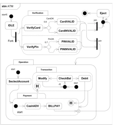
The ATM interacts with a potential customer (user) via a specific interface and communicates with the bank over an appropriate communication link. A user that requests a service from the ATM has to insert an ATM card and enter a personal identification number (PIN). Both pieces of information (the card number and the PIN) need to be sent to the bank for validation. If the credentials of the customer are not valid, the card will be ejected. Otherwise, the customer will be able to carry out one or more transactions (e.g., cash advance or bill payment). The card will be retained in the ATM machine during the customers interaction until the customer wishes for no further service. Fig.13 shows the SysML state machine diagram of the ATM system.
ATM state machine encloses four substates: IDLE, Veri-fication, Eject, and Operation. The IDLE state, wherein the system waits for a potential ATM user, is the default initial substate of the top state. The Verification state represents the verification of the cards validness and authorization. Verifiy-Card and VerifyPin substates have interval time ]3s,5s[,]4s,5s[ respectively (s for seconds). The probability to get pin and card validated is 0.7 and 0.8, respectively. The Eject state depicts the phase of termination of the users transaction. The Operation state is a composite state that includes the states that capture several functions related to banking operations. These are the Selectaccount, Payment, and Transaction.
When the state Selectaccount is active, and the user selects an account, the next transition is enabled and the state Payment is entered. The Payment state has two substates, respectively, for cash advancing and bill payment. It represents a two-item menu. Finally, the Transaction state captures the transaction phase and includes three substates: CheckBal for checking the balance, Modify for modifying the amount, if necessary, and Debit for debiting the account.
Each one of the Payment and Transaction states contains a shallow history pseudostate. If a transition targeting a shallow
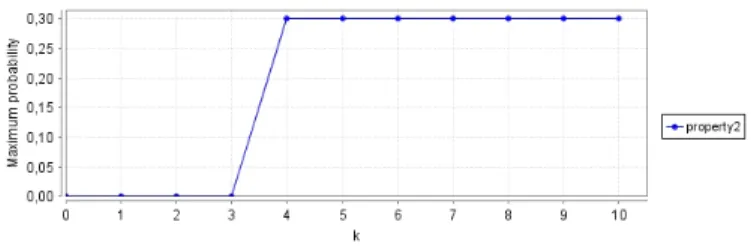
Figure 14: Property1
history pseudostate is fired, the most recently active substate in the composite state containing the history connector is activated.
In order to check the correctness of the ATM system, we propose to verify two functional requirements. They are expressed in PCTL as follows:
1. The maximum probability value to get the card and pin validated after k time units.
P max =?[F≤k(CardV ALID & P inV ALID )] (1) 2. The maximum probability value that the modification occurs during the Bill Payment after k=5 time units.
P max =?[F≤k(BillP AY & M odif y))] (2) The maximum probability value for the modification occurs during the Bill payment is equal to 0.3 when k equal to 5 (time units). The verification results of the first property are shown in Fig 14. After 4 time units (seconds), the verification results converge to 0.3 .
1 pta
2 module ATM
3 start : bool init true;IDLE :bool init false;
4 Join11 :bool init false;Join12 :bool init false;
5 Join1 :bool init false;
6 M11 :bool init false;M12 :bool init false;
7 M13 :bool init false;M1 :bool init false;
8 Eject :bool init false;Final : bool init false;
9 [start] start -> (start’=false)&(IDLE’=true);
10 [IDLE] IDLE-> (IDLE’=false)& (Fork’=true);
11 [Fork] Fork-> (Fork’=false);
12 [exit11] (Join11=false =>true) ->(Join11’=true);
13 [exit12] (M11=false =>true) ->(M11’=true);
14 [exit21] (Join12=false =>true) ->(Join12’=true);
15 [exit22] (M12=false =>true) ->(M12’=true);
16 [join] Join11 & Join12 ->(Join1’=true) & (Join11’=false)
17 & (Join12’=false);
18 [M11] M11 -> (Eject’=true);
19 [M12] M12 -> (Eject’=true);
20 [M13] M13 -> (Eject’=true);
21 [fin] (Eject=false =>true) -> (Eject’=true);
22 [final] Eject -> (Eject’=false) & (IDLE’=false)
23 &(Join11’=false)&(M11’=false) &(Join12’=false)&
24 (M12’=false)&(Join1’=false) ;
25 [Join1] Join1 -> (Join1’=false);
26 endmodule
27
28 module CheckCard
29 start2 : bool init false;VerifyCard : bool init false;
30 C1 : bool init false;CardOK : bool init false;
31 NotCardOK : bool init false;CardVALID : bool init false;
32 CardNOTVALID : bool init false; x1: clock;
33
34 invariant (VerifyCard=true =>x1<=5) endinvariant
35 [Fork] (VerifyCard=false =>true)- (VerifyCard’=true);
36 [VerifyCard] VerifyCard & x1>= 3-> (VerifyCard’=false)
37 &(C1’=true);
Figure 13: ATM state machine diagram
39 +0.4:(C1’=false)& (NotCardOK’=true);
40 [CardOK]CardOK-> (CardOK’=false) & (CardVALID’=true);
41 [NotCardOK]NotCardOK-> (NotCardOK’=false)
42 & (CardNOTVALID’=true);
43 [exit11] CardVALID ->(CardVALID’=false);
44 [exit12] CardNOTVALID ->(CardNOTVALID’=false);
45 endmodule
46
47 module CheckPin
48 start3 : bool init false;VerifyPIN : bool init false;
49 C2 : bool init false;PinOK : bool init false;
50 NotPinOK : bool init false;PinVALID : bool init false;
51 PinNOTVALID : bool init false; x2: clock;
52
53 invariant (VerifyPIN=true =>x2<=5) endinvariant
54 [Fork](VerifyPIN=false =>true)->(VerifyPIN’=true);
55 [VerifyPin]VerifyPIN & x2 >=4->(VerifyPIN’=false)&(C2’=true);
56 [C2] C2 -> 0.5:(C2’=false)& (PinOK’=true)+
57 0.5:(C2’=false)& (NotPinOK’=true);
58 [PinOK]PinOK-> (PinOK’=false) & (PinVALID’=true);
59 [NotPinOK]NotPinOK-> (NotPinOK’=false)&(PinNOTVALID’=true);
60 [exit21] PinVALID ->(PinVALID’=false);
61 [exit22] PinNOTVALID ->(PinNOTVALID’=false);
62 endmodule
63
64 module Operation
65 start4 : bool init false;SelectAccount: bool init false;
66 History1: bool init false;History2: bool init false;
67 fin :bool init false;
68 [Join1] (start4=false =>true) -> (start4’=true);
69 [start4] start4 -> (start4’=false)& (SelectAccount’=true);
70 [SelectAccount] SelectAccount -> (SelectAccount’=false);
71 [BillPAY] (fin=false =>true) -> (fin’=true) ;
72 [BillPAY] (History1=false =>true) -> (History1’=true);
73 [History1] History1 -> (History1’=false);
74 [Debit] (History2=false =>true)-> (History2’=true);
75 [History2] History2 -> (History2’=false);
76 [fin] fin -> (fin’=false);
77 endmodule
78
79 module Transaction
80 start6 : bool init false;Modify : bool init false;
81 CheckBal : bool init false;Debit : bool init false;
82 M21 : bool init false;M22 : bool init false;
83 [History1] (start6=false =>true) | start6 ->
84 (start6’=(Modify |CheckBal|Debit)?false:true);
85 [start6] start6 -> (M21’=true)& (start6’=false);
86 [M21] M21-> (CheckBal’=true) & (M21’=false);
87 [M22] M22-> (CheckBal’=true) & (M22’=false);
88 [CheckBal] CheckBal-> (Modify’=true) & (Debit’=true)
89 & (CheckBal’=false);
90 [Modify] Modify -> (M22’=true)&(Modify’=false);
91 [Debit] Debit -> (Debit’=false);
92 endmodule
93
94 module Payment
95 start5 : bool init false;CashADV : bool init false;
96 BillPAY : bool init false;
97 [History2] (start5=false =>true) | start5 ->
98 (start5’=(CashADV |BillPAY)?false:true);
99 [SelectAccount] (start5=false =>true)-> (start5’=true);
100 [start5] start5 -> (start5’=false) &(CashADV’=true);
101 [CashADV] CashADV -> (CashADV’=false) &(BillPAY’=true);
102 [BillPAY] BillPAY -> (BillPAY’=false) ;
103 endmodule
Listing 10: The general code for ATM state machine diagram
VII. CONCLUSION
In this paper, we presented a formal verification approach of systems behavior modeled by using state machine diagram. The state machine diagrams are transformed to PRISM input language. For this purpose, We proposed the translation rules to generate the PRISM code proper to state machine diagram. In addition, we have shown the effectiveness of our approach by applying it on a case study representing an ATM state machine diagram where time and probability are evaluated using PCTL properties. The presented work can be extended in the following three directions. First, we intend to extend our approach to support more behavioral diagrams such as se-quence diagram. Second, we want to transform our behavioral diagram to its equivalent HDL (hardware description language)
code for RTL verification. Finally, we want to validate our approach on different case studies and real system models.
REFERENCES
[1] OMG Systems Modeling Language ( Object Management Group SysML). O. M. Group (Ed.), 2012.
[2] Takahiro Ando, Hirokazu Yatsu, Weiqiang Kong, Kenji Hisazumi, and Akira Fukuda. Formalization and model checking of sysml state machine diagrams by csp#. In Computational Science and Its Applications - ICCSA 2013 - 13th International Conference, Ho Chi Minh City, Vietnam, June 24-27, 2013, Proceedings, Part III, pages 114–127, 2013. doi: 10.1007/978-3-642-39646-5 9. [3] Christel Baier and Joost-Pieter Katoen. Principles of
Model Checking (Representation and Mind Series). The MIT Press, 2008. ISBN 026202649X, 9780262026499. [4] Gerd Behrmann, Alexandre David, and Kim Guldstrand
Larsen. A tutorial on uppaal. In Formal Methods for the Design of Real-Time Systems, International School on Formal Methods for the Design of Computer, Communi-cation and Software Systems, SFM-RT 2004, Bertinoro, Italy, September 13-18, 2004, Revised Lectures, pages 200–236, 2004. doi: 10.1007/978-3-540-30080-9 7. [5] Mourad Debbabi, Fawzi Hassane, Yosr Jarraya, Andrei
Soeanu, and Luay Alawneh. Probabilistic model checking of sysml activity diagrams. In Verification and Validation in Systems Engineering, pages 153–166. Springer Berlin Heidelberg, 2010. ISBN 978-3-642-15227-6. doi: 10. 1007/978-3-642-15228-3 9.
[6] Michal Doligalski and Marian Adamski. UML state machine implementation in FPGA devices by means of dual model and verilog. In 11th IEEE International Con-ference on Industrial Informatics, INDIN 2013, Bochum, Germany, July 29-31, 2013, pages 177–184, 2013. doi: 10.1109/INDIN.2013.6622878.
[7] Raida Elmansouri, Houda Hamrouche, and Allaoua Chaoui. From uml activity diagrams to csp expressions: A graph transformation approach using atom 3 tool. IJCSI International Journal of Computer Science Issues, 8, 2011.
[8] Sanford Friedenthal, Alan Moore, and Rick Steiner. A Practical Guide to SysML: Systems Modeling Lan-guage. Morgan Kaufmann Publishers Inc., San Francisco, CA, USA, 2008. ISBN 0123743796, 9780080558363, 9780123743794.
[9] Daniel D. Gajski, Samar Abdi, Andreas Gerstlauer, and Gunar Schirner. Embedded System Design: Modeling, Synthesis and Verification. Springer Publishing Company, Incorporated, 1st edition, 2009. ISBN 1441905030, 9781441905031.
[10] C. A. R. Hoare. Communicating Sequential Processes. Prentice-Hall, Inc., Upper Saddle River, NJ, USA, 1985. ISBN 0-13-153271-5.
[11] Xiaopu Huang, Qingqing Sun, Jiangwei Li, Minxue Pan, and Tian Zhang. An mde-based approach to the verifi-cation of sysml state machine diagram. In Proceedings of the Fourth Asia-Pacific Symposium on Internetware, Internetware ’12, pages 9:1–9:7. ACM, New York, NY, USA, 2012. ISBN 978-1-4503-1888-4. doi: 10.1145/ 2430475.2430484.
[12] Yosr Jarraya, Andrei Soeanu, Mourad Debbabi, and
Fawzi Hassa¨ıne. Automatic verification and performance analysis of time-constrained sysml activity diagrams. In 14th Annual IEEE International Conference and Work-shop on Engineering of Computer Based Systems (ECBS 2007), 26-29 March 2007, Tucson, Arizona, USA, pages 515–522, 2007. doi: 10.1109/ECBS.2007.22.
[13] Prabhu Shankar Kaliappan, Hartmut K¨onig, and
Vishnu Kumar Kaliappan. Designing and verifying communication protocols using model driven architecture and spin model checker. In International Conference on Computer Science and Software Engineering, CSSE 2008, Volume 2: Software Engineering, December 12-14, 2008, Wuhan, China, pages 227–230, 2008. doi: 10.1109/CSSE.2008.976.
[14] Daniel Knorreck, Ludovic Apvrille, and Pierre de Saqui-Sannes. TEPE: a sysml language for time-constrained property modeling and formal verification. ACM SIG-SOFT Software Engineering Notes, 36(1):1–8, 2011. doi: 10.1145/1921532.1921556.
[15] Marta Z. Kwiatkowska, Gethin Norman, and David Parker. PRISM 4.0: Verification of probabilistic real-time systems. In Computer Aided Verification - 23rd International Conference, CAV 2011, Snowbird, UT, USA, July 14-20, 2011. Proceedings, pages 585–591. 2011. doi: 10.1007/978-3-642-22110-1 47.
[16] Gilles Lasnier, Bechir Zalila, Laurent Pautet, and J´erˆome Hugues. Ocarina : An environment for AADL models analysis and automatic code generation for high integrity applications. In Reliable Software Technologies - Ada-Europe 2009, 14th Ada-Ada-Europe International Conference, Brest, France, June 8-12, 2009. Proceedings, pages 237– 250. 2009. doi: 10.1007/978-3-642-01924-1 17. [17] Fr´ed´eric Mallet and Robert de Simone. MARTE: a profile
for RT/E systems modeling, analysis–and simulation? In Proceedings of the 1st International Conference on Simulation Tools and Techniques for Communications, Networks and Systems & Workshops, SimuTools 2008, Marseille, France, March 3-7, 2008, page 43, 2008. doi: 10.1145/1416222.1416271.
[18] Gethin Norman, David Parker, and Jeremy Sproston. Model checking for probabilistic timed automata. Formal Methods in System Design, 43(2):164–190, 2013. doi: 10.1007/s10703-012-0177-x.
[19] S. Ouchani, O.A Mohamed, and M. Debbabi. A proba-bilistic verification framework of sysml activity diagrams. In IEEE 12th International Conference on Intelligent Software Methodologies, Tools and Techniques (SoMeT),, volume 246, pages 165–170, Sept 2013. doi: 10.1109/ SoMeT.2013.6645657.
[20] Miroslav Pajic, Zhihao Jiang, Insup Lee, Oleg Sokolsky, and Rahul Mangharam. From verification to implemen-tation: A model translation tool and a pacemaker case study. pages 173–184, 2012. doi: 10.1109/RTAS.2012.25. [21] Jun Sun, Yang Liu, and JinSong Dong. Model checking csp revisited: Introducing a process analysis toolkit. In Leveraging Applications of Formal Methods, Verification and Validation, volume 17 of Communications in Com-puter and Information Science, pages 307–322. Springer Berlin Heidelberg, 2008. ISBN 978-3-540-88478-1. doi: 10.1007/978-3-540-88479-8 22.
![Figure 3: Digital camera state machine diagrams [12]](https://thumb-eu.123doks.com/thumbv2/123doknet/13894679.447692/4.918.220.706.73.695/figure-digital-camera-state-machine-diagrams.webp)