Enhanced elevated-temperature properties via Mo addition in Al-Mn-Mg 3004 alloy
K. Liu*, Hezhaoye Ma and X. -Grant Chen
Department of Applied Science, University of Quebec at Chicoutimi, Saguenay, QC, Canada, G7H 2B1
Corresponding author: kun.liu @uqac.ca; Tel.: 1-4185455011 ext.7112; Fax.: 1-4185455012
Abstract
The present work investigates the influence of adding Mo to an Al-Mn-Mg 3004 alloy on elevated-temperature properties as well as their thermal stability during long- term thermal holding at 350°C and 400°C. In as-cast and heat-treated conditions, both microhardness and yield strength increase with increasing Mo contents and reach peak values at 0.3 wt. % followed by a plateau. With an optimized Mo content (0.3 wt. %), the volume fraction of dispersoids is increased while the volume percentage of the dispersoid-free zone is greatly reduced compared to the base alloy free of Mo, resulting in the remarkable increases in elevated-temperature strength and creep resistance. The results of the long-term thermal holding show that compared with the rapid drop of elevated-temperature strength and creep resistance in the base alloy, the Al-Mn-Mg alloy with 0.3% Mo is thermally stable up to 350°C, exhibiting a slight decrease of stability at 400°C. The combination of high elevated-temperature properties and their excellent thermal stability at 350-400°C with Mo addition makes Al-Mn-Mg 3xxx alloys the promising candidates for elevated-temperature applications.
Keywords: Al-Mn-Mg 3004 alloy; Mo; Elevated-temperature properties; Thermal stability; Creep resistance
1. Introduction
Al-Mn-Mg 3xxx alloys are promising aluminum alloy candidates for elevated- temperature applications (250-350°C), and great efforts have made to promote the precipitation of thermally stable dispersoids of these alloys during heat treatment and to improve their elevated-temperature properties [1-4]. It is reported that the yield strength at 300°C can reach 78 MPa in a conventional 3004 alloy or even as high as 86 MPa with a modified chemical composition after heat treatment at 375°C/48h [3, 4]. The most significant advantage of dispersoid-strengthening 3xxx alloys over precipitation- strengthening aluminum alloys, such as 2xxx, 6xxx and 7xxx, is their excellent thermal stability at elevated temperature. For instance, the yield strength at 300°C can settle at 77 MPa in the 3004 alloy after heat treatment at 375°C/48h and hold for 1000 hours, which is only a 1% decrease compared with the instantaneous yield strength of 78 MPa after 375°C/48h. However, the yield strength at 315°C for the 6061 alloy is largely reduced to
32 MPa from 85 MPa at the peak-aging condition [5], which is a more than 60% strength loss during long-term thermal holding (1000 h) at 315°C due to the rapid coarsening of precipitates. Therefore, developing and optimizing dispersoid-strengthening 3xxx alloys to meet the rapid industrial demand for aluminum alloys that are applicable at elevated temperature is a great opportunity for the weight-sensitive automobile and aerospace industries.
In Al-Mn-Mg 3xxx alloys, Mn is a principal alloying element, and it is mostly dissolved in the Al matrix to form a supersaturated solid solution during solidification.
During the special precipitation heat treatment, a number of α-Al(MnFe)Si dispersoids can be formed via the decomposition of a supersaturated solid solution [3, 4]. It is reported that α-Al(MnFe)Si dispersoids are partially coherent with the Al matrix [2, 6, 7]
and thermally stable up to 300°C [3, 4], leading to increased elevated-temperature properties. However, the improvement of mechanical properties is limited due to a relatively low volume fraction (vol. %) of dispersoids. Meanwhile, the elevated- temperature mechanical properties and creep resistance generally decrease with increasing service temperature [8, 9]. To further improve the properties at high service temperatures, dispersoids should be better thermally stable, and hence, they should retain their effectiveness at higher temperatures by addition of alloying elements with lower diffusivities. Therefore, transition and rare earth elements, such as Sc, Gd, Sm, Er and Yb, are introduced to aluminum alloys [10-14]. However, due to the high material cost, their applications are still limited.
On the other hand, dispersoid-free zones (DFZs) can form during the precipitation heat treatment in the dendrite and grain boundaries or in the center of dendrites. The vol. % of DFZs sharply increases with increasing heat treatment temperature [1, 3, 7, 15], especially the DFZs in the centers of the dendrites. The reason for DFZ formation in interdendrites is different from that in the center of dendrites, which is derived from the less available Mn due to the formation of Mn-rich Al6(MnFe) intermetallic particles in the interdendrite region. However, the formation of DFZs in the center of dendrites can be attributed to the positive segregation of alloying elements, such as Fe, Si and Mn [16], leading to their depletion in the center of dendrites after solidification and the formation of DFZs during heat treatment. Therefore, elements that have a negative segregation can be helpful in neutralizing the formation of DFZs in the center of dendrites. Among other elements, Zr, V and Cr, which have higher distribution coefficients, are often used, but their strengthening effect is low [17-19].
Mo has been used in rapidly solidified powder metallurgy Al alloys for elevated- temperature applications [20, 21]. In addition, it is reported that the creep resistance has been remarkably improved in Al-Si-Cu-Mg casting alloys due to the formation of Mo-containing dispersoids via a minor addition of Mo [22, 23]. Due to the very low diffusivity of Mo in Al [24-26], it is expected that the formation of Mo-containing dispersoids can resist the coarsening process at high temperature and hence improve the elevated-temperature mechanical properties. In addition, the distribution coefficient of
Mo is calculated to be 2.5 [22, 24], which is much higher than 1, indicating significant negative segregation during the solidification. Therefore, it provides the possibility to increase the volume fraction of dispersoids but also to reduce the volume fraction of DFZs in the center of dendrites. However, limited research has been performed regarding the influence of Mo addition on alloy properties, especially the elevated-temperature properties in Al-Mn-Mg 3xxx alloys. Therefore, Mo was selected in the present work to study its influence on elevated-temperature mechanical properties and creep resistance.
Thermal stability during long-term thermal holding was also studied. The possible mechanism for the evolution of elevated-temperature properties via Mo addition was discussed.
2. Experimental
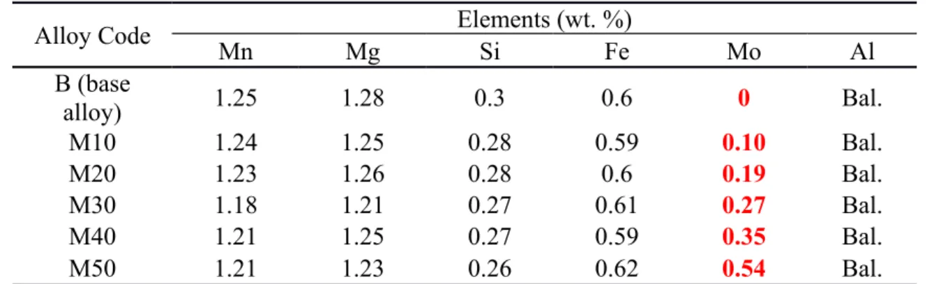
Al-Mn-Mg 3004 alloys with different Mo additions were prepared using commercially pure Al (99.7%), pure Mg (99.9%), Al-25%Mn, Al-25%Fe, Al-50%Si and Al-10%Mo master alloys. In each test, approximately 3 kg of material was prepared in a clay-graphite crucible using an electric resistance furnace. The temperature of the melt was maintained at ~750°C for 30 min. The melt was degassed for 15 min and then poured into a permanent mold preheated at 250°C. The dimension of the cast ingots was 30mm×40mm×80mm. The chemical compositions of the experimental 3004 alloys analyzed with an optical emission spectrometer were shown in Table 1 (all of the alloy compositions are in wt. % unless indicated otherwise).
Table 1 Chemical compositions of experimental alloys used in present work
Alloy Code Elements (wt. %)
Mn Mg Si Fe Mo Al
B (base
alloy) 1.25 1.28 0.3 0.6 0 Bal.
M10 1.24 1.25 0.28 0.59 0.10 Bal.
M20 1.23 1.26 0.28 0.6 0.19 Bal.
M30 1.18 1.21 0.27 0.61 0.27 Bal.
M40 1.21 1.25 0.27 0.59 0.35 Bal.
M50 1.21 1.23 0.26 0.62 0.54 Bal.
To explore the elevated temperature properties and their thermal stability, two types of heat treatments were performed in the present work, as listed in Table 2. The first was the precipitation treatment at 375~550°C for up to 48 hours to study the evolution of dispersoids and elevated-temperature properties at different heat treatment conditions.
After the precipitation treatments, the ingots were directly quenched in water at room temperature (RT). The second type of heat treatment was the long-term thermal holding at 350°C and 400°C to examine the thermal stability of the mechanical properties for selected sample conditions. The thermal stability at 300°C was demonstrated in our previous work [3], and therefore, the relatively higher temperatures (350°C and 400°C)
were selected in the present work. Prior to the long-term thermal holding, samples were always heat-treated with a peak precipitation heat treatment (375°C/48h) [3].
Table 2 Parameters of the heat treatments used in the present work
Heat treatments Temperature, °C Time, h
Precipitation treatment 375, 425, 475, 500, 525,
550 up to 72
Thermal Holding 350, 400 up to 1000
After heat treatment, the samples were polished for metallographic observations and machined for property tests. To reveal the dispersoids clearly, the polished samples were etched in 0.5% HF for 30 seconds. An optical microscope (OM) and a scanning electron microscope (SEM) were used to observe the as-cast and heat-treated microstructures. A transmission electron microscope (TEM) was used to observe the distribution of dispersoids in detail. The thickness of the TEM sample was measured with electron energy loss spectroscopy (EELS). The size and number density of dispersoids were measured using Clemex PE 4.0 image analysis software with the TEM images. In this study, the vol. % of DFZ was converted from the area fraction of DFZ measured in image analysis from optical images according to Delesse’s principle [27, 28], while the vol. % of dispersoids was calculated according to the method introduced in the literature [1] and is shown in Eq. (1):
Vv=Ad K´ D´
K´ D+t´
(
1−ADFZ)
(1)
where D´ is the average equivalent diameter of dispersoids, which was calculated according to the literature [3]; t is the TEM foil thickness; Ad is the area percentage of dispersoids from TEM observation; ADFZ is the area percentage of DFZ from OM measurements; and K´ is the average shape factor of dispersoids.
Additionally, Vickers microhardness, YS and creep properties were measured after various heat treatments. The microhardness was measured at RT. The mechanical property (YS) at both room and elevated temperatures (300°C) was obtained from compression tests at a strain rate of 10-3/s, which were performed on a Gleeble 3800 thermomechanical simulator unit using cylindrical specimens (15 mm in length and 10 mm in diameter). For the compression test at elevated temperatures, the specimen was heated to the required temperatures with a heating rate of 2°C/s and held for 3 minutes to stabilize. The compressive creep tests were performed at 300°C for 100 hours with a constant load of 45 MPa. The creep specimens were the same size as the Gleeble samples. Details of test methods can be found in our previous paper [3].
3. Results and discussion
3.1 Evolution of the microstructure and mechanical properties with various Mo contents
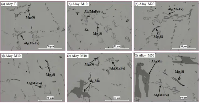
Fig. 1 shows the as-cast microstructures of experimental alloys. It can be seen that the microstructures are similar when Mo addition is lower than 0.35% (M40). In such alloys, microstructures were composed of dominant Al6(MnFe) and minor Mg2Si intermetallic phases were distributed in the interdendrite regions [3]. No Mo had been detected in these intermetallic phases, indicating that almost all of the added Mo was dissolved in the Al matrix. However, the primary Mo-containing intermetallic particles began to form in M40 with 0.35% Mo, and the size and the vol. % increased with increasing Mo content (M50 in Fig. 1f). According to the SEM-EDS results and Al-Mo binary phase diagram [22], the primary Mo-containing intermetallic particles are identified as Al12Mo, as shown in Fig. 1e and 1f.
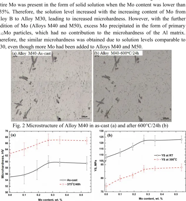
Fig. 1 As-cast microstructures of experimental alloys with various Mo contents In an attempt to dissolve the primary Al12Mo particles, traditional homogenization treatment for 3xxx alloys (600°C/24h) was performed on Alloy M40. To observe the in-situ evolution of Al12Mo during homogenization, the samples were first grinded and polished in the as-cast condition and then held at 600°C for 24 hours. After homogenization, the sample was only slightly polished to remove the oxide film. A mark was made on the sample at a well-located observation area to ensure the same position after casting and homogenization. The results from in-situ observations are shown in Fig. 2. Compared with the as-cast condition in Fig. 2a, no remarkable change occurred on primary Al12Mo particles, even after 600℃/24h. This can be attributed to the higher formation temperature of Al12Mo intermetallics based on the Al-Mo phase diagram, which is higher than 700°C [22]. Therefore, the Mo contents should be less than 0.35% to avoid the formation of primary Al12Mo particles from the microstructure view, which is stable and cannot be dissolved even at high temperature (~600 °C).
The microhardness of as-cast experimental alloys was measured, and the results are shown in Fig. 3a. It was found that the microhardness initially increased as the Mo
content was increased to 0.3% Mo and then remained stable. This can be explained with the solution level of Mo under various Mo additions. As shown in Fig. 1, almost the entire Mo was present in the form of solid solution when the Mo content was lower than 0.35%. Therefore, the solution level increased with the increasing content of Mo from Alloy B to Alloy M30, leading to increased microhardness. However, with the further addition of Mo (Alloys M40 and M50), excess Mo precipitated in the form of primary Al12Mo particles, which had no contribution to the microhardness of the Al matrix.
Therefore, the similar microhardness was obtained due to solution levels comparable to M30, even though more Mo had been added to Alloys M40 and M50.
Fig. 2 Microstructure of Alloy M40 in as-cast (a) and after 600°C/24h (b)
Fig. 3 Evolution of microhardness and YS with the addition of Mo in as-cast and heat- treated samples under 375°C/48h conditions
In addition, one precipitation heat treatment (375°C/48h) was performed to verify the evolution of mechanical properties with different Mo levels during the heat treatment.
As shown in Fig. 3a, the microhardness after 375°C/48h was much higher than that of the as-cast condition at any given Mo level, indicating the effective improvement of mechanical properties due to Mo addition. Additionally, the microhardness after 375°C/48h increased with the increasing Mo level and reaches the peak value at 0.3%Mo, after which it plateaus. Fig. 3b shows the YS at both RT and 300℃ after heat treatment
(375°C/48h). Similar to the evolution of microhardness, YS at both RT and 300℃
increases first to 0.3% Mo and then remains constant in Alloys M40 and M50.
As shown in Fig. 3, the mechanical properties in both as-cast and heat-treated samples reached peak values at 0.3% Mo. When Mo fractions higher than 0.35% were added, the mechanical properties had no greater improvement because of the formation of primary Al12Mo particles, which were difficult to dissolve even after higher temperature homogenization (600°C/24h). Therefore, the Mo content can be optimized at 0.3% from both microstructure and property views. In the following sections, Alloy M30 with 0.3%
Mo and Alloy B as the base alloy were selected to study the influence of Mo on elevated- temperature properties in more detail.
3.2 Elevated-temperature strengths after various heat treatments
To study the evolution of elevated-temperature strengths with Mo addition, the changes of microhardness at RT of Alloys B and M30 after various heat treatments within the temperature range of 375 to 500°C were first checked, and the results are shown in Fig. 4. It can be observed that the microhardness of Alloy M30 was always higher than that of Alloy B after the same heat treatments at all studied temperatures, confirming the positive influence of Mo on the properties. For instance, the microhardness of Alloy M30 was 67 HV, which was much higher than 61 HV in Alloy B after 425°C/4h (Fig. 4b).
Fig. 4 Evolution of microhardness of Alloys B and M30 during various heat treatments Fig. 4a shows the microhardness with increasing holding time at 375°C, which is reported to be the optimized temperature for the precipitation of dispersoids [3].
Generally, the microhardness increases with time for both alloys due to the continuous precipitation of dispersoids [3]. For base Alloy B, microhardness reaches its peak after 24-48 hours and then remains stable, but it seems still to have a slight increase after 48 hours for Alloy M30, which can be attributed to the continuous precipitation of dispersoids due to the low diffusion rate of Mo. However, the rate of increase after 24-48 hours is quite lower. Therefore, the peak heat treatment at 375°C/24-48 hours can be suggested for both alloys.
With the increasing temperature of heat treatments, microhardness decreases after the peak for both alloys, which is related to the precipitation and the following coarsening of dispersoids with holding time [3]. However, the rate of decrease after the peak value with increasing holding time is much higher in Alloy B than M30, especially at higher temperatures. As shown in Fig. 4b, no obvious decrease on microhardness can be observed in both alloys after the peak value at 425°C/4h. However, it began to rapidly decrease after reaching the peak at 500℃/2h in Alloy B, while it only slightly decreased in Alloy M30 (Fig. 4c). At higher temperatures (550 °C), the gap became larger between the two alloys with increasing treatment time (Fig. 4d). For instance, after 550°C/24h (Fig. 4d), the microhardness rapidly decreased from its peak of 57 HV to 51 HV hours in Alloy B, while it has fallen only 3 HV from its peak of 64 HV to 61 HV in Alloy M30.
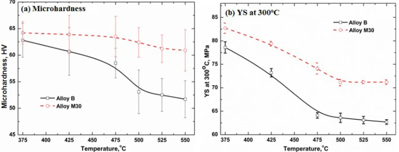
Fig. 5 displays the evolution of microhardness and YS at 300°C after 24 hours at various temperatures. It can be seen that both the microhardness and YS decreased with temperature, but the rate of decrease is higher in Alloy B than in M30 with increasing temperature. When the temperature increases from 375°C to 550°C, the microhardness was decreased from 62 HV to 51 HV in Alloy B, but it dropped only 3 HV from 64 HV to 61 HV in Alloy M30 (Fig. 5a). The YS at 300°C was reduced from 78 MPa to 62 MPa in Alloy B while a smaller amount is reduced (82 MPa to 71 MPa) in Alloy M30 (Fig.
5b), indicating the significant impact of Mo addition on the elevated-temperature strengths. It is evident that Mo can improve the elevated-temperature strengths in all of the treatment temperatures studied. The strengthening effect is considerably higher when treated at relatively low temperatures (375-425°C) than at higher temperatures (500- 550°C).
The remarkable enhanced microhardness and elevated-temperature strengths in Alloy M30, even at higher temperatures, can likely be attributed to the improved precipitation behavior of dispersoids and DFZs due to the Mo additions. The formation and distribution of dispersoids after 375°C/48h in Alloy B and M30 were examined with OM and TEM, and the results are shown in Fig. 6. Compared with the base Alloy B (Fig. 6a), the density of dispersoids was higher in Alloy M30 (Fig. 6d), which was confirmed from the TEM observation in Fig. 6e. The size of precipitated dispersoids was
similar in both alloys, but the vol. % of dispersoids was higher in Alloy M30. It is also evident that the area of DFZ was smaller in Alloy M30 than in Alloy B (Figs. 6a and 6d), which was also confirmed by the quantitative image analysis shown in Fig. 9a. The vol.
% of DFZ was measured to be 20% in Alloy M30 and 28% in Alloy B. In addition, the dispersoids changed from α-Al(MnFe)Si in Alloy B [2,3] to α-Al(MnFeMo)Si in Alloy M30, as shown in Fig. 6f.
Fig. 5 Evolution of alloy properties after 24h treated at various temperatures
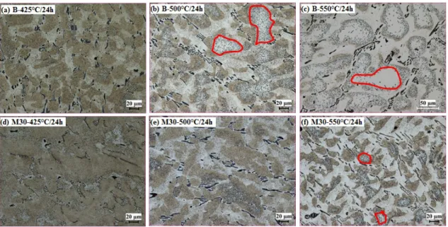
Fig. 6 Distribution and composition of dispersoids in Alloys B and M30 after 375°C/48h Fig. 7 shows the distribution of dispersoids and DFZ in Alloys B and M30 after heat-treatment at three temperatures for 24 hours. Generally, the vol. % of DFZ increases with increasing temperature. In Alloy B, the DFZ began to increase at 425°C in the interdendrite regions (Fig. 7a), while the DFZs in the centers of dendrites (indicated by
red circles) formed at 500℃ (Fig. 7b) with volumes rapidly increasing at 550°C (Fig. 7c).
However, no obvious change in DFZs at 425°C in Alloy M30 can be observed in either interdendrites or the centers of dendrites. At 500°C, interdendritic DFZs seem to increase with litter DFZs in the centers of dendrites (Fig. 7e), while only a few zones with DFZs in the centers of dendrites are present at 550°C (Fig. 7f). The evolution of DFZs with the heat treatment temperature is shown in Fig. 9a. It can be found that the vol. % of DFZs in Alloy M30 was always lower than that in Alloy B under the same temperature condition, though the DFZ amount increased with increasing temperature for both alloys. The vol.
% of DFZ was slowly increased from 21% after 425°C/24h to 30% after 500°C/24h and 39% after 550°C/24h in Alloy M30, while it rapidly increased from 28% after 425°C/24h to 45% after 500°C/24h and 58 % after 550°C /24h in Alloy B.
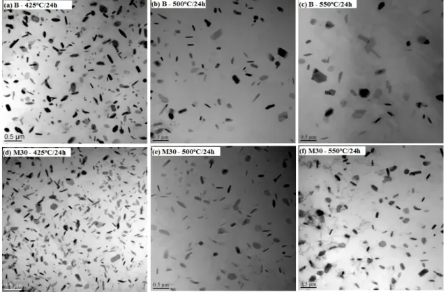
Fig. 7 Evolution of DFZs after various heat treatments in Alloys B and M30 The distribution of dispersoids after various heat treatments is shown in the TEM images of Fig. 8. Similar to the tendency of DFZs, dispersoids become bigger with a lower vol. % for both alloys with increasing treatment temperature. However, the dispersoid behavior varies with Alloys B and M30, in which the coarsening of dispersoids in Alloy B is much faster than in Alloy 30. As shown in Fig. 8a-c, the size of dispersoids sharply increased while the volume fraction rapidly decreased in Alloy B compared with Alloy M30 (Fig. 8d-8f). It can be seen in Fig. 9b that the size of dispersoids increased more quickly while their vol. % decreased more rapidly in Alloy B compared to Alloy M30, especially at higher temperatures. For instance, the size of dispersoids in Alloy B was already coarsened to 135 nm in Alloy B, while it was only 105 nm in Alloy M30 after 550°C/24h. Meanwhile, the vol. % of dispersoids in Alloy B was 0.62 %, while it was still as high as 1.86 % in Alloy M30.
The differences of DFZ in Alloys B and M30 can be derived from the negative segregation and low diffusivity of Mo. Mo is reported to segregate in the centers of
dendrites (negative segregation with a distribution coefficient k of 2.5 [22, 24]), while Mn segregates towards the dendrite boundaries (positive segregation with a distribution coefficient k of 0.7 [16]). Therefore, Mo is available to form dispersoids in the centers of dendrites during the heat treatments in Alloy M30, leading to its lower volume of DFZs and higher volume of dispersoids. Meanwhile, the low diffusion rate of Mo [25, 26]
results in a lower coarsening of dispersoids as well as less interdendritic DFZs during heat treatments in Alloy M30. Therefore, Alloy M30 exhibits higher microhardness and elevated-temperature strengths in all heat treatment conditions, especially at higher temperatures. It is expected that to retain their excellent elevated-temperature properties, it is easier for Mo-containing Al-Mn-Mg alloys to adapt to conventional thermomechanical fabrication processes, such as extrusion and rolling, in which a pre-heating at 475-550°C may be needed, leading to sharply decreased strengths in Alloy B, as shown in Figs. 4 and 5.
Fig. 8 Behaviors of dispersoids after various heat treatments in Alloys B and M30
Fig. 9 Evolution of DFZ (a) and dispersoids (b) after various heat treatments 3.3 Thermal stability of elevated-temperature mechanical properties with Mo addition
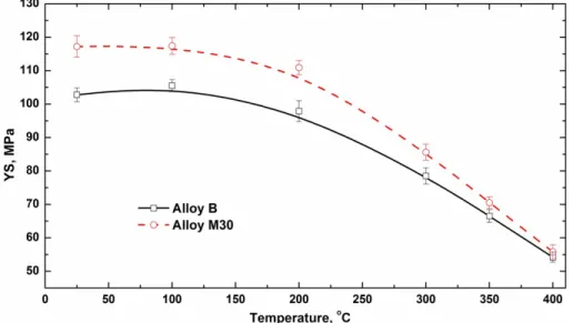
As shown in Figs. 4 and 5, the alloys with Mo additions can have higher elevated- temperature mechanical properties and a lower rate of decrease with temperature, even at higher temperatures, providing a wider potential service temperature range for the Al-Mn-Mg 3004 alloy. Fig. 10 shows the evolution of YS as a function of the test temperature after peak treatment at 375°C/48h in Alloys B and M30. It can be found that the YS of Alloy M30 were always higher than those of the base alloy (Alloy B) up to 350°C, confirming the overall improvement of strength by Mo addition at high service temperatures. For instance, the YS values at 300°C and 350°C in Alloy M30 were 86 and 71 MPa, respectively, which were 10% and 6% increases compared with Alloy B.
When the test temperature was increased to 400°C, the YS values of both alloys became close.
Fig. 10 Evolution of YS as a function of the test temperature for both Alloys B and M30 On the other hand, the thermal stability of the mechanical properties is an important consideration for the alloys used at elevated temperatures [12, 29, 30]. In our previous work [3], it was demonstrated that the Al-Mn-Mg 3004 alloy was thermally stable at 300°C. Therefore, in the present work, thermal stabilities at higher temperature (350°C and 400°C) were tested for Alloys B and M30. The YS at two different holding temperatures after the peak precipitation treatment (375°C /48h) is displayed in Fig. 11.
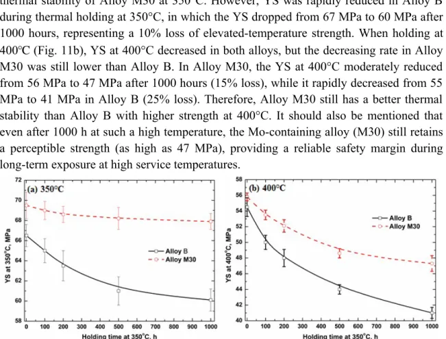
Fig. 11a shows the evolution of YS at 350℃ during thermal holding in Alloys B and M30. It can be seen that YS was considerably stable in Alloy M30, even after 1000 hours, which only slightly decreased from 69.5 MPa to 68 MPa, indicating the excellent
thermal stability of Alloy M30 at 350°C. However, YS was rapidly reduced in Alloy B during thermal holding at 350°C, in which the YS dropped from 67 MPa to 60 MPa after 1000 hours, representing a 10% loss of elevated-temperature strength. When holding at 400℃ (Fig. 11b), YS at 400°C decreased in both alloys, but the decreasing rate in Alloy M30 was still lower than Alloy B. In Alloy M30, the YS at 400°C moderately reduced from 56 MPa to 47 MPa after 1000 hours (15% loss), while it rapidly decreased from 55 MPa to 41 MPa in Alloy B (25% loss). Therefore, Alloy M30 still has a better thermal stability than Alloy B with higher strength at 400°C. It should also be mentioned that even after 1000 h at such a high temperature, the Mo-containing alloy (M30) still retains a perceptible strength (as high as 47 MPa), providing a reliable safety margin during long-term exposure at high service temperatures.
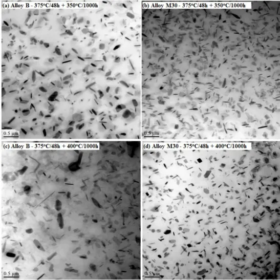
Fig. 11 Evolution of YS during a long-term thermal holding in Alloys B and M30 During long-term thermal holding, the coarsening of dispersoids is controlled by the diffusion of the main alloying elements in dispersoids, such as Mn in Alloy B and Mo in Alloy M30, which is a return to the control of the mechanical properties. Fig. 12 shows TEM images of the dispersoid evolution after 1000 hours at 350°C and 400°C in Alloys B and M30. Compared with the dispersoids after 375°C/48h in Fig. 6b, it can be found that the dispersoids became coarsened with a decreasing vol. % in Alloy B (Fig. 12a) after holding for 1000 hours at 350°C, resulting in decreased strength. However, as shown in Fig. 12b, only minor changes occurred in either the size or the vol. % of dispersoids in Alloy M30, which resulted from a slower coarsening rate, leading to its excellent thermal stability of strength at 350 °C.
During thermal holding at 400°C, which is much higher than the formation temperature of dispersoids (~ 342°C [3]), the coarsening rate of dispersoids was much higher in Alloy B than at 350°C . As shown in Fig. 12c, the size of dispersoids was grown to ~ 200 nm, resulting in a sharp drop of YS during the long-term thermal holding at 400°C in Alloy B. On the other hand, the dispersoids also coarsened at 400°C in Alloy M30, leading to the decease of YS at 400°C. However, the lower diffusion rate of Mo leads to a slower coarsening rate of dispersoids. It is reported that the diffusion rate of Mo is 5.5 × 10⁻²³ m2 s-1 at 400°C, which is four orders of magnitude lower than that of Mn
(6.3 × 10⁻¹⁹ m2) [24]. Therefore, it is reasonable to expect a lower coarsening rate of Mo- containing dispersoids in Alloy M30 compared with that of Mo-free dispersoids in Alloy B (Fig. 12d), resulting in higher YS values and a slower rate of decrease of YS in Alloy M30 than in Alloy B during holding at 400°C.
Fig. 12 Behaviors of dispersoids during long thermal holding in Alloys B and M30 In brief, Alloy M30 is thermally stable up to 350°C and exhibits a slight decrease of the stability when thermal holding at 400°C. Compared to the base alloy, Alloy M30 can provide a much wider service temperature range to meet the increasing industrial demand for elevated-temperature applications of aluminum alloys.
3.4 Elevated-temperature creep properties with Mo addition
Creep resistance is considered to be one of the most important properties for the design and selection of high temperature alloys [24, 31, 32]. Compressive creep tests at 300°C were performed for Alloys B and M30 after two heat treatment conditions: one at
the peak treatment (375°C/48h) and the other at a higher temperature (550°C/24h). The results are shown in Fig. 13.
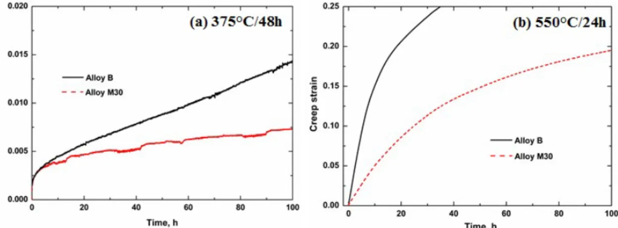
The creep curves in Fig. 13 reveal that the creep resistance treated at high temperature (550°C/24h) was lower than that treated at the peak treatment (375°C/48h) for both alloys, but the creep resistance in Alloy M30 was remarkably higher than in Alloy B at both heat treatment conditions. After treatment at 375°C/48h, the total creep stain in Alloy B was higher than that in Alloy M30 (Fig. 13a). Moreover, the minimum creep rate was calculated to be 3.1× 10⁻⁸ s-1 for Alloy B, while it is only 9.5× 10⁻⁹ s-1 for Alloy M30, which was 3 times lower than that for Alloy B, as shown in Table 3. The difference was also obvious after treatment at 550°C/24h, in which the total creep strain reached the strain limitation (0.25) of the creep machine after only 37 hours in Alloy B, while it was still less than 0.2 even after 100 hours in Alloy M30 (Fig. 13b). This can be explained by the behavior of dispersoids in two different alloys after heat treatment.
According to the creep condition applied in the present work (45 MPa at 300°C), the creep mechanism is primarily controlled by dislocation movements [33], which greatly depend on the size and amount of dispersoids. After the peak treatment (375℃/48h), the precipitated dispersoids were fine in both alloys, but the relatively higher vol. % of dispersoids in Alloy M30 results in a lower creep stain and minimum creep rate compared to Alloy B. With increasing treatment temperature (550°C/24h), the precipitated dispersoids became coarse with a decreasing vol. % in both alloys, leading to a higher creep strain and minimum creep rate than in samples treated at 375°C/48h (Figs 6 and 7). However, the dispersoids in Alloy M30 after treatment at 550°C/24h were more coarsening resistant, and their sizes were finer with higher vol. % than in Alloy B (Figs. 8 and 9), resulting in a higher creep resistance in the Mo-containing Alloy M30.
Fig. 13 Compression creep curves after various treatments in Alloys B and M30 Creep tests are also performed for Alloys B and M30 after long-term thermal holding at 350°C and 400°C for 1000 hours, and the results are displayed in Fig. 14. The creep properties (total creep strain and minimum creep rate) are calculated in Table 3 for three sample treatment conditions (the peak treatment, 375°C/48h + 350°C/1000h, and 375°C/48h + 400°C/1000h). Compared with the samples directly after the peak treatment
(Fig. 13a), the creep resistance of the samples after long-term thermal holding were moderately decreased. For example in Alloy B, as shown in Table 3, the total creep stain increased from 0.0143 (after 375°C/48h) to 0.108 (after 375°C/48h+350°C/1000h), while the minimum creep rate also increased from 3.1×10⁻⁸ (after 375°C/48h) to 2.9×10⁻⁷ (after 375°C/48h+350°C/1000h). With an increasing holding temperature from 350 to 400°C, the creep resistance further slightly decreased. The same tendency is also found in Alloy M30 (Table 3). This can be attributed to the coarsening process of dispersoids during the long-term thermal holding. As shown in Fig. 12a and b, the dispersoids became coarsened in both Alloy B and M30 after holding for 1000 hours at 350°C compared with the dispersoids shown in Fig. 6 after the peak heat treatment (375°C/48h).
Fig. 14 Creep curves after long-time thermal holding process in Alloys B and M30 Table 3 Creep properties after peak treatment and long-term thermal holding
in Alloys B and M30
Alloy code
375°C/48h 375°C/48h +
350°C/1000h 375°C/48h +
400°C/1000h Total
creep strain
Minimum creep rate,
s-1
Total creep strain
Minimum creep rate,
s-1
Total creep strain
Minimum creep rate,
s-1 Alloy B 0.0143 3.1× 10⁻⁸ 0.108 2.9× 10⁻⁷ 0.165 4.2× 10⁻⁷ Alloy M30 0.0074 9.6× 10⁻⁹ 0.012 1.8 × 10⁻⁸ 0.015 3.2× 10⁻⁸
However, at the same thermal holding condition, the creep resistance of Mo-containing alloy (M30) was much better than that of the base alloy. In other words, the total creep strain and minimum creep rate were much lower in Alloy M30 than Alloy B at both the 350°C and 400°C holding conditions (Fig. 14). As shown in Table 3, the total creep strain after 375°C/48h+400°C/1000h was only 0.015 with the minimum creep rate of 3.2×10⁻⁸ s-1 in Alloy M30, while it was 0.165 with the minimum creep rate of 4.2×10⁻⁷ s-1 in Alloy B, which was one order of magnitude higher than in Alloy M30. It is also interesting to note that the creep properties in Alloy M30 after 375°C/48h+400°C/1000h were even similar to those of Alloy B after 375°C/48h. The
results demonstrate a significant improvement of the creep resistance at elevated temperatures due to the addition of Mo. This is mainly attributed by the slower coarsening rate of Mo-containing dispersoids in Alloy M30 during long-term thermal holding, which is shown in Fig. 12, with finer dispersoids and higher vol. % in Alloy M30 than in Alloy B after both 350°C/1000h and 400°C/1000h holdings.
4. Conclusions
(1) When Mo is added up to 0.3%, little change in the as-cast microstructure is observed. The primary Al12Mo intermetallic particles start forming when Mo addition is higher than 0.35%, and they are difficult to dissolve even after high temperature homogenization at 600°C/24h.
(2) In both as-cast and heat-treated conditions, both microhardness and YS increase with increasing Mo content and reach the peak value at 0.3% Mo, followed by a plateau with a further increase of Mo.
(3) With the addition of 0.3% Mo, the size of dispersoids becomes finer with a higher volume fraction, while the volume percentage of dispersoid-free zones is greatly reduced compared to the base alloy. A remarkable improvement of elevated-temperature YS and creep resistance with Mo addition is obtained.
(4) The elevated-temperature properties decrease with increasing temperature and holding time of heat treatment. However, the rate of decrease is much slower in alloys with 0.3% Mo than in the base alloy, making Al-Mn-Mg alloys easier to adapt in the conventional fabrication process.
(5) Compared with the rapid drop of elevated-temperature strength and creep resistance in the base alloy free of Mo, the Al-Mn-Mg alloy with 0.3% Mo is thermally stable up to 350°C, and it exhibits a slight decrease of stability at 400°C. These characteristics provide a much wider service temperature range of Al-Mn-Mg alloys for elevated-temperature applications.
Acknowledgement
The authors would like to acknowledge the financial support from the Natural Sciences and Engineering Research Council of Canada (NSERC) and Rio Tinto Aluminum, through the NSERC Industry Research Chair in Metallurgy of Aluminum Transformation at the University of Quebec at Chicoutimi.
Reference
[1] Y.J. Li, L. Arnberg, Acta Mater., 51 (2003) 3415-3428.
[2] Y.J. Li, A.M.F. Muggerud, A. Olsen, T. Furu, Acta Mater., 60 (2012) 1004-1014.
[3] K. Liu, X.G. Chen, Mater. Des., 84 (2015) 340-350.
[4] K. Liu, X.G. Chen, Metall. Mater. Trans. B, (2015) 1-10.
[5] J.G. Kaufman, Properties of aluminum alloys : tensile, creep, and fatigue data at high and low temperatures, ASM International ; Aluminum Association, Materials Park, Ohio;
Washington, D.C., 1999.
[6] H.-W. Huang, B.-L. Ou, Mater. Des., 30 (2009) 2685-2692.
[7] A.M.F. Muggerud, E.A. Mørtsell, Y. Li, R. Holmestad, Mater. Sci. Eng., A, 567 (2013) 21-28.
[8] K. Liu, X. -G.Chen, to be submitted, (2016).
[9] K. Liu, X.-G. Chen, to be submitted, (2016).
[10] C. Booth-Morrison, D.C. Dunand, D.N. Seidman, Acta Mater., 59 (2011) 7029- 7042.
[11] K.E. Knipling, R.A. Karnesky, C.P. Lee, D.C. Dunand, D.N. Seidman, Acta Mater., 58 (2010) 5184-5195.
[12] J. Lai, Z. Zhang, X.G. Chen, Mater. Sci. Eng., A, 532 (2012) 462-470.
[13] M.E. Van Dalen, D.C. Dunand, D.N. Seidman, J. Mater. Sci., 41 (2006) 7814-7823.
[14] M.E. Van Dalen, T. Gyger, D.C. Dunand, D.N. Seidman, Acta Mater., 59 (2011) 7615-7626.
[15] Y. Li, L. Arnberg, Precipitation of Dispersoids in DC-Cast AA31O3 Alloy during Heat Treatment, in: F. Grandfield, D.G. Eskin (Eds.) Essential Readings in Light Metals, John Wiley & Sons, Inc., Hoboken, NJ, USA, 2013, pp. 1021-1027.
[16] G.K. Sigworth, International Journal of Metalcasting, 8 (2015) 7-20.
[17] B. Forbord, H. Hallem, J. Røyset, K. Marthinsen, Mater. Sci. Eng., A, 475 (2008) 241-248.
[18] K.E. Knipling, D.C. Dunand, D.N. Seidman, Acta Mater., 56 (2008) 114-127.
[19] L. Lodgaard, N. Ryum, Mater. Sci. Eng., A, 283 (2000) 144-152.
[20] P.Y. Li, H.J. Yu, S.C. Chai, Y.R. Li, Scripta Materialia, 49 (2003) 819-824.
[21] Y. Barbaux, G. Pons, Journal de Physique IV Colloque, 03 (1993) 191-196.
[22] A.R. Farkoosh, X. Grant Chen, M. Pekguleryuz, Mater. Sci. Eng., A, 620 (2015) 181-189.
[23] A.R. Farkoosh, X.G. Chen, M. Pekguleryuz, Mater. Sci. Eng., A, 627 (2015) 127- 138.
[24] K.E. Knipling, D.C. Dunand, D.N. Seidman, Z. METALLKD, 97 (2006) 246-265.
[25] N.V. Chi, D.Bergner, in: F.J. Kedves, D.L. Beke (Eds.) DIMETA-82: Diffusion in Metals and. Alloys, Trans Tech Publications, Switzerland, 1983, pp. 334-337.
[26] Y. Du, Y.A. Chang, B. Huang, W. Gong, Z. Jin, H. Xu, Z. Yuan, Y. Liu, Y. He, F.Y.
Xie, Mater. Sci. Eng., A, 363 (2003) 140-151.
[27] P.X. Liu, Y. Liu, R. Xu, Trans. Nonferrous Met. Soc. China, 24 (2014) 2443-2451.
[28] E.R. Weibel, H. Elias, S. International Society for, Quantitative methods in
morphology. Quantitative Methoden in der Morphologie; proceedings, Springer-Verlag, Berlin; New York, 1967.
[29] R. Mahmudi, F. Kabirian, Z. Nematollahi, Mater. Des., 32 (2011) 2583-2589.
[30] T. Öz, E. Karaköse, M. Keskin, Mater. Des., 50 (2013) 399-412.
[31] Y. Li, T.G. Langdon, Acta Mater., 46 (1998) 1143-1155.
[32] S.M. Miresmaeili, B. Nami, Mater. Des., 56 (2014) 286-290.
[33] G.E. Dieter, Mechanical metallurgy, McGraw-Hill, New York, 1976.