Adaptive Sampling in Autonomous Marine Sensor
Networks
by
Donald Patrick Eickstedt
B.S., Electrical Engineering, Michigan Technological University (1987)
M.S., Computer Science, The Johns Hopkins University (1993)
Submitted in partial fulfillment of the requirements for the degree of
Doctor of Philosophy
at the
MASSACHUSETTS INSTITUTE OF TECHNOLOGY
and the
WOODS HOLE OCEANOGRAPHIC INSTITUTION
June 2006
@ Massachusetts Institute of Technology 2006. All rights reserved.
Author ... ...
...
Joint Program in Oceanography/Applied Ocean Science and Engineering Massachusetts Institute of Technology and s o graphic Institution
June, 2006
Certified by ...
Henrik Schmidt Professor, Depa ent of Mechanical Engineering
Thesis Supervisor
Accepted by...
Henrik Schmidt
Chair, JoinCommittee if ied Ocean Science and Engineering Massachusetts Institute of Technology and Woods Hole Oceanographic Institution
Accepted by... AF...
Lallit Anand Chair, Committee on Graduate Students, Department of Mechanical Engineering
MASSA CHUSETrsISTUE OF TECHNOLOGY
Adaptive Sampling in Autonomous Marine Sensor Networks
by
Donald Patrick Eickstedt
Submitted to the Joint Program in Oceanography/Applied Ocean Science and Engineering
and the Massachusetts Institute of Technology and Woods Hole Oceanographic Institution
on June, 2006, in partial fulfillment of the requirements for the degree of
Doctor of Philosophy
Abstract
In this thesis, an innovative architecture for real-time adaptive and cooperative control of autonomous sensor platforms in a marine sensor network is described in the context of the autonomous oceanographic network scenario. This architecture has three major compo-nents, an intelligent, logical sensor that provides high-level environmental state information to a behavior-based autonomous vehicle control system, a new approach to behavior-based control of autonomous vehicles using multiple objective functions that allows reactive con-trol in complex environments with multiple constraints, and an approach to cooperative robotics that is a hybrid between the swarm cooperation and intentional cooperation ap-proaches. The mobility of the sensor platforms is a key advantage of this strategy, allowing dynamic optimization of the sensor locations with respect to the classification or localiza-tion of a process of interest including processes which can be time varying, not spatially isotropic and for which action is required in real-time.
Experimental results are presented for a 2-D target tracking application in which fully autonomous surface craft using simulated bearing sensors acquire and track a moving target in open water. In the first example, a single sensor vehicle adaptively tracks a target while simultaneously relaying the estimated track to a second vehicle acting as a classification platform. In the second example, two spatially distributed sensor vehicles adaptively track a moving target by fusing their sensor information to form a single target track estimate. In both cases the goal is to adapt the platform motion to minimize the uncertainty of the target track parameter estimates. The link between the sensor platform motion and the target track estimate uncertainty is fully derived and this information is used to develop the behaviors for the sensor platform control system. The experimental results clearly illustrate the significant processing gain that spatially distributed sensors can achieve over a single sensor when observing a dynamic phenomenon as well as the viability of behavior-based control for dealing with uncertainty in complex situations in marine sensor networks.
Thesis Supervisor: Henrik Schmidt
Acknowledgments
This work is the result of not only my own effort but also that of the numerous individuals who have supported me along the way without whom this work would never have begun or would never have been finished.
First and foremost I thank my wife Margaret whose love and support have enabled me to accomplish one of my life's goals. You've been the force that's kept our family together through the past seven years. I can never repay the sacrifices you've made and I will never forget them either.
I would like to thank my adviser Henrik Schmidt for having the faith to choose me for his
group and for letting me have as much responsibility as I could handle. Your patience with me as I struggled with this program at times and your support at several critical times is very appreciated and won't be forgotten. The same goes for Professor John Leonard whose key support at at least one critical point helped keep me in this program. Your insight and advice through the years is also greatly appreciated.
I would like to thank my other committee members Mike Benjamin and Hanumant Singh for your efforts on my committee. Even though you're both very busy I appreciate that you took the time to help guide me through this last part of my program. Your advice was invaluable. I would also like to thank Mike for his collaboration on a number of research experiments which appear in this report. I look forward to more collaboration in the future.
I would also like to thank my sponsor, the Office of Naval Research, who supported my work with a 3-year National Defense Science and Engineering Grant Fellowship and funded my research assistantships through the Generic Ocean Array Technology Sonar (GOATS) project, contract
N00014-97-1-0202 and contract N00014-05-G-0106 Delivery Order 008, PLUSNET: Persistent
Contents
1 Introduction 17
1.1 Requirements for a Marine Sampling Network . . . 20
1.1.1 Mobility . . . 20
1.1.2 Adaptivity . . . . 21
1.1.3 Communications . . . . 23
1.1.4 Cooperation . . . . 23
1.1.5 Sensor Fusion . . . . 24
1.2 Other Adaptive Sampling Work . . . . 25
1.3 Preview of Results . . . . 25
1.4 Thesis Organization . . . . 26
2 Autonomous Oceanographic Sampling Networks 27 2.1 System Concept . . . . 28
2.1.1 Number of Sensor Platforms Required. . . . . 29
2.1.2 Sensor Platform Type . . . 30
2.1.3 Acoustic Communications and Navigation. . . . 32
2.1.4 Vehicle cost. . . . 33
2.2 Enabling Technologies. . . . 34
2.3 Historical Developments . . . . 34
2.3.1 The AOSN Project . . . . 34
2.3.2 The AOSN-II Project . . . . 35
2.3.3 The NEPTUNE Project . . . 36
3 Adaptive Sensor Platform Control 39
3.1 The World Model-Based Approach ... ... 40
3.2 Behavior-Based Approaches ... 41
3.2.1 Subsumption Architecture ... 41
3.2.2 State-Configured Layered Control ... 42
3.2.3 M otor Schemas . . . 43
3.2.4 The Multiple Objective Function Approach . . . 44
3.3 Cooperative Control . . . 45
3.3.1 Swarm Cooperation . . . 46
3.3.2 Intentional Cooperation . . . 47
3.3.3 Formation/Flocking Behaviors . . . 47
4 The MOOS-IvP Autonomy Architecture 51 4.1 A Distributed Control Architecture for Marine Sensor Platforms . . . 51
4.1.1 Behavior-Based Control with Interval Programming . . . 51
4.1.2 The MOOS-IvP Autonomy Architecture . . . 52
4.2 Sensor Platform Behaviors . . . 53
4.2.1 The OpRegion Behavior . . . . 54
4.2.2 The Waypoint Behavior . . . . 54
4.2.3 The Orbit Behavior . . . . 54
4.2.4 The ArrayTurn Behavior . . . . 55
4.2.5 ArrayAngle Behavior . . . . 57
4.2.6 CloseRange Behavior . . . . 59
4.2.7 Classify Behavior . . . 59
4.2.8 Formation Behavior . . . 60
5 An AUV Intelligent Sensor for Real-Time Adaptive Sensing 63 5.1 A Logical Sonar Sensor . . . 63
5.2 Design Goals for the Physical Sonar Sensor . . . . 65
5.3 Sonar Implementation . . . . 67
5.3.1 Mechanical/Electrical . . . . 68
5.3.2 Receiving Array Integration . . . . 68
5.3.4 Host Computer Architecture . . . .
5.3.5 Data Acquisition Subsystem . . . .
5.3.6 Time Reference Subsystem . . . .
5.3.7 Acoustic Source . . . .
5.3.8 Software Architecture . . . . 5.4 Experimental Results . . . .
6 Example One: Adaptive Track and Classify 6.1 Introduction . . . .
6.2 Target Tracking with a Single Bearing Sensor . 6.2.1 State Estimator Derivation
6.2.2 The Likelihood Function . . . . .
6.2.3 The Cramer-Rao Lower Bound . 6.2.4 Parameter Observability . . . . .
6.2.5 Covariance of the Target Position
6.3 Experimental Setup . . . . 6.3.1 Simplifying Assumptions . . . . .
6.3.2 The Marine Vehicle Platforms. .
6.3.3 Scenario . . . . 6.3.4 Behavior Configurations . . . . . 6.4 Experimental Results . . . . 6.4.1 Mission 1507 . . . . 6.4.2 Mission 1444 . . . . 6.4.3 Mission 1422 . . . . Estimate
7 Example Two: Adaptive Tracking with Multiple Sensors 7.1 Introduction . . . .
7.2 Bearings-Only Target Tracking with Two Sensors . . . .
7.2.1 2D Target Position Triangulation . . . . 7.2.2 Variance of the Target Position Estimate . . . . 7.2.3 Target Velocity Component Estimation . . . .
7.2.4 Scenario . . . . 7.2.5 Behavior Configurations . . . . 69 70 72 73 73 74 79 79 80 80 82 83 84 85 86 86 86 87 87 89 89 95 101 107 . . . 107 . . . 108 . . . 109 . . . 1 10 . . . 1 14 . . . 1 1 7 . . . 1 1 7
. . .
. .
. .
7.2.6 Kalman Filter Initialization . . . .
7.3 Experimental Results . . . . 7.3.1 M ission 1448 . . . .
7.3.2 M ission 1144 . . . .
7.3.3 M ission 1121 . . . .
8 Summary and Conclusions
8.1 Summary of Contributions . . . . 8.2 Conclusions . . . . 8.3 Future W ork . . . . A Supporting Equations B Behavior Code B.1 ArrayTurn Behavior . . . . . B.1.1 BHVArrayTurn.h . . B.1.2 BHVArrayTurn.cpp B.1.3 AOFArrayTurn.h . B.1.4 AOFArrayTurn.cpp B.2 ArrayAngle Behavior . . . . . B.2.1 AOFArrayAngle.h . . B.2.2 AOFArrayAngle.cpp B.2.3 BHVArrayAngle.h . B.2.4 BHVArrayAngle.cpp B.3 CloseRange Behavior . . . . . B.3.1 BHVCloseRange.h . B.3.2 BHVCloseRange.cpp B.4 Orbit Behavior . . . . B.4.1 AOFDonWpt2D.h . . B.4.2 AOFDonWpt2D.cpp B.4.3 BHV-Orbit.h . . . . . B.4.4 BHV.Orbit.cpp . . . . B.5 Formation Behavior 147 . . . 1 4 7 . . . 1 4 7 . . . 1 4 8 . . . 1 5 0 . . . 1 5 1 . . . 1 5 4 . . . 1 5 4 . . . 1 5 5 . . . 1 5 9 . . . 1 6 0 . . . 1 6 4 . . . 1 6 4 . . . 1 6 5 . . . 1 7 0 . . . 1 7 0 . . . 1 7 1 . . . 1 7 3 . . . . . 1 7 4 . . . 1 8 0 118 118 118 125 132 139 139 141 142 145
B.5.1 BHV_2VAngle.h ... 1
B.6 Formation Behavior ... ... 181
B.6.1 BHV.2VAngle.cpp ... 181
C Sample Mission Files 187 C.1 MOOS Files ... 187
C.1.1 December 4, Mission 1507 - Sensor Vehicle 200 ... 187
C.1.2 December 4, Mission 1507 - Target Vehicle 201 ... 193
C.1.3 December 4, Mission 1507 - Classification Vehicle 206 ... 198
C.2 Behavior Files ... 204
C.2.1 December 4, Mission 1507 - Sensor Vehicle 200 . . . 204
C.2.2 December 4, Mission 1507 - Target Vehicle 201 . . . 205
C.2.3 December 4, Mission 1507 - Classification Vehicle 206 . . . 206
List of Figures
1-1 Acoustic insonification of a sphere and cylinder. . . . . . 1-2 Non-adaptive sampling paths for an AUV . . . .
An autonomous oceanographic sampling network . . . . An Odyssey-III AUV . . . . The Autonomous Benthic Explorer (ABE) . . . . The Slocum glider. . . . .
Model-Based vs. Behavior-Based Robot Control Cycles . .
A depiction of the subsumption architecture. . . . .
The go-to-goal and obstacle motor schemas. . . . . The vector sum of the goal and obstacle motor schemas. . . The multiple objective function approach to action selection.
. . . . 1 9 22 28 31 31 32 . . . . 40 . . . 41 . . . 43 . . . 44 . . . 45
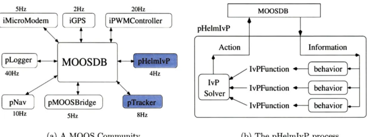
4-1 A MOOS community and the pHelmIvP process. . 4-2 The Orbit behavior. . . . .
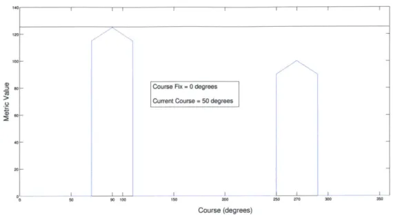
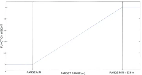
4-3 The ArrayTurn and ArrayAngle behaviors . . . . . 4-4 Objective Function for the ArrayTurn Behavior 4-5 Objective Function for the ArrayTurn Behavior 4-6 Objective Function for the ArrayAngle Behavior 4-7 Objective Function for the ArrayAngle Behavior 4-8 Dynamic Weighting for the ArrayAngle Behavior 4-9 Dynamic Weighting for the CloseRange Behavior 4-10 The Formation behavior .. . . . .
4-11 Formation Behavior Metric . . . .
. . . 5 3 . . . 5 5 . . . . 5 6 . . . . 5 6 . . . . 5 7 . . . . 5 8 . . . . 5 8 . . . . 5 9 . . . 6 0 . . . 6 1 . . . 6 1 2-1 2-2 2-3 2-4 3-1 3-2 3-3 3-4 3-5
5-1 5-2 5-3 5-4 5-5 5-6 5-7 5-8 5-9 5-10 6-1 6-2 6-3 6-4 6-5 6-6 6-7 6-8 6-9 6-10 6-11 6-12 6-13 6-14 6-15 6-16 6-17 6-18 6-19 6-20 6-21
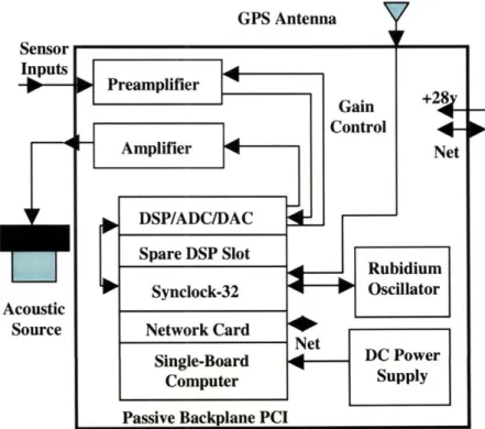
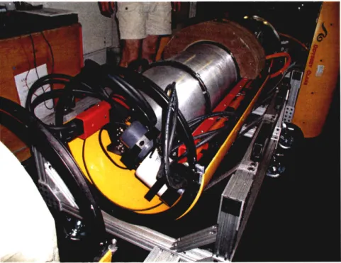
The logical sonar sensor . . . . AUVs with single and dual line arrays. . . . . Real-time sonar architecture . . . . Sonar pressure vessel in Odyssey-III payload section. . . Heron-4 DSP board and rubidium oscillator . . . . Sonar pressure vessel in Odyssey-III payload section. . . Online target detection with the sonar payload in active Spectrogram of a multi-static ping reception. . . . . Real-Time Target Bearings in FAF 05. . . . . Triangulation of acoustic source in FAF 05. . . . .
The track and classify mission scenario. . . . . Parameter observability based on sensor motion... Bearing simulator uncertainty .. . . . . The kayak-based autonomous surface craft. . . . . Platform motion for track and classify mission 1507. . . Track solution results for mission 1507. . . . .
Taruet loalia7.tion errnr fnr mkczi n 1!M7
Classification vehicle distance from target position estimate for mission 1507. Fisher information about x0 and x, for mission 1507. . . . .
Fisher information about X2 and X3 for mission 1507. . . . . Condition number of the Fisher information matrix for mission 1507. . . . . . Platform motion for track and classify mission 1444. . . . . Track solution results for mission 1444. . . . . Target localization error for mission 1444. . . . . Classification vehicle distance from target position estimate for mission 1444. Fisher information about x0 and x, for mission 1444. . . . .
Fisher information about x2 and X3 for mission 1444. . . . .
Condition number of the Fisher information matrix for mission 1444. . . . . . Platform motion for track and classify mission 1422. . . . . Track solution results for mission 1422. . . . . Target localization error for mission 1422. . . . .
14 64 66 67 68 70 71 75 76 77 78 MCM mode. . . . 80 . . . 84 . . . 87 . . . 88 . . . 90 . . . 91 . . . 92 . . . 92 . . . 93 . . . 93 . . . 94 . . . 96 . . . 97 . . . 98 . . . 98 . . . 99 . . . 99 . . . 100 . . . 102 . . . 103 . . . 104
.
.
.
.
.
6-22 Classification vehicle distance from target position estimate for mission 1422. 6-23 Fisher information about xo and x, for mission 1422. . . . .
6-24 Fisher information about x2 and X3 for mission 1422. .
6-25 Condition number of the Fisher information matrix for
The multi-sensor tracking Coordinate frame for 2D
7-3 A plot of coefficient C1.
7-4 A plot of coefficient C2 fo
7-5 A plot of coefficient C2 fo
7-6 A plot of coefficient C3.
7-7 A plot of coefficient C4.
7-8 Vehicle motion for missio 7-9 Target track results for m 7-10 Target track error for mis 7-11 Formation angle for missi 7-12 Target range for sensor p 7-13 Target range for sensor p
7-14 Speed estimate error for
7-15 Heading estimate error fo 7-16 Vehicle motion for missio 7-17 Target track results for m
7-18 Target track error for mis 7-19 Formation angle for missi 7-20 Target range for sensor p 7-21 Target range for sensor p 7-22 Speed estimate error for 7-23 Heading estimate error fo
7-24 Vehicle motion for missio
7-25 Target track results for mr 7-26 Target track error for mis
mission 1422. . . . 104 . 105 . 105 . 106 7-1 7-2 7-27 Formation angle for mission 1121. . . . 136
scenario. . . . 107 multi-sensor tracking. . . . 109 . . . 112 r 10m range. . . . . 112 r 20m range. . . . . 113 . . . 113 . . . 114 a 1448. . . . . 120 ission 1448. . . . . 121 sion 1448. . . . . 122 on 1448 . . . . 122
latform one for m ission 1448. . . . . 123
latform two for mission 1448. . . . . 123
fission 1448. . . . . 124 r mission 1448. . . . . 124 n 1144. . . . 127 ission 1144. . . . 128 sion 1144. . . . 129 on 1144. . . . 129
latform one for mission 1144. . . . 130
latform two for mission 1144. . . . 130
mission 1144. . . . 131
r m ission 1144. . . . 131
n 1121. . . . 134
ission 1121. . . . 135
7-28 Target range for sensor platform one for mission 1121. . . . 137
7-29 Target range for sensor platform two for mission 1121. . . . 137
7-30 Speed estimate error for mission 1121. . . . 138
7-31 Heading estimate error for mission 1121. . . . 138
8-1 Target tracking with N sensors. . . . 143
Chapter 1
Introduction
The oceans are of vital importance to life on earth. They are a key component of the earth's climate and weather, a significant source of food, a highway over which much of the world's com-merce travels, and an area which is vitally important for the national defense of many countries. The continental shelves hold vast reservoirs of energy, the deep ocean is thought to contain large deposits of important minerals, and many biologists believe there are deep sea organisms that hold great bio-pharmaceutical potential. And yet, more is probably known about the moon and other bodies in our solar system than is known about the oceans right here on earth.
A major reason for this lack of knowledge is the inhospitable nature of working in the ocean
which rivals or exceeds that of working in space. The crushing pressures aside, it is the physical nature of the fluid medium of the ocean which puts great limitations on our ability to sense what is there. A great many of the sensing technologies developed for use on land utilize either optical or radio frequency (RF) energy. In the ocean, electromagnetic energy at both RF and optical frequencies is highly attenuated. Light is also highly attenuated by the ocean's turbidity, caused by tiny suspended particles of plankton or sediment which scatter or absorb the light energy. The tendency of the ocean to absorb RF energy also hampers navigation of underwater sensor platforms. On land, systems such as GPS can be used for the precision location of sensors to within a few meters while no system as accurate as GPS has been developed for navigating underwater.
Due to the relatively high density of seawater, acoustic energy is propagated fairly well and its use is one of the key methods used for underwater sensing, navigation, and communications. Acoustic propagation in the ocean is, however, significantly affected by the ocean's physical
prop-erties. Attenuation of acoustic energy by seawater increases greatly with frequency, relegating most applications to the lower frequency bands or short distances. Boundary conditions caused
by the sea surface and sea bottom, the varying nature of the sound speed in the ocean caused
mainly by temperature variations, and the tendency of the sea surface and the sea bottom to reflect acoustic energy lead to many difficult problems when trying to propagate acoustic energy for sensing, communications, and navigation. Other types of sensors are useful in the ocean envi-ronment as well including chemical, biological, magnetic, electromagnetic, conductivity, pressure, and thermal sensors. Each type of sensor will have its own characteristics modulated by the ocean environment.
This work is motivated by an interest in a fundamental problem in sensor system design and operation for sensing in the ocean which is also applicable to sensing systems on land and in space. That is, how can one sense processes or the characteristics of processes which are intentionally or unintentionally difficult to sense using a single sensor which can only sample the process from a single spatial location at a given instant in time. In this work we define a process as the field generated by a physical event or phenomenon which can be sensed by a physical sensor such as those described previously. Many processes of interest are time-varying and not spatially isotropic and, therefore, either the process itself or some of its characteristics may not be observable from a single sensor platform. For other processes, spatially distributed sensors can add significant processing gain, reducing the sensing time and improving our estimates of the process parameters.
For example, in a passive sonar context, single sensor platforms can localize contacts using passive bearing information but require temporal diversity to do so while multiple, distributed bearing sensors can immediately form a solution. In an active sonar context, the scattering of acoustic energy off of objects of different shapes is highly directional and is dependent on the spatial relationship between the source, receiver, and target. It is impossible for a single sensor platform carrying both source and receiver to capture the full scattered field which is useful in classifying the target shape. Fig. 1-1(a) and 1-1(b) show the acoustic energy scattered from both a sphere and a cylinder insonified by the beam from a sonar. As can be seen, the scattering from the cylinder is highly directional with no significant energy backscattered toward the acoustic source while the scattering from the sphere is more spatially isotropic. A group of distributed sensors would be able to capture the spatial distribution of this scattering for use in classification. For sampling transient oceanographic phenomena such as frontal dynamics, the spatial sampling
Elba Inc 18 deg. 1 m buried sphere.
5
kHz F- 3000.0Hz SD- 5.Om RD- 5.2m -40 130 3-1 -20 -3 23 . 33 E E MRange (in) Rung. (in)
- (a) A sphere insonified at 3 kllz (b) A cylinder insonified at 5 kHz.
Figure 1-1: Acoustic insonification of a sphere and cylinder. As can be seen, the scattering from the cylinder is highly directional with no significant energy backscattered toward the acoustic source while the scattering from the sphere is more spatially isotropic.
resolution is related to the frequency content of the frontal process. Synoptic sampling coverage by multiple sensors can help avoid the temporal smearing that would occur in the data sampled by a single sensor platform. These examples, and numerous others, encompass a class of problems in marine sensing that can benefit from a multiple sensor approach.
In addition to being able to address the problems that cannot be solved using a single sensor, the use of mobile sensor platforms working in coordination
offers
several additional advantages. They may each have different payloads, sensors, and endurance capabilities. A network of small, inexpensive platforms withlow-performance
sensors may be able to use its spatial diversity to outperform systems using single, very expensive, high-performance sensors. The use of multiple platforms also may allow one platform to stay at the surface, with a higher bandwidth link to other robotic or human operated vehicles, while one or more other platforms operate under the surface at varying depths to optimize their sensor-oriented tasks. Network survivability is also enhanced as the loss of one or even possibly several inexpensive sensors can be absorbed with the redundancy inherent in such a network.The question then remains as to how we can accomplish this sensing of dynamic phenomena in the ocean with multiple sensors. What would such a system look
like
and how would it behave? As difficult as it is to sense phenomena in the ocean with a single sensor, coordinating multiplesensors seems a daunting challenge. We begin by attempting to define the requirements for such a system.
1.1
Requirements for a Marine Sampling Network
In this section we attempt to define some of the major requirements for a marine sampling network with the goal of being able to sense and characterize dynamic ocean phenomena both natural and man-made using multiple, cooperating sensor platforms. These requirements will lead us to define a system referred to as an autonomous oceanographic sampling network [1], described in greater detail in Chapter 2.
1.1.1
Mobility
One way to provide coverage of an area with multiple sensors would be to lay out a grid of fixed sensors all communicating back to a central data processing location. The grid spacing of the fixed sensors would be related to the process under observation. In fact, this method is used in many ocean sensing systems. For example, there is currently a network of ocean buoys that monitors parameters such as sea surface temperature, currents, conductivity, and ocean wave statistics for use in weather and hurricane forecasting systems. However, for many problems of interest, laying out a fine grid of fixed sensors is clearly impractical. This would be the case, for example, in applications where sensing must take place over a wide area with fine resolution or in deep water where the installation and maintenance costs of a sensor grid of the necessary size would be prohibitive. Fixed sensor systems are also not appropriate for applications where a temporary monitoring system is needed or in applications in which some action must be taken when certain conditions are sensed. The mobility of the sensor platforms is a key aspect of the adaptive sampling scenario, allowing dynamic optimization of the sensor locations with respect to the reduction in uncertainty of the process parameters we are attempting to estimate. A mobile sensor paradigm also allows resource optimization in scenarios where specialized sensors on mobile platforms can be brought to bear on a problem when more generalized sensors have made initial determinations. For example, in a mine countermeasures scenario, a network of low-frequency sonar platforms could localize a potential target and then call in additional sensor platforms with chemical sensors or sidescan sonars to gather additional information. In military
target tracking applications, kill vehicles could be vectored to a target by a network of sensors which are simultaneously tracking and classifying the target.
1.1.2
Adaptivity
In the absence of a fine grid of sensors which can spatially sample a phenomenon simultaneously from multiple points, the sensors must not only be mobile but they must also be able to au-tonomously adapt their motion in real time according to the sampled data. This requires tight coordination between the sensors and the vehicle control. Given that a sensor platform may carry multiple heterogeneous sensors, this requires a sensor integration model that abstracts sensory data for use by the sensor platform control system. In Chapter 5 we describe a sensor integra-tion model that makes use of the concept of a logical sensor that abstracts away the details of the physical sensor. In Chapters 6 and 7 we use this model in two experiments using simulated bearing sensors where the output of the logical sensor is a target track.
Once a sensor platform receives sensory data, the platform control system must use this en-vironmental state data to maneuver. Typically, our goal will be to maneuver the platform in such a way as to gain additional information about the process we are observing. This requires some sort of mapping between the environmental state data and the vehicle control parameters (rudder, elevator, speed, etc.) In Chapter 3, two major methods for doing this are described, the world model-based and the behavior-based methodologies. In the world model-based method-ology, one large model is used to map the environmental state data to the control parameters. However, the very large state space inherent to a marine vehicle operating in any reasonably complex application is prohibitive for such an approach in my view. A sensor platform may be dealing not only with sensor data from an application specific sensor like an acoustic array but also with tasks like obstacle avoidance, path planning, and navigation. A direct mapping of sensor states to vehicle control variables is infeasible with such a large state space. A behavior-based control system, in contrast, uses a number of modular computing units termed "behaviors", all operating in parallel, to decide the vehicle's course of action during each control cycle. During a control cycle, each behavior will use the current sensor state data to compute its opinion on the next course of action. For example, each behavior may output its preferred course, speed, and depth for the vehicle. The issue then arises about how to select the preferred action when multiple behaviors disagree. One method would be to simply pick the output of the behavior
with the highest priority. This scheme was used by Brooks in his original layered control method [2]. This method, however, does not allow for the possibility of compromise between the preferred actions of different behaviors. In this work, we use a method for behavior-based control in which each behavior outputs its preferred action as an objective function over the vehicle control vari-ables. During each control cycle, the preferred action is decided by performing a multi-function optimization over all of the objective functions. The optimization is performed using the In-terval Programming Method (IvP) developed by Benjamin [3] to perform the optimization in a computationally efficient manner. This method is more fully described in Chapter 3.
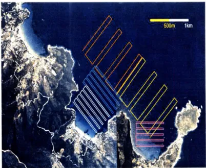
The current state of the art in sampling with underwater vehicles is primarily limited to the use of non-adaptive, preplanned sampling missions where the collected data is stored for offline retrieval and analysis. Fig. 1-2 shows typical preplanned sampling paths for an autonomous underwater vehicle (AUV) used to sample environmental data off the coast of Elba, Italy. The
AUV has no capability to react to data received from its environmental sensors other than the
navigation sensors which keep it on its preplanned course.
Figure 1-2: Several non-adaptive sampling paths for an AUV operating off the coast of Elba, Italy. Data is stored for offline retrieval. The sensor platform has no capability to react to the sensed data.
1.1.3
Communications
It seems an obvious conclusion that in order for multiple sensors to coordinate their actions and share state information, they must be able to communicate. This is easier said than done in the ocean environment however. On land, RF or fiber optic communications systems are capable of transmitting information on the order of megabits per second or greater. In the ocean, where RF energy is unusable over any distance and acoustic data transmission must be used, data transmission rates are orders of magnitude lower due to the propagation constraints imposed by the ocean environment (in particular, the relatively slow phase speed of acoustic waves). This directly impacts the amount of information that can be shared in a marine network and the types of network connectivity that can be used. Since all sensor platforms must share the same acoustic channel, this may also limit the number of platforms that can be active.
The amount of bandwidth needed in a cooperative sensor network is related to the sampling requirements of the process under observation. Processes with high frequency content require correspondingly high bandwidth. For processes with low frequency content, bandwidth require-ments may be traded off for an increased sampling period. This issue is complicated by the fact that the acoustic channel may also be used simultaneously by sensors and navigation systems. Along with sensor platform navigation, a robust communications capability is one of the two critical supporting technologies needed to implement an effective sensor network.
1.1.4
Cooperation
While coordinated marine vehicles have their advantages, they present challenges in their joint control to reach their combined potential. Inter-vehicle communication is limited in bandwidth and carefully allocated. Any kind of central continuous control is likely infeasible. In multi-vehicle joint exercises involved with sensing dynamic phenomena, it may not be practical or effective to think in terms of a single vehicle state space to which proper actions can be assigned a priori. In Chapter 3 we describe a behavior-based control approach where a number of behaviors operating in parallel use the sensed environmental state data to maneuver the sensor platform. In this work, we use an approach to cooperation in which some of the behaviors on the sensor platforms are specifically designed to use state data from other sensor platforms in order to form a decision on preferred platform maneuvers. This state data is shared via the communications network. This is a form of highly decentralized cooperative control in which there is no central planner
dictating actions to the sensor platforms. This in keeping with the spirit of behavior-based control in which there is a tight coupling between control and the perceived environment. This scheme has an obvious advantage with respect to network survivability in that any network with central planning is vulnerable to to the loss of the planner, whether that function resides on another sensor platform or on the surface. A network with decentralized control is more able to gracefully degrade with the loss of particular sensor nodes. More details on cooperation are discussed in Chapter 3.
1.1.5
Sensor Fusion
Data fusion is the synergistic combination of information from different sources such as sensors in order to provide a better understanding of the state of the world [4]. In our marine sensor network application, sensor data from multiple, distributed sensor platforms must be combined. These sensors may be heterogeneous and may have different resolutions. For example, data from both range and bearing sensors may need to be combined in surveillance and target tracking applications. In the target tracking example with distributed sensors discussed in Chapter 7, two independent bearing observations from distributed sensor platforms must be combined to estimate a target track. A significant issue in fusing data from multiple sources is in determining that distributed measurements correspond to the same environmental feature [4]. This is known as the data association problem. This issue arises for example in tracking applications where multiple targets may be present.
In order to properly fuse data from multiple sources and possibly heterogeneous sensors, accurate models of the process we want to observe and our sensor characteristics are imperative. Accurate process models allow us to derive the proper sensor platform behaviors given the state of the environment. These models must view the process from a probabilistic standpoint. It is not good enough to provide an estimate of a process parameter without also providing a notion of the uncertainty associated with the estimate. This also allows accurate simulation of adaptive sensor platform operation. The uncertainty of our estimates is related to a number of factors but primarily on the uncertainty of our sensor measurements, the uncertainty of the spatial location where the measurement was taken, and the time the measurement was taken. The uncertainty of the sensor measurements can be dealt with by having an accurate sensor model. The uncertainty in the measurement time can be easily dealt with by precision time synchronization between the
sensor platforms. A method for doing this is discussed in Chapter 5. As discussed previously, platform navigation is one of the two critical supporting technologies required in a sensor network. At the very least, the navigation uncertainty must remain bounded over the time period the sensor platform is in operation. If the navigation uncertainty grows over time this will introduce a growing uncertainty in our sensor measurements and hence in our estimates. This is clearly undesirable. A number of techniques for sensor platform navigation are discussed in Chapter 2.
1.2
Other Adaptive Sampling Work
A number of researchers and organizations have been conducting research into adaptive sampling
systems and algorithms. The Woods Hole Oceanographic Institution has been investigating the use of AUVs for chemical plume tracing [5][6] and hydrothermal vent localization [7][8][9]. The Autonomous Undersea Systems Institute has been investigating adaptive sampling algorithms for oceanographic phenomena using both single and multiple cooperating AUVs [10][11]. Princeton University has been undertaken a major investigation into adaptive sampling with fleets of gliders for autonomous oceanographic sampling networks [12][13][14]. MIT Sea Grant has investigated the adaptive use of AUVs for long-term observation of ocean eddies [15]. A number of other investigators have researched generic techniques for adaptive sampling [16][17].
1.3
Preview of Results
In this work these challenges are addressed by presenting a novel architecture consisting of a network of sensor platforms each with an intelligent sensor supplying high-level environmental state data to a new type of behavior-based control system that is more suited to reactive control with multiple constraints than previous behavior-based implementations. Experimental results are presented for a 2-D target tracking application in which fully autonomous surface craft using simulated bearing sensors acquire and track a moving target in open water. In the first example, a single sensor vehicle adaptively tracks a target while simultaneously relaying the estimated track to a second vehicle acting as a classification platform. In the second example, two spatially distributed sensor vehicles adaptively track a moving target by fusing their sensor information to form a single target track estimate. In both cases the goal is to adapt the platform motion to minimize the uncertainty of the target track parameter estimates. The link between the sensor
platform motion and the target track estimate uncertainty is fully derived and this information is used to develop the behaviors for the sensor platform control system. The experimental results will clearly illustrate the significant processing gain that spatially distributed sensors can achieve over a single sensor when observing a dynamic phenomenon of interest. Behavior-based control is also shown as a viable method for dealing with uncertainty in complex control situations in marine sensor networks.
1.4
Thesis Organization
This thesis is organized in the following manner:
Chapter 2: Autonomous Oceanographic Sampling Networks. This chapter describes the ideas and the work to date regarding marine sensor networks originally envisioned in
[1].
Chapter 3: Behavior-based Control of Autonomous Platforms. This chapter compares and contrasts two prevailing methods for robotic control, the world-model approach and the behavior-based approach as well as the various methods for action selection in behavior-behavior-based approaches. Here we describe the use of objective functions for action selection and the Interval Programming Method for computing the consensus action.
Chapter
4:
The MOOS-IvP Autonomy Architecture. This chapter describes the MOOS-IvP autonomy architecture used on the autonomous sensor platforms.Chapter 5: An Intelligent Acoustic Sensor. This chapter describes the concept of a logical sensor and the design of a real logical sensor for an AUV for use in a marine sensor network.
Chapter 6: Example One: Adaptive Track and Classify. This chapter describes an adaptive tracking experiment involving a tracking vehicle with a simulated bearing sensor which tracks a target and networks the target track estimate to another vehicle acting as a vehicle with a classification sensor which closes range with the target position estimate.
Chapter 7: Example Two: Adaptive Tracking with Multiple Sensors. This chapter describes an adaptive tracking experiment using two autonomous surface craft with simulated bearing sensors which cooperatively track a moving target.
Chapter 8: Summary and Conclusions. This chapter summarizes the original contributions of the thesis and gives an overview of future work.
Chapter 2
Autonomous Oceanographic
Sampling Networks
By 1993, advances in robotics, communications, and sensor technology were reaching a
crit-ical mass that allowed, for the first time, the possibility of remote, unattended sampling of oceanic processes over wide areas. Autonomous underwater vehicles carrying a variety of sen-sors held promise for adaptive sampling of oceanographic processes and coupled ocean observa-tion/modeling systems [1] [18]. Understandably, this possibility elicited excitement among not only physical scientists who wanted to gain a better understanding of oceanic processes but also among forward-thinking members of the defense establishment who saw a number of advantages. First, the understanding of basic oceanic processes and characteristics is vital in almost every aspect of conducting undersea warfare including, but not limited to, undersea communications and sonar performance. Second, having the capability of deploying undersea sensor networks opens up interesting possibilities not only for coastline defense but also for offensive operations. The primary motivation for the autonomous oceanographic sampling network (AOSN) concept originally developed in [1] by Curtin and Bellingham is that current methods for sampling under-sea processes are limited and these limitations are inhibiting our understanding of a wide range of ocean science problems. They argue that the measurement of temporal and spatial gradients in the ocean far exceeding current capabilities are needed to validate current models of oceanic processes. Some examples of the types of problems that would benefit from new methods are given as the mechanisms of frontal dynamics, surface dynamics, stratified turbulence, cross-shelf transport, deep convection, and sea ice mass balance. They argue that the current sampling done
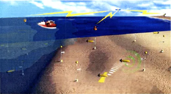
Figure 2-1: An Autonomous Oceanographic Sampling Network. Autonomous oceano-graphic sampling networks consist of a distributed system of fixed and mobile sensors networked together by communications nodes.
from ships, moorings, and floats only produces quasi-synoptic two-dimensional sections through evolving fields and that sparse sampling can introduce problems with temporal and spatial alias-ing. The conclusion drawn by the authors is that a robust, distributed, autonomous system with low unit cost is necessary to affordably meet the requirements of sampling with long durations and high resolution. It is clear that such a system meets many of the requirements for marine sensor networks discussed in Chapter 1. In this chapter we will discuss the AOSN system concept and enabling technologies for AOSN implementation and review much of the work to date.
2.1
System Concept
An AOSN system consists of a distributed network of fixed and mobile sensors deployed in an area of interest. Nodes in this network are comprised of moorings or buoys equipped with acoustic beacons, acoustic communications modems, fixed sensors, power sources, and docking facilities for autonomous underwater vehicles (AUVs) and surface craft. A depiction of this concept is given in Fig. 2. The sensor platforms in this network can either be propeller-driven or buoyancy-driven (e.g gliders) underwater vehicles or surface craft. The AUVs traverse the network collecting data samples using a variety of sensors. Key observations can be transmitted in real-time to one of the network nodes while full data transfer occurs during docking with specialized buoys
designed to recharge the sensor platform batteries. Autonomous surface craft can be used as mobile navigation or communications nodes or they can be used to carry specialized sensors like sidescan sonars, for example. In oceanographic process sampling scenarios, acoustic transmission loss along the inter-nodal paths can be used to detect evolving fronts. A network controller then dispatches autonomous sensor platforms to the frontal region where they sample the evolving front and adaptively alter their motion in response to both the locally-sensed gradients and the global data set. In surveillance applications, autonomous sensor platforms can be programmed to patrol in distributed orbits waiting for a target to appear within sensor range. Upon target detection, these platforms can adaptively track the target and relay the track information to the communications network. Other sensor platforms with specialized classification sensors can then be vectored toward the target. One of the most important advantages of the sensor network approach to sampling is its ability to support cooperative sampling in which two or more sensor platforms maneuver themselves to increase their information about a process by exchanging state information. This allows processes to be sampled which would otherwise be difficult or impossible for a single sensor to sample.
The key advantages claimed for the AOSN concept are synoptic volume coverage, adaptive sampling, flexible control, energy management, and robustness to component failure. The authors of [1] assert that the practicality of the AOSN concept as described depends on the number of AUVs required, the type of AUV, and the performance of acoustic navigation and telemetry. Both the type and numbers of AUVs needed will heavily impact the cost of the network which, in the final analysis, is usually the deciding factor on the practicality of a system.
2.1.1
Number of Sensor Platforms Required.
Any synoptic survey system must be able to sample a process at a faster rate than significant changes occur in the structure if temporal aliasing is to be avoided. In order to avoid spatial aliasing, minimum spatial resolutions must also be maintained. These minimum sampling re-quirements of course drive the requirement for the number of vehicles needed to provide coverage of an area of ocean of a particular size. However, since autonomous sensor platforms have limited energy storage and the power required to operate a survey platform is heavily related to its speed, equations for the total energy required and the optimum number of vehicles required to survey an area of ocean with a particular resolution can be derived. These equations, derived in [1], show
that the optimum number of vehicles for oceanographic sampling varies with the area of the sur-vey region and inversely with the required resolution and completion time as would be intuitively expected. There is also a weak increase in optimal vehicle number as vehicle size increases and hotel load decreases. As noted in the text, increasing the number of survey vehicles would allow the use of smaller (and presumably cheaper) vehicles because energy storage requirements are a major factor driving vehicle size.
Although the authors of [1] derive the optimum number of survey vehicles needed for a given survey in terms of minimum energy usage, it does not consider impact of using multiple vehicles on survey error or quantify the impact of adaptive sampling strategies. This situation was corrected in Bellingham and Willcox's 1996 paper [19]. In this paper, the impact on survey error of using multiple survey vehicles is computed for statistical ocean processes. The results show that while changing the physical parameters of the sensor platform (e.g. reducing hotel load) results in a mild increase in survey efficiency, the largest gains in error reduction come from using multiple vehicles and/or using adaptive sampling strategies. The is largely the result of an effective reduction in survey area per sensor platform. A paper describing the derivation of performance metrics for oceanographic surveys with AUVs is given in [20].
2.1.2
Sensor Platform Type
A network of many low-cost, light-weight underwater vehicles (see Fig. 2.1.2 and Fig. 2.1.2 [21])
is preferable to using a few, relatively expensive vehicles. Large vehicles are costly to build and operate while very small vehicles have difficulty integrating inexpensive sensors and computer hardware. In [1] the claim is made that moderate sized vehicles (1 - 3 m long and 0.2 m to 0.8 m in diameter) are optimal due to their high maneuverability, high thrust to mass ratios, low
cost, and ability to carry oceanographic sensors over ranges of at least hundreds of kilometers. Buoyancy driven vehicles (see Fig. 2.1.2) are also indicated for some applications, primarily observation of large-scale ocean processes. These vehicles are very power efficient but have low maneuverability and speed. Gliders could theoretically remain on station for periods of weeks to months but are power limited which tends to reduce the number of sensors that can be carried.
Since [1] was written, autonomous surface (see Fig. 6-4) have also emerged as a candidate sensor platform for marine sensor networks. These vehicles bring a number of advantages to the AOSN concept including the ability to carry a variety of sensors, but one of their greatest
Figure 2-2: An Odyssey-III AUV. This survey-class AUV is able to carry a wide variety of scientific sensors and is able to operate underwater unattended for long periods of time.
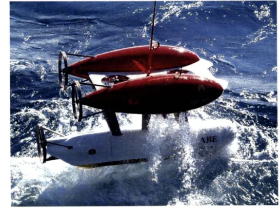
Figure 2-3: The Autonomous Benthic Explorer (ABE). ABE can survey the ocean floor at depths up to 5500 m carrying a variety of sensors such as cameras, sonar, and chemical sensors. ABE is operated by the Woods Hole Oceanographic Instituion.
advantages is their ability to utilize the global positioning system. This allows autonomous surface craft to be able to act as mobile navigation and communications nodes within the network. This holds the promise for developing adaptively reconfigurable communications and navigation nodes. In particular, a reconfigurable communications network would be able to sense the local communications environment and be able to reconfigure their positions autonomously.
Figure 2-4: The Slocum glider. Gliders are very useful for sampling wide area oceanic phenomena. They are able to operate underwater for very long periods of time due to their use of thermal gradients in the ocean for their motion.
2.1.3
Acoustic Communications and Navigation.
In the AOSN concept, acoustic communications is necessary for communication between network nodes, between mobile sensor platforms and network nodes, and also possibly between remote fixed sensors and network nodes. The authors of [11 envision a sort of underwater "cellular telephone" system in which the network nodes perform much the same as current cellular base stations do. Data transfer rates for state-of-the-art acoustic modems (in 1994) are given as
10 kbit/s at 10 km and 3 kbit/s at 90 km. The authors claim that these data rates enable
both the efficient telemetry of commands to the sensor platforms but also the transfer of large amounts of recorded data from the sensor platforms to the network nodes. A key issue here is energy efficiency, measured in kbit/joule per kilometer. While efficiencies in the range of
1 kbit/joule/km to 100 kbit/joule/km are manageable with sensor platforms and network nodes,
careful trade-offs must be examined for remote sensors which may have to run unattended for months or years on battery power.
Substantial advances have been made in underwater acoustic communications since 1993. Some of these advances are described in [22] and [23]. Advances have been made both in terms of energy efficiency and in data rates. Advances in underwater navigation are less clear. The widespread use of GPS has made it easier to precisely locate surface buoys for long and short-baseline navigation systems but those networks are still plagued by the same poor performance at long ranges. Large strides have also been made in inertial navigation systems small enough to be used in AUVs (e.g. laser ring gyro systems) but there is still no way to get around the increasing error with distance problem. Theoretical advances have been made in stochastic mapping approaches such as concurrent mapping and localization [24] and other feature-based navigation techniques [25] but no practical system has yet been fielded. There is some promise in the use of autonomous surface craft as mobile navigation nodes in marine sensor networks, leveraging the surface craft's ability to position itself with GPS and its ability to communicate with underwater platforms via acoustic modem. Precise time synchronization between sensor platforms may allow precise inter-vehicle ranging simultaneous with acoustic communications.
2.1.4
Vehicle cost.
One of the most critical assertions made in [1] is that AUV costs will be driven lower by economies of scale as computer aided manufacturing and advanced materials combine with volume manu-facturing. As noted earlier, the number of AUVs required is related to the area of ocean to be surveyed as well as the spatial sampling resolution and required survey time. In order to be able to achieve high-resolution surveys of any reasonable size, AUV costs must be as low as possible. The authors sate that a reasonable cost objective is between $10K and $50K per vehicle.
Even though one of the critical assumptions was that low-cost manufacturing techniques and volume production would lower the cost of AUVs, this has not been the case. If anything, AUV survey vehicles are even more expensive than in 1993. For the most part this seems due to the fact that most AUVs are still hand-made research vehicles. The authors state that the optimum cost for AUVs is in the neighborhood of $10K to $20K while current prices can run 10 to 50 times that cost.
2.2
Enabling Technologies.
In [1], the authors assert that a number of "high leverage" technologies have the capability to substantially advance AOSN capabilities. One of these is intelligent software control of AUVs.
A full implementation of the AOSN concept requires that AUVs be able to implement adaptive
sampling including the ability to coordinate/cooperate with multiple vehicles in order to optimize the sampling strategies with regard to variables such as time, power consumption and perhaps, most importantly, survey error. The optimization of AUV control strategies is highly dependent on models of the process to be observed. This issue, of course, is the topic of this thesis.
Energy storage and power management of the AUVs is given as another key enabling tech-nology. The survey range of an AUV is determined by its energy storage capacity and its power usage. Obviously, an increase in the energy density of energy storage systems has the capacity to extend AUV range and/or reduce vehicle size. An increase in propulsion efficiency or a decrease in the required hotel load would also have the same effect.
While a number of theoretical attempts at control strategies for multiple AUV systems and adaptive sampling have been made, no great leaps in progress have been made in this area. One of the more interesting attempts is described in [141 in which a virual bodies and artificial potentials strategy was used to control adaptive sampling among multiple vehicles in an AOSN experiment. This is an example of an adaptive control method known as the world-model or "sense-plan-act" model discussed in Chapter 3.
Progress in energy storage has also been amazingly slow. While some attempts have been made to use fuel-cell technology to power AUVs, most AUVs continue to use conventional battery technology. Current state-of-the-art batteries for AUVs use the same lithium-polymer battery technology as found in laptop computers.
2.3
Historical Developments
2.3.1
The AOSN Project
The AOSN project was begun with the long-term goal to create and demonstrate a reactive survey system, capable of long-term unattended deployments in harsh environments. Sponsored
by the Office of Naval Research, AOSN was a collaboration between the Massachusetts Institute
Northeastern University. The main thrust of the project was to develop both AUV technology and AOSN network infrastructure technology including acoustic communications [23] and vehicle docking technology [26] as well as the investigation of operational techniques. There were two major AOSN experiments, the Haro Strait experiment and the Labrador Sea experiment.
Haro Strait
The goal of the Haro Strait AOSN experiment (formally the Ocean Frontal Dynamics Primer Initiative) [27] [18] was to use advances in ocean modeling and AUV technology to study tidal mixing processes in the Haro Strait which lies between the San Juan Islands and Vancouver Island off of British Columbia. The main technical goals of the experiment were adaptive sampling, co-ordinated platform operations, and communications. More than 60 AUV runs were accomplished in an attempt to localize and characterize the strong tidal fronts as they moved through the strait. The experiment was a jointly conducted between MIT, the Woods Hole Oceanographic Institution, the Institute for Oceanographic Science in British Columbia, Harvard University, and the University of Victoria.
Labrador Sea
The goal of the Labrador Sea AOSN deployment was to observe convection plumes in a responsive, repetitive manner by providing a long-term unattended deployment capability [18]. This was the first attempt at long-term deployment of AUVs and gliders in an AOSN and used moorings and buoys in addition to the sensor platforms for RF communications and unattended recharging of vehicle batteries. Communications moorings were used to relay commands to the sensor platforms as well as receive science data from the platforms when the platforms were docked.
2.3.2
The AOSN-II Project
AOSN-II is an ONR-sponsored, multi-institutional, collaborative research program with the cen-tral objective to quantify the gain in predictive skill for principal circulation trajectories, trans-port at critical points and near-shore bioluminescence potential in Monterey Bay as a function of model-guided,remote adaptive sampling using a network of AUVs. A partial AOSN implementa-tion, AOSN-II will use a fleet of Slocum gliders [28] to adaptively sample the oceanic processes in Monterey Bay. The key research goals of the experiment are a focus on adaptive sampling and
the opportunity to use the glider network as a reconfigurable, mobile sensor array. A major test of the AOSN-II concept using Slocum gliders was performed in 2003 [14].
2.3.3
The NEPTUNE Project
The NEPTUNE project [29] [22] is a perfect example of the implementation of a prototypical
AOSN. The goal of the NEPTUNE project is to establish a regional ocean observatory in the
Pacific Ocean off the northeast coast of the United States. A 3000 km network of fiber optic cables will encircle and cross the Juan de Fuca tectonic plate, an area of nearly 500 km by 1000 km in size. Approximately 25 experimental sites will be established at nodes along the cable. Each experimental site will be instrumented to sample physical, chemical, and biological parameters using a combination of fixed and mobile sensors interconnected by an acoustic network. The AUVs will reside at depth at each node where they will recharge and respond to real-time events such as underwater volcanic eruptions. Real-time data and command and control capabilities will be available via the Internet. Costing an estimated $250M to develop and operate over the first five years, NEPTUNE will be partially operational by 2007.
2.4 Relevance of AOSN to this Thesis
The focus of this thesis is a fundamental problem in sensor design and operation for real-time observation of ocean processes with mobile sensor platforms. This problem relates to the ob-servation of processes which intentionally or unintentionally are difficult to view using a single sensor platform and which require the use of multiple sensor platforms, each of which can sense the process from a different "viewpoint." Necessarily, this requires close coordination between the sensor platforms and the ability of the platforms to adapt their sampling (sensing) strategy to information received and processed in real-time. The goal is to be able to use numbers of small, inexpensive sensor platforms for this task. One of the applications of great interest examined in this thesis is the tracking of acoustic targets using passive (bearings-only) sensory data. Chapters
6 and 7 give experimental examples of adaptive, networked target tracking with both single and
multiple sensor platforms.
One of the features of the AOSN paradigm that is ideally suited for the target search and identification problem is its sensor-adaptive nature, i.e. the pre-planned movement of the sensors (the AUVs in this case) can change according to the nature of their sensor readings. This allows