HAL Id: hal-03176536
https://hal.archives-ouvertes.fr/hal-03176536
Submitted on 22 Mar 2021HAL is a multi-disciplinary open access archive for the deposit and dissemination of sci-entific research documents, whether they are pub-lished or not. The documents may come from teaching and research institutions in France or abroad, or from public or private research centers.
L’archive ouverte pluridisciplinaire HAL, est destinée au dépôt et à la diffusion de documents scientifiques de niveau recherche, publiés ou non, émanant des établissements d’enseignement et de recherche français ou étrangers, des laboratoires publics ou privés.
CONCRETE IMPREGNATED WITH CEMENT AND
CAMEROONIAN CHARCOAL AS COARSE
LIGHTWEIGHT AGGREGATE
Théodore Gautier L J Bikoko, Jean Tchamba, Valentine Katte, Sofiane
Amziane, Felix Ndubisi Okonta, Thomas Tamo
To cite this version:
Théodore Gautier L J Bikoko, Jean Tchamba, Valentine Katte, Sofiane Amziane, Felix Ndu-bisi Okonta, et al.. CHARACTERIZATION OF LIGHTWEIGHT CONCRETE IMPREGNATED WITH CEMENT AND CAMEROONIAN CHARCOAL AS COARSE LIGHTWEIGHT AGGRE-GATE. International Journal of Advanced Research in Engineering and Technology, IAME, 2021, �10.34218/IJARET.12.3.2021.033�. �hal-03176536�
Available online at http://www.iaeme.com/IJARET/issues.asp?JType=IJARET&VType=12&IType=3 ISSN Print: 0976-6480and ISSN Online: 0976-6499
DOI: 10.34218/IJARET.12.3.2021.033 © IAEME Publication Scopus Indexed
CHARACTERIZATION OF LIGHTWEIGHT
CONCRETE IMPREGNATED WITH CEMENT
AND CAMEROONIAN CHARCOAL AS COARSE
LIGHTWEIGHT AGGREGATE
Théodore Gautier L J Bikoko*
Department of Civil Engineering Science, University of Johannesburg Auckland Park, Johannesburg, South Africa
Jean Claude Tchamba
Department of Civil Engineering, ENSET, University of Douala, Douala, Cameroon
Valentine Yato Katte
Department of Civil Engineering and Forestry Techniques
Higher Technical Teachers'Training College, University of Bamenda, Cameroon
Sofiane Amziane
Department of Civil Engineering, Blaise Pascal University (University Clermont Auvergne, Polytech Clermont-Ferrand), France
Felix Ndubisi Okonta
Department of Civil Engineering Science, University of Johannesburg, Auckland Park, Johannesburg, South Africa
Thomas Tatietse Tamo
Department of Civil Engineering, National Advanced School of Engineering University of Yaoundé I, Yaoundé, Cameroon
*Corresponding Author
ABSTRACT
This paper reports the results of a study on the formulation and characterization of lightweight concrete made with Cameroonian charcoal as coarse lightweight aggregate. Lightweight concrete is an old material and has been known around the world for over a quarter of a century. They are experiencing a renewed interest, which seems quite deserved because of their properties; it belongs to the family of special concretes. These characteristics suggest new applications. Lightweight concrete has low density than conventional concrete and the use of concrete of low density
contributes to the reduction of the weight of the elements built with this concrete and subsequently the dimensions of the load-bearing elements, resulting in the reduction of the forces transmitted to the ground by the foundations, and consequently the dimensions of the latter, which allows the construction on soils of low bearing capacity. In this study, we first determined the characteristics of the constituent materials of our lightweight concretes, and then we formulated our lightweight concretes through two distinct formulation methods, namely the Dreux-Gorisse method and the progressive introduction method. Following these formulations, we have made several samples of lightweight concretes. Using laboratory tests, we have determined some of the physical and mechanical characteristics of these lightweight concrete samples. The results showed that when the charcoal content increases in the concrete, its water absorption rate increases. This is accompanied by a decrease of the mechanical strength. The mechanical strength of concrete evolves with time. The tensile strength is about 5 times lower than the compressive strength. The lightweight concretes developed are applicable for masonry bricks production in accordance with SANS 1215, NF DTU 20-1 (20-1999), NF P 20-14-304 (20-1983), NF EN 7720-1-3 (2020-120-1) and NF EN 7720-1-3 / CN (2020-12)
Key words: Lightweight concrete, Cameroonian charcoal, mechanical strength, water
absorption rate and formulation.
Cite this Article: Théodore Gautier L. J. Bikoko, Jean Claude Tchamba, Valentine Yato
Katte, Sofiane Amziane, Felix Ndubisi Okonta and Thomas Tatietse Tamo, Characterization of Lightweight Concrete Impregnated with Cement and Cameroonian Charcoal as Coarse Lightweight Aggregate, International Journal of Advanced
Research in Engineering and Technology (IJARET), 12(3), 2021, pp. 330-365.
http://www.iaeme.com/IJARET/issues.asp?JType=IJARET&VType=12&IType=3
1. INTRODUCTION
Concrete can be considered no more than a mixture of cement as a binder, water, aggregate (fine and coarse) and admixtures (chemicals or minerals or both) [1,2]. Admixtures are used to improve the performance of the concrete. This could include adjusting setting time or hardening, modifying the properties of the hardened concrete, reducing water required in the concrete, reducing the cost of concrete construction [3]. The concrete usage in France each year is 60 million of m3 on average of 1 m3 per capita. Among its constituents, the aggregates occupy up to 75% of concrete volume. Today, concrete remains the manufactured construction material more known and more utilized in the world, whether in the construction of the buildings, bridges, viaducts, airports, roads, railways, tunnels, stadia and other civil engineering infrastructures. Concrete is the second most used substance on earth after water. Its advantages include: high compressive strength, good workability, good durability properties (resistant to freezing, chemical resistant, wear resistant, low permeability, resistant to alkali-silica reaction and so on), easy handling and molding, easy transportation from the place of mixing to place of casting before initial set takes place, longevity, resilience and its disadvantages include: low tensile strength, low thermal and acoustics insulation, its heaviness. In order to remedy or mitigate or overcome these weaknesses or disadvantages or limitations of concrete, for example to reduce or decrease its heaviness or its density or its weight and make the buildings lighter, another variety of concrete called lightweight concrete appeared at the beginning of the 20th century in the developed countries of Europe such as France, Germany and the USA and of Asia such as Japan, former USSR and other countries [4]. In the field of construction, the reduction of the self-weight of lightweight concrete appears technically and economically interesting, for the restoration of old infrastructures or for the construction of new
infrastructures [4]. The reduction of the density of lightweight concrete induces lower dead load to concrete structures, consequently saving on transportation and handling costs. Additionally, the lower density of lightweight concrete exhibits superior heat and thermal insulation, fire resistance as well as reducing risk of earthquake damage [5]. According to [6], lightweight aggregates today are present in various fields such as the buildings (precast concretes and ready-mixed concrete), public works (as backfilling materials). Some are not very resistant even reliable while others are resistant and hard. The search for new lightweight concretes always continues [7, 8]. A study conducted by [9] informs us that the mechanical characteristics of lightweight concretes strongly depend on the properties and proportions of aggregates present in the formulation. Lightweight concretes are mixtures whose majorities of the constituents are less heavier than the normal concrete [7]. The International Union of Laboratories and Experts in Construction Materials, Systems and Structures (RILEM) lightweight concrete commission quoted by [10] proposes to define lightweight concretes as concretes with a dry density of less than 1800 Kg/m3. Other authors adopt a little different definitions: the American Concrete
Institute (ACI) limits the bulk density of lightweight concrete to 1800 Kg/m3 after air drying for 28 days. The German standard, DIN 1042 (1972) limits the apparent density of a lightweight concrete to 2000 Kg/m³. The Eurocode 2 limits the bulk density of lightweight concrete to 2200 Kg/m3 [11]. Compared to conventional concrete whose density lies between 2200 and 2600 Kg/m³, lightweight concretes have a lower density [12]. The Canadian Portland Cement Association (PCA) defines structural lightweight concrete as having a compressive strength at 28 days higher than 15 MPa whose density is lower than 1850kg/m³[12,13]. The heavy materials found in conventional concrete such as gravels can be replaced by lightweight aggregates as the polystyrene beads, expanded polystyrene [14] for the problems of thermal isolation or acoustics, schist, aggregates of cork [15,16], ashes of rice balls [17], wood chips [18,19], expanded clays and shales, fly ash, pumice, slag, perlite, expanded glass, vermiculite, pumice, oil palm shell, coconut shell, tuff, zeolite, scoria, volcanic cinders, vesiculated lava, amongst others. So far, no information or data is available from this study area on concrete made with charcoal as coarse lightweight aggregate. Within the framework of this work, the density of the concrete represents one of the most important characteristics. The reduction of the density made possible while changing the type of aggregate and while varying the proportions of the various constituents is the principal stake of this study. This article proposes the formulation and characterization of lightweight concrete impregnated with cement and Cameroonian charcoal as coarse lightweight aggregate obtained from the eucalyptus plant in North West Region, Bamenda, Cameroon.
2. LITERATURE REVIEW
The first lightweight concretes have been made with Grecian and Italian pumice as the lightweight aggregates. Hydrated lime was used as a binding material. Studies related to
lightweight concrete have been conducted since the beginning of the 20th century and in 1923, Mr. Dan Servey manufactured the first lightweight concrete masonry units.
Kitouni and Houari [20] studied the physical performance of concrete formulated with substitution of 30% of coarse aggregates by Algerian limestone dust. The study involved preparation of lightweight concrete based on CEM II/ A (CPJ 42.5), sand and crushed gravel of class 0/3 mm and 3/8 mm, respectively, limestone dust, tap water and plasticizer. The chemical composition of CEM II/ A (CPJ 42.5) and the formulation of concrete used are given in Table 1 and Table 2, respectively. The performance properties investigated were: Young modulus, compressive and flexural tensile strength. The Poisson’s ratio and mass loss at different ages were also carried out. The results showed that the lightweight concretes developed meet the requirements for a construction material to be used in the structural
applications with compressive strength and flexural tensile strength reaching 34.99 MPa and 6.39 MPa, respectively.
Table 1 Chemical composition (%) of CEM II/ A (CPJ 42.5) [20]. SiO2 Al2O3 Fe2O3 CaO MgO SO3 Na2O K2O Chlorides Free
CaO Insolubl e Loss on ignition 27.83 6.21 3.12 57.22 0.94 2.02 / / 0.00 0.88 2.28 2.41
Table 2 Formulation of concrete for 1 m3 [20].
Materials used Amount Unit
Cement (C) 350.00 Kg Water (W) 199.00 L W/C 0.56 / Sand 691.60 Kg Granular (3-8) 726.18 Kg Limestone dust (20ì) 311.22 Kg Superplasticizer 10.50 L
Sobuz et al. [21] reported an experimental study on the strength characteristics and cost analysis of concrete using different proportions of palm shells as substitutes for conventional coarse aggregate. The study involved collecting the oil palm shells (OPS), the coarse aggregate from igneous origin, fine aggregate from River sand, Malaysian ordinary Portland cement conforming to ASTM type I and water from the laboratory stand post. The characteristics of OPS and crushed granite aggregate used are reported in Table 3. The preparations of the samples were conducted as followed: Firstly, sand and cement were properly mixed with trowel and then OPS and crushed stones were added, then water was added at different interval after the cement. All the component materials were mixed together with the help of shovel. Concrete cubes and cylinders were casted. Fresh concrete workability, compressive strength, flexural strength, splitting tensile strength tests, among others at 7 and 28 days were investigated. Based on test results, the authors outlined that the compressive and flexural strength of concrete decreased as the percentage of OPS increased in the mix proportions. They concluded that OPS have the potential to be used as substitute coarse aggregate in the production of low-cost lightweight concrete.
Table 3 Properties of OPS and crushed stone aggregate [21].
Properties Palm shell aggregate Crushed stone aggregate
Specific gravity 1.21 2.72
Bulk density (Kg/m3) 572 1445
Los Angles abrasion value, %
5.1 24.5
Water absorption for 24 h (%)
25.64 0.7
Aggregate crushing value 6.78 17.92
Aggregate impact value 6.65 12.32
Fineness modulus 6.24 6.76
Shell thickness, mm 0.5–4.0 5–20
Maximum aggregate size, mm
12.5 20
Solak et al. [22] studied the effects of supplementary cementitious materials namely, silica fume (SF), fly Ash (FA) and posidonia oceanica Ash (PA) on workability and segregation resistance of lightweight aggregate concrete. Their powder X-ray diffraction (XRD) and
chemical composition are shown in Figure 1 and Table 4, respectively. The mixtures proportions used to produce the concrete and mortar samples are shown in Table 5 and 6, respectively. Three different percentage substitutions of cement namely 5%, 10% and 15% by weight were used. They reported that adding silica fume resulted in a reduction of the workability and slightly reduction of the density of the lightweight aggregate concretes (LWAC). Fly ash improved the workability of the concrete and almost did not affect the density of the mortar matrix. Adding Posidonia ash resulted in a reduction of the workability of the LWAC. High levels of substitution of cement by fly ash could lead to segregation of the aggregates.
Table 4 Chemical characteristics of SF, FA and PA [22].
Component SF FA PA Na2O 0.30 - 0.62 MgO 0.91 1.43 11.24 Al2O3 0.30 23.89 0.88 SiO2 88.53 39.68 10.20 P2O5 0.14 0.42 0.50 SO3 0.42 0.45 6.04 Cl- - - 0.57 K2O 0.51 1.18 0.07 CaO 2.81 4.38 49.59 TiO2 0.10 1.02 0.18 Fe2O3 0.21 11.39 1.58 SrO - 0.13 - CuO - - 0.04 SrO 0.03 - 0.32 BaO 0.58 0.90 0.51 WO3 0.21 0.34 0.15 L.O.I1 4.95 14.79 17.52 1Loss on ignition
Table 5 Mixtures proportions used to produce 1 m3 of concrete [22]. Concrete Type of SCM Water (kg/m3) Cement (kg/m3) SCM (kg/m3) LWA (kg/m3) Sand (kg/m3) Control - 243 347 0 109 1100 SF5 SF 243 330 17 106 1104 SF10 SF 243 312 35 102 1107 SF15 SF 243 295 52 98 1111 FA5 FA 243 330 17 109 1101 FA10 FA 243 312 35 108 1102 FA15 FA 243 295 52 107 1103 PO5 PO 243 330 17 109 1100 PO10 PO 243 312 35 109 1100 PO15 PO 243 295 52 108 1100
Table 6 Mixtures proportions used to produce 1 m3 of mortar [22]. Concrete Type of SCM Water (kg/m3) Cement (kg/m3) SCM (kg/m3) Sand (kg/m3) Control - 218 347 0 1100 SF5 SF 219 330 17 1104 SF10 SF 219 313 35 1107 SF15 SF 220 295 52 1111 FA5 FA 218 330 17 1101 FA10 FA 218 313 35 1102 FA15 FA 218 295 52 1103 PO5 PO 218 330 17 1100 PO10 PO 218 313 35 1100 PO15 PO 218 295 52 1100
In 2017, Muralitharan and Ramasamy [23] developed a lightweight concrete in the laboratory using pumice stone as lightweight aggregate and report the performance of this kind of concrete under slow cycling loading. Their study revealed that the average ultimate load of control and lightweight concrete beams of three each were 40.13 KN and 34.51 KN, respectively. The percentage reduction in load for lightweight concrete beam is 14 compared to control beams. The average energy absorption of control and lightweight beam of three each are 706.07 KN mm and 305.21 KN mm, respectively. The percentage reduction on load for lightweight beam is 56.77 compared to control beams. The average stiffness degradation of control beam and lightweight concrete beam were 1.46 KN/mm and 1.137 KN/mm, respectively.
Nadesan and Dinakar [24] proposed a mix design methodology for the development of sintered fly ash lightweight aggregate concretes (SLWAC) and evaluated the performance of these concretes via proper experimental investigations. The flow chart of the methodology is shown in Figure 2. It was found that the proposed method is simple and reliable for the design of lightweight concrete using sintered fly ash lightweight aggregates for strengths up to 70 MPa and can be used by field engineers at the construction sites.
Figure 2 Flow chart of the proposed mix design methodology [24].
Kaszynska and Zielinski [25] reported the effect of lightweight aggregate on minimizing autogenous shrinkage in self-consolidating concrete. For this, the authors used different proportions of Portland Cement CEM I 42.5 R, fly ash, silica fume, Sika viscocrete 3 superplasticizer and lightweight aggregate pollytag size of 0-4 mm and 4-8 mm, natural sand size of 0-2 mm (fine aggregate) and natural granite coarse aggregate size of 2-8 mm. The mixture proportions of the studied concretes and mortars are listed in Table 7 and Table 8, respectively. Their study revealed that unrestrained linear shrinkage of mortars measured with Auto-shrink method was largest for mortar with lowest w/c ratio. Replacing natural coarse aggregate with lightweight aggregate Pollytag reduces the shrinkage not only in the first 24 hour but also after demolding of specimen.
Table 7 Composition of self-consolidating concretes [25].
Additives [kg/m3] Aggregate [kg/m3]
Mix Cement
[kg/m3]
Fly ash Silica fume Water [kg/m3] SP [kg/m3] Natural Pollytag M-1 450 72 38 155 11 0-2 2-8 0-2 4-8 624 1072 - - M-2 450 72 38 155 7.65 624 - - 540 M-3 450 72 38 155 7.65 - - 310 540
Table 8 Composition of self-consolidating mortars [25]. Additives [kg/m3]
Mortars Cement [kg/m3]
Fly ash Silica fume Water [kg/m3] SP [kg/m3] Fine Aggregate [kg/m3] w/c Z-1 450 72 38 113 20 735 0.25 Z-2 450 72 38 155 9 624 0.34 Z-3 450 72 38 180 4.5 557 0.40
hung et al. [26] studied the effects of expanded polystyrene (EPS) sizes and arrangements on the properties of lightweight concrete. In their study, they modeled a set of virtual lightweight concrete samples with different expanded polystyrene sizes and distribution (Figure 3). The materials used were CEM I 42.5 R and natural sand (0-2mm). The cement: sand ratio was 1: 2 and the water/ cement ratio was 0.45. The specimen preparations with the regular arranged expanded polystyrene aggregates are shown in Figure 4. Some of the results of their study are illustrated in Figure 5, Figure 6 and Figure 7.
Figure 3 Virtual lightweight concrete samples with different EPS aggregate sizes with regular arrangement
(Note In each sample, the blue regions represent EPS aggregates, and the red region is solid (mortar).
The samples EPS1, 9, 64, 216 have regular arrangements, while EPS64R is the sample with a random distribution of the 64 EPS aggregates. The volume ratio of the EPS aggregates for all samples is the same as 12.5%) [26].
Figure 4 EPS lightweight concrete specimens with different sizes and distributions
(Note the volume ratios of the EPS aggregate specimens are set to be about 12.5 ± 0.2%) [26].
Figure 5 Stress contour of the designed samples with different EPS aggregate sizes (Note the values on the color bar represent the von Mises stress [MPa]) [26].
Figure 6 Temperature isosurfaces of the designed samples with different EPS aggregate sizes (Note the values on the color bar represent temperature [°C]) [26].
Figure 7 Radiograpy images of EPS aggregate concrete specimens [26].
Cui et al. [27] presented the effect of slag on durability of lightweight concrete and report water permeability and carbonation depth of this kind of concrete. The materials used in the production of lightweight concrete were: Ordinary Portland cement, expanded clay as lightweight aggregate, ground granulated blast-furnace (GGBS), medium river sand as fine aggregate, Grace DAVA 109 as water-reducing admixture. Table 9 reports the mixture proportions of the lightweight concretes tested. 100x100x100 of 18 cube samples were casted. Their study revealed that the permeability coefficient of the lightweight concrete decreased remarkably as the GGBS dosage increased, and the carbonation depth of the concrete increases as dosage increases.
Table 9 Mixture proportions of the lightweight concretes [27]. Mix No. W/C GGBS (mass %) Cement (kg/m3) GGBS (kg/m3) Water (kg/m3) Lightweight Aggregate (kg/m3) Sand (kg/m3) 3-0 0.50 0 350 0 175 502 804 3-1 0.50 25 337.5 87.5 175 502 796 3-2 0.50 40 270 140 175 502 789
Shafigh et al.[28] reported an experimental study on the effect of cement replacement with type F fly ash at 0%, 10%, 30% and 50% on some engineering properties of an oil palm shell (OPS) high strength lightweight concrete and report workability, density, compressive strength, splitting tensile strength, flexural strength, water absorption and drying shrinkage properties. Based on test results, the authors outlined that the substitution of cement by fly ash (by mass) in OPS concrete reduced its density. OPS concrete containing a higher amount of fly ash has greater water absorption. When fly ash is used in OPS concrete, its sensitivity to lack of curing increases.
Shafigh et al. [29] investigated the stress–strain behavior and E value of grade 30, 40 and 50 crushed oil palm shell (OPS) concrete and reported that the E value of crushed OPS expanded clay lightweight concrete (LWC) was approximately 53% of the control granite normal weight concrete (NWC).
Page et al. [30] studied the properties of hemp concrete with viscosity-modifying admixture. Some of their results are presented in Figures 8, 9 and 10.
Figure 8 Apparent density of hemp concretes [30].
Figure 9 Compressive strength of hemp concretes [30].
The results published by Patel et al. [31] indicated that the compressive strength decreases with the increase in proportion of Styrofoam in the mix and that the mass of the specimen decreases with the increase in proportion of Styrofoam in the mix.
In a research by Gradinaru et al. [32] which examined the possibility of using the sunflower stalks as an ecological and sustainable alternative for mineral aggregates of the conventional concrete composition, it was found that the replacement of mineral aggregates in a proportion of 50% with the sunflower aggregates led in a decreasing of mechanical properties of the concrete. The treatment of sunflower aggregates with more concentrated solution of sodium silicate resulted in a significant improvement of the compressive and tensile strengths of concrete comparing to the concrete manufactured with untreated sunflower aggregates
Figure 10 Thermal conductivity of hemp concretes as a function of apparent density [30].
3. EXPERIMENTAL DETAILS
The experimental investigation for this study aims to control the formulation and characterization of lightweight concretes impregnated with cement and Cameroonian charcoal. It relied on the characteristics of the cement matrix and the percentage of lightweight aggregates as well as the water/cement ratio, which will be varied to affect the rheological and mechanical characteristics of lightweight charcoal aggregate concretes (LWAC).
The materials used in this study are from local sources (Cameroon) because of their abundant availability and moderate cost.
3.1 Materials
3.1.1 Cement
The cement used in the lightweight concretes production was the ROBUST. It was supplied by the DANGOTE cement plant at Bonaberi in Douala (Cameroon). It is a Portland cement with pozzolana or limestone, its normative name is the CN CEM II/B-P 42.5 R. It is a 42.5R grade Rapid Hardening Cement with an initial setting time ≥ 60 minutes.
Chemical and mineralogical compositions in accordance with the Cameroonian standard (NC 234: 2009-06) are summarized in Tab. 11 and 12, respectively. Tab. 10 reports physical and mechanical characteristics.
Table 10 Physical and mechanical characteristics of Portland cement (NC CEM II/ B-P 42,5R) used. Characteristics NC CEM II/ B-P 42.5 R
Apparent density (g/cm3) Not specified Absolute density (g/cm3) Not specified
Fineness (cm²/g) 3900-4000
Initial setting time (min) ≥ 60
Expansion- (Soundness) (mm) ≤10 Compressive strength at 2 days (MPa) ≥20 Compressive strength at 28 days (MPa) ≥ 42.5 ≤ 62.5
Table 11 Chemical composition of Portland cement (NC CEM II/ B-P 42,5R) used. Chemical composition (%): NC CEM II/ B-P 42,5R
MgO ≤ 5.0
SO3 ≤ 3.5
Cl ≤ 0.02
Table 12 Mineralogical composition of Portland cement (NC CEM II/ B-P 42,5R) used. Mineralogical composition of Portland cement (%): NC CEM II/ B-P 42,5R
Main constituents (%) Clinker 65-79 Secondary constituents (%) Pozzolana 21-35 Gypsum ≤ 5% 3.1.2 Sand
3.1.2.1 Particle size analysis
The rolled sand studied is extracted from the river Sanaga (Ebebda-Cameroon). The rolled sands are alluviums that come from the river beds. They result from the segregation of granite rocks and are transported by water or wind erosion to the beds of the rivers where they deposit as sediment. The sand used is granular class 0/5. The particle size analysis was performed using seven sieves of diameter: 5 mm, 2.5 mm, 1.25 mm, 0.63 mm, 0.315 mm, 0.16 mm and 0.08 mm.
The results (Fig. 11) of the particle size analysis by sieving method conform to NF P 18-101 [33], show that D10 = 0.15 mm, D30 = 0.48mm and D60 = 1.2 mm.
From the grading curve, the values of D10, D30 and D60 enable us to calculate the coefficient of uniformity of HAZEN (CU) and the coefficient of curvature (Cc), we have:
D10= 0.15mm; D30= 0.48mm and D60= 1.2mm. ¶And: 𝐶u= 𝐷60% 𝐷10% = 1.2 0.15= 8, 𝐶u = 8 Also: 𝐶𝐶 = (𝐷30%)2 𝐷10%× 𝐷60% = (0.48) 2 0.15 × 1.2= 1.28 , 𝐶𝐶 = 1.28 1<Cc<3 and CU > 4 thus, we have a well graded sand.
Figure 11 Particle size distribution curve of sand 0/5 used
4.45 10.05 21.5 41.26 61.7 77.3 90.43 97.96 0.08 0.125 0.16 0.315 0.63 1.25 2.5 3.15 4 5 0 20 40 60 80 100 Sieve diameter (mm) Pas si n g (% )
3.1.2.2 Sand equivalent test
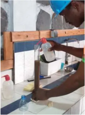
This test was conducted according to NF P 18-598 with class 0/5 sand. The sand equivalent test was done on three sand samples and the final result is the average of individual results. Two kinds of testing were performed, the visual sand equivalent (SE) (Fig.12, Fig.13 and Fig.14) and sand equivalent (SEP) from piston tests. The overall result is the average of visual sand equivalent and sand equivalent from piston which is SE = 86.56 >80% and thus the sand is very clean, almost total absence of fine clay, which does not risk causing a lack of plasticity in the concrete.
Figure 14 Measurement using the ruler
Table 13 Physico-chemical characteristics of the sand sample
Characteristics Sand 0/5
Fineness modulus 2.68
Absolute density (t/m3) 2.597
Apparent density Not specified
Based on the characteristics obtained in Tab. 13 above, we observe that the Sanaga sand is justified for our study. NF XP P 18-540 [34] specifies that for a value of the fineness modulus between 2.2 and 2.8, we have a good concrete sand that offers good workability and good resistance. On the other hand, according to Dreux and Gorisse (1969) [35], the good sand must have a fineness modulus around 2.5.
3.1.2.3 Density
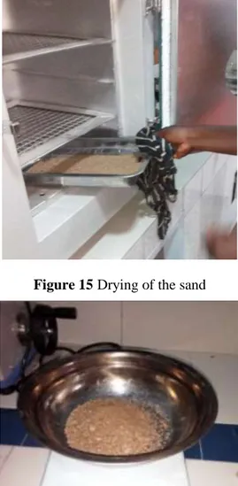
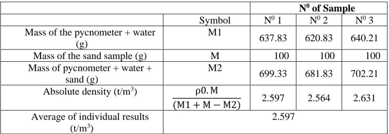
The absolute density of the sand was measured using a pycnometer. This test was conducted as follow: After drying a certain quantity of the sand in the oven for 24hours (Fig. 15) we weigh it (M) (Fig. 16), we filled the pycnometer with water and weigh it (M1) and then we poured the sand into this pycnometer and weigh it (M2) (Fig. 17).
The absolute density of the sand was calculated using the formula: ρr = ρ0.M / (M1 + M-M2)
Where: M1 (g) is the mass of the pycnometer + water M (g) is the mass of the sand sample
M2 (g) is the mass of the pycnometer + water + sand ρ0 is is the density of the water
Table 14 shows the average of individual results. The results (Table 14) obtained from three sand samples show that, from one measure to another, the density of the sand is not very different.
Figure 15Drying of the sand
Figure 16 Sand Weighing
Table 14 Absolute density of sand
N0 of Sample
Symbol N0 1 N0 2 N0 3 Mass of the pycnometer + water
(g)
M1
637.83 620.83 640.21
Mass of the sand sample (g) M 100 100 100
Mass of pycnometer + water + sand (g)
M2
699.33 681.83 702.21 Absolute density (t/m3) ρ0. M
(M1 + M − M2) 2.597 2.564 2.631 Average of individual results
(t/m3)
2.597 ρ0 is the density of the water (ρ0 = 1 t / m3)
3.1.3 Water
Water is an asymmetrical material consisting of an oxygen atom and two hydrogen atoms. It intervenes by its mechanical and physico-chemical properties at all stages of the life of the concrete, it ensures the hydration of the cement, confers its plasticity and allows its flow at fresh state [36]. The mixing water is rarely encountered in its pure state. It contains ions in solution and solid particles in suspension, the salts in low proportion dissolved in this water are involved in the rheology of cementitious matrix materials [36].
The water used in the manufacturing of concrete does not contain harmful elements and impurities in such quantities that they could adversely affect the setting, hardening and durability of the concrete. The amount of water is a function of the nature of the binder used, the prior humidity of the lightweight aggregates, and the use of the concrete. We assume that it meets all of the requirements of the standard (EN 1008) [37] for the regulation of mixing water for concrete and does not require testing.
Clean water for mixing lightweight concretes was obtained from public water system (Camwater).
3.1.4 Charcoal
The quality of lightweight aggregates is an important parameter for the manufacture of lightweight concretes. For this work, charcoal used in lightweight concrete is produced from eucalyptus plant (Fig. 18) in North West Region, Bamenda, Cameroon.
Figure 18 eucalyptus plant in Bamenda.
It is a type of wood that is more or less suitable for the manufacture of coal because of its density and the energy available during combustion. Charcoal was characterized by the following physical properties:
• Particle size analysis
The granular fraction of the coal used for our tests is 05/20. The particle size analysis is performed in accordance with the standard (not specified). Figure 22 shows the particle size distribution curve.
• Water absorption rate
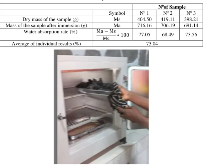
The water absorption rate test was performed on three (03) samples of charcoal. The results (Table 15) showed that the water absorption rate of the charcoal used is 73.04% (average of individual results). The water absorption test was conducted for quantifying the quantity of water which infiltrates in the pores of the pieces of charcoal, this water not being able to take part in the hydration reaction of the cement. After drying the pieces of charcoal in an oven (Fig.19) until constant mass we weigh it (Ms) (Fig. 20), we immerge the sample in water for 24 hours (Fig. 21) and weigh it (Ma) and measure the mass of the sample thus sponged. The water absorption rate of charcoal was calculated using the following equation:
Water absorption rate (%) = (Ma-Ms) / Ms Where: Ms is the dry mass of the sample (g)
Ma is the mass of the sample after immersion (g)
Table 15 Water absorption rate of charcoal
N0of Sample
Symbol N0 1 N0 2 N0 3 Dry mass of the sample (g) Ms 404.50 419.11 398.21 Mass of the sample after immersion (g) Ma 716.16 706.19 691.14
Water absorption rate (%) Ma − Ms
Ms ∗ 100 77.05 68.49 73.56
Average of individual results (%) 73.04
Figure 20Weighing charcoal after drying
Figure 21 Immersion of charcoal • Absolute density
The absolute density was measured using a pycnometer. The results (Table 16) obtained from three (03) charcoal samples show that, from one measure to another, the density of the charcoal is not very different. The results also showed that the absolute density of the charcoal used is 0.57t/m3 (average of individual results). The following steps were used for conducting
this test:
• Take a graduated cylinder and fill it to a certain water level (Fig. 23), read the volume V1 then, weigh this test tube and raise the mass M1.
• Take a certain amount of charcoal (this will depend on the size of the specimen). No need to weigh the mass of sample taken.
• Pour this charcoal into the test tube, read the new volume V2 then weigh this test tube and read the mass M2 (Fig. 24). The absolute density was calculated by applying this equation:
Absolute density (t/m3) = M2 − M1
(V2 − V1) Where: M1 is the mass of the specimen with water (g)
V1 is the volume of water contained in the test tube (ml) M2 is the mass of the specimen + water + charcoal (g) V2 is the volume of water + charcoal (ml)
Table 16 Absolute density of charcoal
N0 of Sample Symbol N0 1 N0 2 N0 3
Mass of the specimen with water (g) M1 326.03 311.16 321.13
Volume of water contained in the test tube (ml)
V1
200 200 200
Mass of the specimen + water + charcoal (g)
M2
363.8 349.11 363.16
Volume of water + charcoal (ml) V2 273.1 264.2 269.5
Absolute density (t/m3) M2 − M1
(V2 − V1) 0.516 0.591 0.604
Average of individual results (t/m3) 0.57
Figure 24Weighing the specimen containing water and charcoal
Figure 25 Particle size distribution curve of charcoal 5/20 used.
4. COMPOSITION OF LIGHTWEIGHT CONCRETES
Our experimental programme aims to contribute to the upgrading of charcoal aggregates by incorporating them into a cementitious matrix, for the development of a composite based on charcoal particles. This study examines the behaviour of a mortar in which sand has been substituted by charcoal aggregates. The objectives of this research are to develop a lightweight concrete made with Cameroonian charcoal as coarse lightweight aggregate and to evaluate its absorption, density and mechanical performance. The classical methods of formulation of concretes are difficult to apply to lightweight concretes impregnated with charcoal given the hydrophilic character of the aggregates used. Previous work on the subject uses methods of arbitrary formulations and disseminated in the form of trial and error [12]. Two methods were chosen for the composition of the materials studied in this work. The specimens were made with different formulations to better understand the influence of the formulation on the properties of the concrete sought.
0.89 1.16 4.39 11.93 46.17 93.33 100 5 6.3 8 10 12.5 16 20 0 10 20 30 40 50 60 70 80 90 100 Sieve diameter (mm) Pas si n g (% )
4.1 Dreux-Gorisse Formulation Method
4.1.1 Justification for the choice of the formulation method:
Since particle size and in particular absolute density are two parameters that vary considerably depending on the type of coal used, we have chosen to apply the Dreux-Gorisse formulation method. Particular importance is given to the particle size and absolute density of the aggregates of our lightweight concretes. The objective is to determine according to the criteria of workability, expected strength, the nature and quantities of materials required to manufacture a cubic metre of concrete (Water (W), Cement (C), Sand (S), Charcoal (Ch)) in Kg/m³).
Table 17 Mixture proportions for concrete samples (1m3).
Quantity in Kg Cement (C) Sand(S) Charcoal (Ch) Water (W)
Sample A 267 986.34 211.40 186.86
Sample B 289.28 963.56 206.52 202.39
Sample C 314.28 939.61 201.38 219.88
Sample D 342.21 914.42 195.99 239.31
Depending on the type of work to be performed, the parameters necessary for concrete implementation and for the short and long term stability of the structure must be defined. The main parameters to be defined are the workability, the expected strength of the concrete, the nature of the cement and the type of aggregates. The different proportions of concrete samples used are shown in Tab. 17.
4.2 Progressive formulation method
This method is based on a choice of a cementitious matrix that assigns a desired lightweight concrete, it is called MO, that is, the percentage of the lightweight aggregate is zero (control). For our mixtures, the search for a compromise resistance-workability led us to choose five compositions of lightweight charcoal concretes (LWCC) to test them. In this method, the sand will be progressively replaced by charcoal aggregates with a density of g = 25%, then 50%, 75% and finally 100% by volume of natural units by the additional volume of artificial assemblies. The cement and water dosage will remain constant. The choice of this method is justified by the fact that it will allow us to highlight the influence of charcoal in concrete. The different compositions used are shown in Tab. 18 below.
Table 18 Compositions of the different mixtures. Constituents (Kg/m3) M0 M25 M50 M75 M100 Charcoal 0 337.5 675 1012.5 1350 Sand 1350 1012.5 675 337.5 0 Cement 450 450 450 450 450 Water 225 225 225 225 225 g (%) 0% 25% 50% 75% 100% W/C 0.5 0.5 0.5 0.5 0.5
4.3 Mixes Design and Specimens Preparation
Lightweight concretes are made like normal concretes but with lightweight aggregates. The mixture proportions and components for the Dreux-Gorisse formulation and progressive formulation method are shown in Tab. 17 and Tab. 18, respectively. The mixing sequence of the constituent materials was as follows: Charcoal was mixed with cement for two minutes to
homogenize the mixture and then extended for another two minutes after the sand has been incorporated (Figure 25). The mixing water is then added, and the mixing is continued for two minutes. The mixing was done correctly to obtain a homogeneous mixture with uniform properties [38].
Figure 25 Dry mixing of different constituents of concrete
A flow chart of the methodology adopted to perform the experimental programme is given in Figure 26.
Figure 26 Research framework
5. TESTING METHODS
The samples of lightweight concretes made with different formulations were subjected to the following tests:
Collection of raw materials used
Cement (CN CEM II/B-P 42.5R) Sand Water Charcoal Characterization of raw materials
Trial mixing-mixing of charcoal, cement, sand and water in different proportions/ Formulation or development of lightweight charcoal concretes
Performance properties of developed lightweight charcoal concretes
5.1 Apparent density test
The Apparent density test was conducted on specimens of size 4×4×16 cm3. After preparing the samples, they were removed from the mold the day and stored in drinking water to prevent any water exchange with the outside, the temperature was kept constant at 20 ° C ± 1 ° C. Then, the weight (M) (Figure 27) and the dimensions of the sample were recorded and the volume (V) of the sample was calculated. The apparent density of the samples was calculated as follows:
𝐷=𝑀/V (1)
Where: M is the mass and V the volume of the tested sample.
Figure 27 Measurement of the mass of the concrete
5.2 Water Absorption
The water absorption tests were conducted to measure the water absorption properties of the lightweight concrete specimens. The equipment included the bucket, clean water, a balance and a stop watch. The test consisted of determining the amount of water absorbed by the lightweight concrete specimens for 24 hours. The samples after demolding (Figure 28) were oven dried for 48 hours, they then be weighed (W1), then immersed in water for 24 hours (Figure 29) and
weighed again (W2). The percentage of water absorption (A) was computed for each sample
using Equation 1.
A (%) = 𝑊2−𝑊1
𝑊2 × 100 (2)
Where: W1 = weight of lightweight concrete before immersion, W2 = weight of lightweight concrete after immersion.
Figure 29 Immersion of concrete samples in water
5.3 Compressive Strength
The compression test was used to determine the compressive strength of the lightweight concretes, as well as describe the behavior of the lightweight concretes when subjected to compressive load. The equipment included the compression machine and metallic plates to surmount the compressive plates. The lightweight concrete specimens at 7, 14 and 28 days of maturity were mounted on to the compression machine (Fig. 30) and the compressive load was increased at 0.05mm/S until the lightweight concrete fractured. The compressive strengths of the lightweight concretes were calculated using Equation 2.
𝝈 = F/S (3)
Where: 𝝈 = compressive strength, F = maximum load applied before failure, S = cross sectional area of the specimen.
Figure 30 Compressive strength testing machine
5.4 Tensile Strength
As we all know, concrete is strong in compression and weak in tension. In other words, the tensile strength of the concrete is very low, but it is important to know its value. Compared to the compressive behavior of concrete, the tensile behavior has received a little attention in the past, partly because it is a common practice to ignore tensile strength in reinforced concrete design [20, 36]. Interest in tensile properties has grown substantially in recent years partially due to introduction of fracture mechanics into the field of concrete structures [20, 36].
We had deduced the value of the tensile strength by using Equation 3.
Ftj = 0.6 + 0.06fcj (4)
5.5 Three-Point Bending Test
The three-point bending tests were conducted to determine the flexural strength of concrete specimens at 7 and 28 days. The tests were conducted on 40×40×160 mm3 samples where the support span was 100 mm. The load was applied at the middle of the specimens (Figure 31) with a span length of 100mm. The breaking stress (б) was calculated using the following equation:
б = 3/2 (FL / b3) (5)
Where, F is the breaking force, L is the span (100mm), b being the edge of square section (b = 40 mm).
Thus, б = 2.34375xF
Figure 31 Geometry of the cross-section of the specimen for three-point bending test
6. RESULTS AND DISCUSSION
6.1 Workability of the Concrete Lightweight and its Apparent Density
Figure 32 presents a comparison between the workability of the concrete and its apparent density using the Dreux-Gorisse formulation method. It can be seen that, when the workability of the concrete increases, its apparent density decreases. So the more the concrete is workable, the less dense it is. The average apparent density is approximately 1422.445 Kg/m3. This is in line with the definitions of lightweight concrete given by the American Concrete Institute, the RILEM, the Eurocode 2, the German standard, DIN 1042 (1972). The International Union of Laboratories and Experts in Construction Materials, Systems and Structures (RILEM) define lightweight concretes as concretes with a dry density of less than 1800 Kg/m3. The American Concrete Institute (ACI) limits the bulk density of lightweight concrete to 1800 Kg/m3 after air
drying for 28 days. The German standard, DIN 1042 (1972) limits the apparent density of a lightweight concrete to 2000 kg/m³. The Eurocode 2 limits the bulk density of lightweight concrete to 2200 Kg/m3 [11]. 1513.04 1454.37 1396.97 1325.4 1200 1250 1300 1350 1400 1450 1500 1550 A (1cm) B (2,9cm) C (5,2cm) D (7,5cm) App ar en t densi ty (K g /m 3 )
6.2 Effect or Influence of Charcoal on the Apparent Density of Concrete Specimens
The effect or influence of charcoal on the apparent density of concrete specimens using the progressive formulation method is shown in Fig 33. Specimen with charcoal exhibited lower apparent density than the control specimen. The apparent density of the control specimen is 1655 kg/m3. The apparent density of concretes decrease as the amount of charcoal increases in the mix. Charcoal is less dense than sand, so it is obvious that the substitution of sand by charcoal would lower the apparent density of concrete specimens. When the sands were substituted with charcoal aggregate contents at 25%, 50%, 75% and 100%, the apparent density values of concrete specimens were increased by 13.71%, 33%, 47.18% and 65.72%, respectively when compared with the control mix.
Figure 33 Apparent density of concrete as a function of charcoal content
6.3 Water Absorption of the Lightweight Concrete and its Density
Figure 34 shows the variation of the rate of water absorption of the lightweight concrete as a function of its density using Dreux-Gorisse formulation method. It can be seen that when the lightweight concrete density decreases, its water absorption rate decreases. The average rate of water absorption is approximately 30%. So the denser the lightweight concrete, the more it will absorb water.
Figure 34 Variation of the rate of water absorption of the concrete as a function of its density
1655 1428.06 1108.21 874.17 567.22 0 200 400 600 800 1000 1200 1400 1600 1800 0% 25% 50% 75% 100% App ar en t densi ty ( K g/m 3) Percentage of charcoal 34.1 32.5 27.2 25.9 A (1,51) B (1,45) C (1,39) D (1,32) 0 5 10 15 20 25 30 35 40
Name and density of the specimen
Wate r ab sor p tion r ate (% )
6.4 Effect or influence of charcoal on water absorption of concrete specimens
The results of the water absorption usingthe progressive formulation method are shown in Fig. 35. The coefficient of water absorption increases as the percentage of charcoal increases in the mix. So the more the concrete is rich in charcoal, the more it absorbs water. This can be explained by the fact that charcoal is a porous material. Sample of 0% charcoal replacement (control) had a lower water absorption compared to samples of 25%, 50%, 75%, and 100% charcoal replacement. When the sands were substituted with charcoal aggregate contents at 25%, 50%, 75% and 100%, the water absorption values of concrete specimens were increased by 74.60%, 87.90%, 90% and 91.65%, respectively when compared with the control mix.
Figure 35 Water absorption rate of concrete as a function of charcoal content.
6.5. Compressive Strength with Respect to The Density and Curing Time
Figure 36 Compressive strength of concrete as a function of time and density.
7.19 28.31 59.42 71.87 86.17 0% 25% 50% 75% 100% 0 10 20 30 40 50 60 70 80 90 100 Percentage of charcoal (%) Wate r ab sor p tion r ate (% ) 0 1 2 3 4 5 A (1,51) B (1,45) C (1,39) D (1,32) 2.903 2.783 2.561 2.461 3.828 3.657 3.36 3.254 4.693 4.494 4.125 4.002 Co m p re ssi ve s tre n gth (M P a)
Name and density of the specimen
A (1,51) B (1,45) C (1,39) D (1,32) C S at 7days 2.903 2.783 2.561 2.461 C S at 14 days 3.828 3.657 3.36 3.254 C S at 28 days 4.693 4.494 4.125 4.002
Compressive strength (C S)
C S at 7days C S at 14 days C S at 28 daysThe results of the compressive strength tests are shown in Fig. 36. The diagram shows the compressive strength with respect to the density and curing time using the Dreux-Gorisse formulation method. The American Concrete Institute (ACI) limits the bulk density of lightweight concrete to 1800 Kg /m3 after air drying for 28 days. It is observed from Figure 36, that all the mixtures are within the range for structural lightweight concrete. The density ranging from 1.32 t/m3 to 1.51 t/m3 or from 1320 Kg/m3 to 1510 Kg/m3. The compressive strength decreased with the reduction of the density of lightweight concrete. The compressive strength also increased as the curing time increased.
6.6. Effect or Influence of Charcoal on The Compressive Strength of Concrete Specimens
The variations of compressive strength of the control specimens and other specimens containing charcoal using the progressive formulation method are shown in Fig. 37. Samples of 0% charcoal replacement (control) had a greater compressive strength at each age compared to samples of 25%, 50%, 75%, and 100% charcoal replacement. The optimum compressive strength was obtained at 25% of charcoal replacement. The minimum compressive strength required for masonry units or bricks as stipulated by the South African standard (SANS 1215) [39] is 3.0 MPa and from 25 to 50% charcoal replacement give compressive strength between 3.92 and 5.08 MPa at 28 days of maturity, thus adequate for masonry applications. On the other hand, according to the French standards NF DTU 20-1 (1999) [40], NF P 14-304 (1983) [41], NF EN 771-3 (2011) [42] and NF EN 771-3 / CN (2012) [43], the compressive strength greater than the value of 2.5 MPa is required for the manufacture of lightweight aggregates concrete hollow blocks to be used to build non-load-bearing walls and partitions of buildings. Also, Spence and Cook [44] suggested an average brick strength ranging from 3.0 to 3.5 MPa for load bearing requirements of normal two-story buildings. The presence of charcoal poses problems of resistance, resulting in a decrease of the mechanical strength of the concrete. This is consistent with the literature on lightweight concrete, which notes that lightweight concretes are less resistant than conventional concretes. The decrease of the mechanical strength of concrete is probably due to the fact that charcoal, because of its low density and fragility, always tends to crumble, even under low stress. Thus, the strength of the concrete is relatively low. The low mechanical strength of lightweight charcoal concrete is also due to the high water absorption of charcoal aggregates (73.04%) and weak or poor bond between charcoal aggregate and binder.
Figure 37 Compressive strength of concrete as a function of time and charcoal content.
0 10 20 30 0% 25% 50% 75% 100% 11.23 3.11 2.29 1.88 1.14 21.17 5.08 3.92 2.87 2.48 Co m p re ssi ve s tre n gth (M P a) Percentage of charcoal (%) 0% 25% 50% 75% 100% C S at 7days 11.23 3.11 2.29 1.88 1.14 C S at 28 days 21.17 5.08 3.92 2.87 2.48
Compressive strength (C S)
C S at 7days C S at 28 daysThe evolutions of the resistances as a function of time show that at the beginning, the resistances decrease for all samples. Whereas the following periods, the resistances increase significantly. This is due to the kinetics of the cement hydration reaction. When the sands were substituted with charcoal aggregate contents at 25%, 50%, 75% and 100%, the compressive strength (CS) values of concrete specimens were reduced by 72.30%, 79.60%, 83.25% and 89.84%, respectively at curing age of 7 days and were reduced by 76%, 81.50%, 86.44% and 88.28%, respectively at curing age of 28 days when compared with the control mix.
Figure 38 Tensile strength of concrete as a function of time and density.
6.7 Tensile Strength with respect to the Density and Curing Time
The variations of tensile strength with respect to the density and curing time using the Dreux-Gorisse formulation method are shown in Fig. 38. The tensile strength decreased with the reduction of the density of lightweight concrete. The tensile strength also increased as the curing time increased.
6.8 Effect or Influence of Charcoal on the Tensile Strength of Concrete Specimens
The variations of tensile strength of the control specimens and other specimens containing charcoal using the progressive formulation method are shown in Fig.39. Samples of 0% charcoal replacement (control) had a greater tensile strength at each age compared to samples of 25%, 50%, 75%, and 100% charcoal replacement. The optimum tensile strength was obtained at 25% of charcoal replacement. The tensile strength evolves in a manner similar to that of compressive strength. The tensile strength is about 5 times lower than the compressive strength. When the sands were substituted with charcoal aggregate contents at 25%, 50%, 75% and 100%, the tensile strength (TS) values of concrete specimens were reduced by 37.80%, 42.51%, 44%, respectively at curing age of 7 days and were reduced by 48%; 51.87%, 58.82% and 60%, respectively at curing age of 28 days when compared with the control mix.
0.65 0.7 0.75 0.8 0.85 0.9 A (1,51) B (1,45) C (1,39) D (1,32) 0.774 0.767 0.754 0.748 0.83 0.82 0.801 0.795 0.881 0.87 0.847 0.84 Ten si le str e n gth (M Pa)
Name and density of the specimen
A (1,51) B (1,45) C (1,39) D (1,32) T S at 7days 0.774 0.767 0.754 0.748 T S at 14 days 0.83 0.82 0.801 0.795 T S at 28 days 0.881 0.87 0.847 0.84
Tensile strength (T S)
T S at 7days T S at 14 days T S at 28 daysFigure 39 Tensile strength of concrete as a function of time and charcoal content.
Figure 40 Flexural strength of concrete as a function of time and apparent density
6.9 Flexural Strength of Concrete Specimens and its Apparent Density
The results obtained for the flexural strength (F S) tests at curing ages of 7 and 28 days for eight specimens of concrete using the Dreux-Gorisse formulation method are illustrated in figure 40. It can be seen that as the apparent density of concrete decreases, the flexural strength also decreases. But this resistance increases with curing age.
6.10 Effect or Influence of Charcoal on the Flexural Strength of Concrete Specimens
Figure 41 shows the influence of charcoal on the bending or flexural strength (FS) of concrete specimens at curing ages of 7 and 28 days using the progressive formulation method. It can be seen that as the amount of charcoal increases in the concrete, its resistance to bending decreases.
0 0.5 1 1.5 2 0% 25% 50% 75% 100% 1.27 0.79 0.73 0.71 0.66 1.87 0.9 0.83 0.77 0.75 Te n si le s tre n gth (M P a) Percentage of charcoal (%) 0% 25% 50% 75% 100% T S at 7days 1.27 0.79 0.73 0.71 0.66 T S at 28 days 1.87 0.9 0.83 0.77 0.75 Tensile strength (T S) T S at 7days T S at 28 days 0 0.5 1 A (1,51) B (1,45) C (1,39) D (1,32) 0.58 0.548 0.486 0.465 0.939 0.854 0.817 0.756 F lexural str en gth (M P a)
Name and density of the specimen
A (1,51) B (1,45) C (1,39) D (1,32)
F S at 7days 0.58 0.548 0.486 0.465
F S at 28 days 0.939 0.854 0.817 0.756
Flexural strength (FS)
The control specimens have a flexural strength of 3.51 MPa and 5.13 MPa at 7 and 28 days of maturity, respectively. The optimum flexural strength was obtained at 25% of charcoal replacement. The flexural strengths of concretes increase with the increase in curing age in all the specimens. When the sands were substituted with charcoal aggregate contents at 25%, 50%, 75% and 100%, the bending or flexural strength (FS) values of concrete specimens were reduced by 59.25%, 78.34%, 86% and 88%, respectively at curing age of 7 days and were reduced by 56.53%, 67%, 88% and 91%, respectively at curing age of 28 days when compared with the control mix.
Figure 41 Resistance to bending of concrete as a function of time and charcoal content
7. CONCLUSIONS
This paper presents the lightweight concrete made with Cameroonian Charcoal as coarse lightweight aggregate and reports the absorption, density and mechanical performance of this kind of concrete.
Although lightweight concretes have been known around the world for over a quarter of a century, they are not employed yet in Cameroon. The possibility of substituting the conventional aggregates in the conventional concretes was explored. Based on the results obtained, the following conclusions were drawn:
• The water absorption of the charcoal used is 73.04%. • The absolute density of the charcoal used is 0.57 t/m3.
• The particle size distribution curve of the sand used showed that we have continuously graded sand with a fineness modulus of 2.68.
• The absolute density of sand used is 2.6 t/m3.
• When the charcoal content increases in the concrete, its mechanical resistance decreases.
• The tensile strength is about 5 times lower than the compressive strength.
• The lightweight concretes developed are applicable for masonry bricks production.
0 1 2 3 4 5 6 0% 25% 50% 75% 100% 3.51 1.43 0.76 0.49 0.42 5.13 2.23 1.54 0.61 0.46 F lexural str en gth (M P a) Percentage of charcoal (%) 0% 25% 50% 75% 100% F S at 7days 3.51 1.43 0.76 0.49 0.42 F S at 28 days 5.13 2.23 1.54 0.61 0.46
Flexural strength (FS)
F S at 7days F S at 28 days• When the charcoal content increases in the concrete, its water absorption rate also increases.
• The compressive, tensile and flexural strengths of concretes increase with the increase in curing time in all the mixes and the evolution from one formulation to another is rather similar.
• The apparent density of the concrete decreases with the increase in charcoal content • The flexural strength and tensile strengths evolve in a manner similar to that of
compressive strength.
REFERENCES
[1] Tchamba, J.C, Bikoko, T.G.L.J. Failure and Collapse of Building Structures in the Cities of Yaoundé and Douala, Cameroon from 2010 to 2014. Modern. Appl. Sci. 10(1) (2016) 23-33. [2] Neville, A. M, Brooks, J. J. Concrete Technology (2nd ed.). Longman Group, UK publishers
Ltd, 2010.
[3] Ezema, I.C, Olatunji, O. Building Collapse in Lagos State, Nigeria: Towards Quality Control in Materials, Batching and Placement of Concrete. Covenant. J. Res. Built. Environ. (CJRBE), 6 (1) (2018) 25-39.
[4] Benkhalfa, B. contribution à l’étude des bétons légers d’argile expanse pour des éléments armés préfabriqués. Thèse de magistère, Université d’Annaba, 1988.
[5] Mo, K.H, Ling, T.C, Alengaram, U.J, Yap, S.P, Yuen, C.W. Overview of supplementary cementitious materials usage in lightweight aggregate concrete. Constr. Build. Mater. 139 (2017) 403–418.
[6] Chen, H. J, Yang, M. D, Tang, C. W, Wang, S. Y. Producing synthetic lightweight aggregates from reservoir sediments. Constr. Build. Mater. 28 (2012) 387-394.
[7] Neville, A. Propriétés des bétons. Eyrolles. Paris, 2000.
[8] Fiorio, B, Beaucour, A.L, Ortola, S. Optimization of the Mechanical Behavior of Lightweight Aggregate Concrete by the use of High Performances Cementitious Matrixes, Symposium Fib (ceb – fip) / AFGC on Concrete Structures: the Challenge of Creativity, Avignon, France, April, 2004, pp. 26-28.
[9] Ke, Y, Beaucour, A. L, Ortola, S, Dumontet, H, Cabrillac, R. Comportement mécanique des bétons de granulats légers ; étude expérimentale et modélisation, In: XXIVéme Rencontres du Génie Civil et Urbain, Construire: les nouveaux défis, 2006a.
[10] Hannawi, K. Conception, Caractérisation physico-mécanique et durabilité de nouveaux matériaux de construction à caractère environnemental, INSA Rennes, France, 2011.
[11] The European Union per Regulation 305/2011; Directive 98/34/EC, D. 2004/18/EC Eurocode 2: Design of Concrete Structures. Part 1-1: General Rules and Rules for Buildings. Section 11: Lightweight Aggregated Concrete Structures; European Union: Brussels, Belgium, 2010. [12] Constant, M. Confection de bétons légers, la fabrication d’éléments architecturaux, projet
d'application présenté à L'école de technologie supérieure, Ecole de technologie supérieure, Université du Québec, Édition. Montréal, 14 Avril 2000.
[13] Shink, M. Compatibilité élastique, comportement mécanique et optimisation des bétons de granulats légers, Université Laval, Québec, Canada, Avril 2003.
[14] Ouided, H. Formulation et Caractérisation des Bétons Légers. Thèse de magistère. Université Mohamed Khider – biskra. 2010.
[15] Laoud, B. Caractérisation mécanique et physique d’un béton léger à base de sable calcaire et des granulats de liège. Int. J. Innovation. Appl. Stu. 3(3) (2013) 739-748.
[16] Aziz, M.A, Murphy, C.K, Ramaswamy, S.D. Lightweight concrete using cork granules. Int. J. Cem. Compos. Lightweight. Concr. 1(1) (1979) 29-33.
[17] Rahman, M.A. Effect of rice husk ash on the properties of bricks made from fired lateritic soil-clay mix. Mater. Struct. 21 (3), (1988) 222–227.
[18] Ledhem,A. Dheily, R.M. Benmalek, M.L. Queneudec, M. Properties of wood-based composites formulated with aggregate industry waste. Constr. Build. Mater. 14 (6-7) (2000) 341-350. [19] Tamba, S. Voumbo, L.M. Wereme, A. Gaye, S. Sissoko, G. Durabilité des bétons légers à base
de copeaux de bois. J. Sci. 7 (2007) 67–72.
[20] Kitouni, S. Houari, H. Lightweight concrete with Algerian limestone dust. Part I: Study on 30% replacement to normal aggregate at early age. Cerâmica 59 (2013) 600-608.
[21] Habibur Rahman Sobuz, Noor Md. Sadiqul Hasan, Nafisa Tamanna, Md. Saiful Islam. Structural Lightweight Concrete Production by Using Oil Palm Shell. J. Mater. Volume 2014, Article ID 870247, 6 pages http://dx.doi.org/10.1155/2014/870247.
[22] Afonso Miguel Solak, Antonio José Tenza-Abril, José Miguel Saval and Victoria Eugenia García-Vera. Effects of multiple supplementary cementitious materials on workability and segregation resistance of lightweight aggregate concrete, Sustainability 2018, 10, 4304, doi:10.3390/su10114304.
[23] Muralitharan, R.S, Ramasamy, V. Development of lightweight concrete for structural applications. J. Struct. Eng. 44(4) (2017) 1-5.
[24] Manu S. Nadesan, P. Dinakar. Mix design and properties of fly ash waste lightweight aggregates in structural lightweight concrete. Case. Stu. Constr. Mater. 7 (2017) 336–347.
[25] Maria Kaszynska, Adam Zielinski. Effect of lightweight aggregate on minimizing autogenous shrinkage in Self-Consolidating Concrete, Procedia Eng. 108(2015) 608 – 615.
[26] Sang-Yeop Chung, Mohamed Abd Elrahman, Dietmar Stephan. Effects of expanded polystyrene (EPS) sizes and arrangements on the properties of lightweight concrete, Mat. Struct. (2018) 51:57.
[27] Hongzhi Cui, T.Y. Lo, Feng Xing. The effect of slag on durability of lightweight concrete. In: Proceedings of the 2nd International Symposium on Service Life Design for Infrastructure, 4-6 October 2010, Delft, The Netherlands
[28] Payam Shafigh, U. Johnson Alengaram, Hilmi Bin Mahmud, Mohd Zamin Jumaat. Engineering properties of oil palm shell lightweight concrete containing fly ash. Mater. Des. 49 (2013) 613– 621.
[29] Payam Shafigh, Hilmi Bin Mahmud, Mohd Zamin Jumaat. Oil palm shell lightweight concrete as a ductile material. Mater. Des. 36 (2012) 650–654.
[30] Jonathan Page, Mohammed Sonebi, Sofiane Amziane (2016) Étude expérimentale des propriétés d’un béton de chanvre incorporant un adjuvant viscosant, Revue des composites et des matériaux avancés – n° 3-4/2016, 349-366.
[31] Divya Patel, Uresh Kachhadia, Mehul Shah, Rahul Shah. Experimental Study on Lightweight Concrete with Styrofoam as a Replacement for Coarse Aggregate, ICRISET2017. In: Proceedings of the International Conference on Research and Innovations in Science, Engineering & Technology, Volume 1, 2017, pp. 103-108.
[32] Catalina Mihaela Helepciuc (Gradinaru), Marinela Barbuta, Adrian Alexandru Serbanoiu. Characterization of a lightweight concrete with sunflower aggregates, Procedia Manufacturing, 22(2018), 154-159.
[33] Norme française NF P 18-101: Analyse granulometrique-Web GRR NF P 08 501. [34] NF XP P 18-540: Granulats-Definition, conformité, specification. Octobre 1997.
[35] Dreux, G.; Gorisse, F.; Contribution à l’étude de la finesse des sables sur diverses qualités des bétons, annales, I. T. B. T. P. n° 261. 41 p.1969.
[36] Bikoko, T.G.L.J, Katte, V.Y, Bawe, G.N, Fokou Dongmene, M, Okonta, F.N, Tchamba, J.C. Characterisation of lightweight concrete impregnated with cement and charcoal. In: S. Amziane and M. Sonebi (Eds). Proceedings of the 3rd International Conference on Bio-based Building Materials, 26-28 June, Belfast, 2019, UK, pp. 229-237.
[37] EN 1008: Norme européenne de l’eau de gâchage pour bétons, specifications d'échantillonnage, d'essais et d'évaluation de l'aptitude à l'emploi (juillet 2003).
[38] Tchamba, J. C. Contribution à l’étude expérimentale du comportement des matériaux cimentaires au jeune âge: pression; rhéologie et perméabilité. (Unpublished doctoral thesis), Université de Bretagne Sud, Lorient, France, 2008.
[39] South African National Standards, SANS 1215 - Concrete Masonry Units, Standards South Africa, Pretoria, 2008.
[40] NF DTU 20-1 (1999), Building works-Masonry structures for small elements-Walls and walls-Part 2: Design rules and minimum construction requirements-Addendum 2 to the P10-202-2 standard of April 1994. AFNOR, Paris.
[41] NF P 14-304 (1983): Agglomerates - Concrete blocks of light aggregates for walls and partitions. AFNOR, Paris.
[42] NF EN 771-3 (2011). Specification for masonry units - Part 3: Concrete masonry aggregates (common and light aggregates). AFNOR, Paris.
[43] NF EN 771-3 / CN (2012). Specification for masonry units - Part 3: Concrete masonry aggregates elements (common and light aggregates) - National supplement to NF EN 771-3: 2011. AFNOR, Paris.
[44] Spence, R. J. S, Cook, D. J. Building Materials in Developing Countries, John Wiley and Sons, Chichester, England., 1983.

![Figure 7 Radiograpy images of EPS aggregate concrete specimens [26].](https://thumb-eu.123doks.com/thumbv2/123doknet/14645795.550232/11.892.137.756.120.385/figure-radiograpy-images-eps-aggregate-concrete-specimens.webp)
![Figure 8 Apparent density of hemp concretes [30].](https://thumb-eu.123doks.com/thumbv2/123doknet/14645795.550232/12.892.182.716.126.464/figure-apparent-density-hemp-concretes.webp)
![Figure 10 Thermal conductivity of hemp concretes as a function of apparent density [30]](https://thumb-eu.123doks.com/thumbv2/123doknet/14645795.550232/13.892.196.698.126.432/figure-thermal-conductivity-hemp-concretes-function-apparent-density.webp)