HAL Id: hal-01930274
https://hal.archives-ouvertes.fr/hal-01930274
Submitted on 21 Nov 2018
HAL is a multi-disciplinary open access
archive for the deposit and dissemination of
sci-entific research documents, whether they are
pub-lished or not. The documents may come from
teaching and research institutions in France or
abroad, or from public or private research centers.
L’archive ouverte pluridisciplinaire HAL, est
destinée au dépôt et à la diffusion de documents
scientifiques de niveau recherche, publiés ou non,
émanant des établissements d’enseignement et de
recherche français ou étrangers, des laboratoires
publics ou privés.
Resection-induced brain-shift compensation using
vessel-based methods
Fanny Morin, Hadrien Courtecuisse, Ingerid Reinertsen, Florian Le Lann,
Olivier Palombi, Yohan Payan, Matthieu Chabanas
To cite this version:
Fanny Morin, Hadrien Courtecuisse, Ingerid Reinertsen, Florian Le Lann, Olivier Palombi, et al..
Resection-induced brain-shift compensation using vessel-based methods. SPIE Medical Imaging 2018,
Feb 2018, Houston, TX, United States. pp.105760Q-1 - 105760Q-6, �10.1117/12.2293640�.
�hal-01930274�
Resection-induced brain-shift compensation using
vessel-based methods
Fanny Morin
a,b, Hadrien Courtecuisse
b,c, Ingerid Reinertsen
d,e, Florian Le Lann
f, Olivier
Palombi
f, Yohan Payan
aand Matthieu Chabanas
aa
University of Grenoble Alpes, CNRS, Grenoble INP, TIMC-IMAG, F38000 Grenoble, France
bUniversity of Strasbourg, CNRS, AVR-ICube, F67000 Strasbourg, France
c
MIMESIS, INRIA, Nancy, France
d
SINTEF, Departement of Medical Technology, Trondheim, Norway
e
Norwegian National Advisory Unit of Ultrasound and Image-Guided Therapy, St. Olav
University Hospital, Trondheim, Norway
f
Department of Neurosurgery, Grenoble Alpes University Hospital, F38000 Grenoble, France
ABSTRACT
Most brain-shift compensation methods address the problem of updating preoperative images to reflect brain deformations following the craniotomy and dura opening. However, fewer enable to take into account the resection-induced deformations occuring all along the tumor removal procedure. This paper evaluates the use of two existing methods to tackle that problem. Both techniques rely on blood vessels segmented then skeletonized from preoperative MR Angiography and navigated Doppler Ultrasound images acquired during resection. While the first one proposes to register the vascular trees using a rigid modified ICP algorithm, the second method relies on a non-rigid constrained-based biomechanical approach. Quantitative results are provided, based on distances between paired landmarks set on blood vessels then anatomical structures delineated on medical images. A qualitative evaluation of the compensation is also presented using initial and updated images. An analysis on three cases of surface tumor shows both methods, especially the biomechanical one, can compensate up to 63% of the brain-shift, with an error in the range of 2 mm. However, these results are not reproduced on a more complex case of deep tumor. While more patients must be included, these preliminary results show that vessel-based methods are well suited to compensate for resection-induced brain-shift, but better outcomes in complex cases still require to improve the methods to take the resection into account.
Keywords: Resection-induced brain-shift, Vessel-based registration method, Intraoperative ultrasound
1. INTRODUCTION
For brain tumor procedures, planning and image-guided navigation are based on preoperative Magnetic Reso-nance (pMR) images. However, these images do not account for the intraoperative deformation of soft tissues, called brain-shift, affecting the accuracy of the procedure. While causes of this shift are numerous, for example gravity or cerebrospinal fluid loss,1 tumor resection is one of the most important. A solution is to reimage the brain during surgery, to acquire data reflecting the current shape of the tissue. An image-to-patient registration can then map high-resolution pMR images to these intraoperative data, providing updated images to the surgeon. In the literature, craniotomy-induced brain-shift occuring before or just after dura opening is a widely studied topic.2–7 However, fewer works deal with the image-to-patient registration during the whole procedure, to take into account the deformation induced by tissue retraction and tumor resection itself. Some authors have simply used their craniotomy-induced compensation methods, while others have proposed to take account for the cavity formed by the resection. The following paragraphs, organized by the modality of intraoperative images, summarize a state of the art.
Different groups have proposed to register pMR with intraoperative Magnetic Resonance (iMR) images, acquired once or even several times during tumor resection. While of reduced quality with respect to pMR,
this imaging system provides dense volumetric information. Images can be mapped using fiducials8 or image-based registration methods.9–11 Other authors use a biomechanical model for the registration,12 sometimes with the removal of elements (or anniliation of their mechanical effects) localized inside the resection cavity.13, 14 Nonetheless, and regardless of their accuracy, these methods cannot be widely spread in clinical practice due to the cumbersomeness and cost of intraoperative MR devices. Another option is to digitize the brain cortical surface during resection, through the craniotomy, using stereovision image pairs or laser range systems. Their coupling with a mechanical model accounting for the retraction and/or resection yielded to significant results.11, 15 A recent retrospective study also compared outcomes from simulated surface data with actual iMR imaging.16 Finally, another intraoperative framework is Ultrasound (iUS) imaging. In addition to providing sub-surface data, this system is in widespread use, portable, cost-effective and do not require major changes in the surgical procedure. On one hand, image-based methods can be used to register pMR and iUS acquired during or after resection, using generated peudo-US images,17 LC metrics6 or patch-based correlation ratio,18 with promising or less conclusive results.19 On the other hand, iUS were used with a model-based method,20 with the neutralization of mechanical elements inside the resection cavity. While encouraging, a difficulty is to precisely define which elements have to be removed, especially when tissue debulking occur.
In this paper, we consider Power Doppler iUS to assess the value of blood vessels for brain-shift compen-sation during resection. Two methods initially developed for craniotomy-induced brain-shift compensation are evaluated, with no further treatments.
2.
METHODS
2.1
Vessel-based methods
This section provides a short description of the evaluated vessel-based methods. Both rely on the acquisition of pMR and pMR Angiography (pMRA) exams before surgery, then intraoperative navigated Doppler and/or B-mode iUS images. A 3D iUS volume is reconstructed out of the navigated 2D slices. Ultrasound acquisitions are performed directly in contact with the brain and, during resection, the cavity formed by the removed tissue is filled with saline.
Modified ICP method2 Blood vessels are segmented then skeletonized from the pMRA and Doppler iUS images. A modified Iterative Closest Point (ICP) algorithm is then used to register the vascular trees with the particularity to only consider the n% pairings having the smallest distances. The computed rigid transformation is finally applied to the iUS images.
Constraint-based biomechanical method3 Preoperatively, brain soft tissues and blood vessels are re-spectively extracted from pMR and pMRA. A tetrahedral Finite Element (FE) mesh, only accounting for the hemisphere affected by the tumor, is then mechanically coupled with the vascular tree skeleton. Intraopera-tively, Power Doppler and B-mode information are recorded simultaneously, respectively allowing to extract the blood vessels and probe footprint. A biomechanical simulation, relying on a linear constitutive law solved with a co-rotational approach, is used to compensate for brain-shift, accounting for boundary conditions (contacts with the dura mater, the falx cerebri and the tentorium cerebelli) and loads (applied to register blood vessels and maintain brain tissue under the US probe footprint) expressed as Lagrangian Multipliers constraints. After resolution, pMR images are updated with the FE model deformations.
2.2
Experiments
Four patients suffering from low grade tumor are included in this study. In the first three cases, the tumor was located in the brain periphery. For the fourth one, is was located deeper into the brain. All patients underwent surgery at Saint Olav Hospital, Trondheim, Norway, and data were collected by SINTEF Medical Technology. During the procedure, the navigation system Sonowand21 was used to acquire navigated B-mode and Doppler iUS images. These acquisitions’ characteristics are presented in Table 1. For each patient, an iUS acquisition was performed in the middle or near the end of the resection procedure.
Table 1. Description of the experimental data. t0refers to the dura opening time. The number of landmarks set on blood vessels and the anatomical structures delineated for the validation are specified for each patient, as well as the tumor location in depth.
Case Acquisition time Vessel landmarks Anatomical structure Tumor location
1 t0+ 107 min 5 Prefrontal sulcus Surface 2 t0 + 94 min 8 Sylvian fissure Surface 3 t0 + 97 min 5 Central sulcus Surface 4 t0+ 192 min 9 Sylvian fissure Deep
For the evaluation, five to nine paired landmarks were manually identified on vessels in the pMRA and Doppler iUS images. Note that there is a bias since vessels are also used to drive the registration, although not specifically these landmarks. In addition, anatomical structures such as sulci were delineated by a clinician in the pMR and B-mode iUS acquisitions. This evaluation process is similar to the one used to validate our vessel-based methods at the opening of the dura.3
3. RESULTS
Quantitative results on blood vessels landmarks and delineated anatomical structures are presented in Table 2. Table 2. Mean distances±sd between paired landmarks identified on blood vessels, then mean closest-point Euclidian distances±sd between the delineated anatomical structures. Distances are given before compensation, after compensation using the modified ICP,2 then after the constraint-based biomechanical method.3 Maximal distances are provided in parenthesis. All values are specified in mm. The percentage of associated points is shown in square brackets.
Case Before compensation Modified ICP method2 Constraint-based biomech. method3
Evaluation on vessels landmarks
1 3.54±0.93 (5.02) 2.07±0.74 (3.42) 1.76±0.69 (2.43)
2 7.11±1.24 (8.70) 2.46±1.98 (6.39) 2.35±0.99 (3.99)
3 6.54±1.40 (9.08) 2.45±0.82 (3.78) 1.89±0.26 (2.21)
4 9.05±2.08 (12.83) 6.74±1.87 (10.41) 6.49±2.45 (10.27)
Evaluation on anatomical structures
1 1.21±0.78 (4.88) [76%] 1.56±0.86 (4.19) [77%] 1.23±0.72 (4.14) [78%] 2 2.86±2.19 (10.49) [52%] 1.26±0.97 (6.06) [82%] 1.09±0.99 (7.42) [82%] 3 2.59±1.51 (8.04) [71%] 0.98±0.57 (3.01) [86%] 1.27±0.77 (3.76) [83%] 4 4.91±1.33 (7.79) [43%] 1.02±0.80 (6.13) [82%] 0.99±0.77 (5.70) [90%]
3.1
Surface tumor, cases 1-3
All distances (mean, max and sd) between blood vessels landmarks are significantly reduced using both brain-shift compensation techniques, proving an accurate registration in the vessel areas. The constraint-based biomechan-ical method provides better registration results with an average compensation score of 63% against 56% for the rigid modified ICP. In addition, the registration of the anatomical surfaces is also globally improved (distances are lower and the number of associated points is increased).
The order of magnitude of the remaining shit is similar to the ones obtained just after dura opening.3, 5, 18 During resection, these results can therefore be considered very satisfying. This can be confirmed qualitatively, as shown in Figures 1 and 2.
3.2
Deep tumor, case 4
Case 4 is clearly more complex. With regard to the distance between vessels landmarks, the remaining error after both compensation methods is much higher, in mean, max as well as standard-deviation. While an improvement is shown, from 9 to 6.5 mm approximately, all these factors indicate a non-sufficient compensation of the brain-shift during resection.
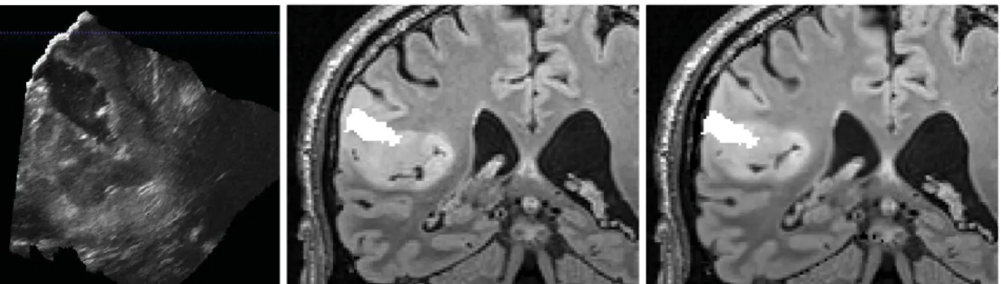
Figure 1. Brain-shift compensation for patient 1 using the constraint-based biomechanical method. Slices of the pMR (left), B-mode iUS images (middle) and updated pMR (right) are shown. A pointer first shows the borders of the exposed cortical surface (top row) then a deep sulcus bifurcation point (bottom row). The black area in the iUS image is the current resection cavity.
Figure 2. Intraoperative iUS image during tumor resection of case 3 (left). The resected cavity is segmented, then overlaid on the preoperative pMR (middle) and the updated pMR images (right). Nb: for rendering clarity, the iUS image scale is different.
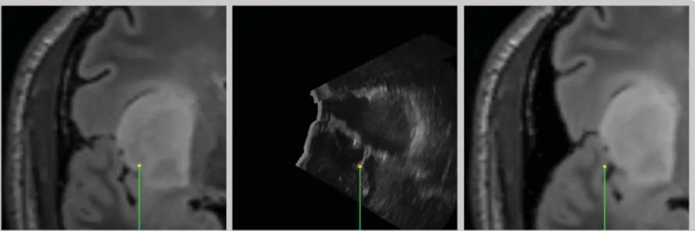
Figure 3. Brains-shift compensation for case 4, resection of a deep tumor. An anatomical landmark of the Sylvian sulcus is pointed on the pMR, iUS and updated pMR images. While the correction is adequate in depth, it is not satisfactory in the lateral direction. Qualitatively, the cavity (in this case a retraction then a resection area) cannot be well surperposed on the updated pMR images.
Surprisingly, the distances based on the Sylvian sulcus does not confirm this, as they are similar to previous cases. An explanation can be given by the non-discriminant geometry of the delineated sulcus near the tumor, alike a 3D “U shape”. As shown in Figure 3, the shift is in fact well corrected in depth, but an important sliding movement can still be observed in the lateral direction. In addition to deformations larger than in cases 1-3, the vessels are here located on one side of the tumor only which can explain the poor lateral accuracy.
4. CONCLUSION
This paper addresses the topic of resection-induced brain-shift compensation. We have shown the interest of accounting for the vascular tree to correct these deformation, using existing vessel-based methods without additional treatment.2, 3 While more cases must be obviously be considered, first results show a significant improvement of the pre-to-intraoperative registration in the case of surface tumors. In a more complex case, the model-based methods in their current state are not successful.
Two conclusions can be established. First, while deformation and topological changes occur locally within the tissues, surrounding vessels still provide a reliable mean to track the brain and tumor location. However, unless in simple cases, methods designed for craniotomy-induced brain-shift are too limited and must be improved to correctly match the deformation during retraction and resection.
Future works include the development of such a method, plus the combine use of Doppler and B-mode iUS images to drive the registration with both vessels and anatomical structures, like the sulci themselves.
Acknowledgment
This work was partly supported by the French National Research Agency (ANR) through the frameworks
In-vestissements d’Avenir Labex CAMI (ANR-11-LABX-0004) and Infrastructure d’Avenir en Biologie et Sant´e
(ANR-11-INBS-0006), and by a France-Norway partnership (PHC Aurora 2015/Research Council of Norway).
REFERENCES
1. I. J. Gerard, M. Kersten-Oertel, K. Petrecca, D. Sirhan, J. A. Hall, and D. L. Collins, “Brain shift in neuronavigation of brain tumors: A review,” Medical Image Analysis 35, pp. 403–420, 2017.
2. I. Reinertsen, F. Lindseth, C. Askeland, D. H. Iversen, and G. Unsgard, “Intra-operative correction of brain-shift,” Acta Neurochirurgica 156, pp. 1301–1310, 2014.
3. F. Morin, H. Courtecuisse, I. Reinertsen, F. Le Lann, O. Palombi, Y. Payan, and M. Chabanas, “Brain-shift compensation using intraoperative ultrasound and constraint-based biomechanical simulation,” Medical
4. R. R. Garlapati, A. Roy, G. R. Joldes, A. Wittek, A. Mostayed, B. Doyle, S. K. Warfield, R. Kikinis, N. Knuckey, S. Bunt, and K. Miller, “More accurate neuronavigation data provided by biomechanical modeling instead of rigid registration,” Journal of neurosurgery 120(6), pp. 1477–1483, 2014.
5. M. I. Miga, K. Sun, I. Chen, L. W. Clements, T. S. Pheiffer, A. L. Simpson, and R. C. Thompson, “Clinical evaluation of a model-updated image-guidance approach to brain shift compensation: experience in 16 cases,” International journal of computer assisted radiology and surgery 11(8), pp. 1467–1474, 2015. 6. B. Fuerst, W. Wein, M. Mller, and N. Navab, “Automatic ultrasoundMRI registration for neurosurgery
using the 2d and 3d LC2 Metric,” Medical Image Analysis (18), pp. 1312–1319, 2014.
7. H. Rivaz, S. J.-S. Chen, and D. L. Collins, “Automatic Deformable MR-Ultrasound Registration for Image-Guided Neurosurgery,” IEEE Transactions on Medical Imaging 34(2), pp. 366–380, 2015.
8. C. Nimsky, O. Ganslandt, P. Hastreiter, and R. Fahlbush, “Intraoperative Compensation for Brain Shift,”
Surgical Neurology 56(6), pp. 357–364, 2001.
9. A. Nabavi, P. M. Black, D. T. Gering, C.-F. Westin, V. Mehta, R. S. Pergolizzi, M. Ferrant, S. K. Warfield, N. Hata, R. B. Schartz, W. M. Wells, R. Kikinis, and F. A. Jolesz, “Serial Intraoperative Magnetic Resonance Imaging of Brain Shift,” Neurosurgery 48(4), pp. 787–798, 2001.
10. N. Archip, O. Clatz, S. Whalen, D. Kacher, A. Fedorov, A. Kot, N. Chrisochoides, F. A. Jolesz, A. J. Golby, P. M. Black, and S. K. Warfield, “Non-rigid alignment of pre-operative MRI, fMRI, and DT-MRI with intra-operative MRI for enhanced visualization and navigation in image-guided neurosurgery,” NeuroImage 35, pp. 609–624, 2007.
11. X. Fan, D. W. Roberts, J. D. Olson, S. Ji, T. J. Schaewe, D. A. Simon, and K. D. Paulsen, “Image Updating for Brain Shift Compensation During Resection,” Operative Neurosurgery , pp. 1–10, 2017.
12. O. Clatz, H. Delingette, I.-F. Talos, A. J. Golby, R. Kikinis, F. A. Jolesz, N. Ayache, and S. K. Warfield, “Robust Nonrigid Registration to Capture Brain Shift From Intraoperative MRI,” IEEE Transactions on
Medical Imaging 24(11), pp. 1417–1427, 2005.
13. M. Ferrant, A. Nabavi, B. Macq, P. M. Black, F. A. Jolesz, R. Kikinis, and S. K. Warfield, “Serial registration of intraoperative MR images of the brain,” Medical Image Analysis 6(4), pp. 337–359, 2002.
14. L. M. Vigneron, L. Noels, S. K. Warfield, J. G. Verly, and P. A. Robe, “Serial FEM/XFEM-Based Update of Preoperative Brain Images Using Intraoperative MRI,” International Journal of Biomedical Imaging 2012, p. 872783, 2012.
15. M. I. Miga, D. W. Roberts, F. E. Kennedy, L. A. Platenik, A. Hartov, K. E. Lunn, and K. D. Paulsen, “Modeling of Retraction and Resection for Intraoperative Updating of Images,” Neurosurgery 49(1), pp. 75– 85, 2001.
16. M. Luo, S. F. Frisken, J. A. Weis, L. W. Clements, P. Unadkat, R. C. Thompson, A. J. Golby, and M. I. Miga, “Retrospective study comparing model-based deformation correction to intraoperative magnetic resonance imaging for image-guided neurosurgery,” Journal of Medical Imaging 4, p. 1, Sept. 2017.
17. L. Mercier, D. Araujo, C. Haegelen, R. F. Del Maestro, K. Petrecca, and D. L. Collins, “Registering pre-and postresection 3-dimensional ultrasound for improved visualization of residual brain tumor,” Ultrasound in
medicine and biology 39(1), pp. 16–29, 2013.
18. H. Rivaz and D. L. Collins, “Deformable registration of preoperative MR, pre-resection ultrasound, and post-resection ultrasound images of neurosurgery,” International journal of computer assisted radiology and
surgery 10(7), pp. 1017–1028, 2015.
19. M. Riva, C. Hennersperger, F. Milletari, A. Katouzian, F. Pessina, B. Gutierrez-Becker, A. Castellano, N. Navab, and L. Bello, “3d intra-operative ultrasound and MR image guidance: pursuing an ultrasound-based management of brainshift to enhance neuronavigation,” International journal of computer assisted
radiology and surgery , pp. 1–15, 2017.
20. M. Bucki, O. Palombi, M. Bailet, and Y. Payan, “Doppler Ultrasound Driven Biomechanical Model of the Brain for Intraoperative Brain-Shift Compensation: A Proof of Concept in Clinical Conditions,” in Soft
Tissue Biomechanical Modeling for Computer Assisted Surgery, Y. Payan, ed., pp. 135–165, Springer, 2012.
21. A. Gronningstaeter, A. Kleven, S. Ommedal, T. E. Aarseth, T. Lie, F. Lindseth, T. Lango, and G. Unsgard, “SonoWand, an ultrasound-based neuronavigation system,” Neurosurgery 47(6), pp. 1373–1380, 2001.