HAL Id: hal-02603696
https://hal.archives-ouvertes.fr/hal-02603696
Submitted on 16 May 2020
HAL is a multi-disciplinary open access
archive for the deposit and dissemination of sci-entific research documents, whether they are pub-lished or not. The documents may come from teaching and research institutions in France or abroad, or from public or private research centers.
L’archive ouverte pluridisciplinaire HAL, est destinée au dépôt et à la diffusion de documents scientifiques de niveau recherche, publiés ou non, émanant des établissements d’enseignement et de recherche français ou étrangers, des laboratoires publics ou privés.
Modeling co-simulation : a first experiment
Renan Leroux-Beaudout, Ileana Ober, Marc Pantel, Jean-Michel Bruel
To cite this version:
Renan Leroux-Beaudout, Ileana Ober, Marc Pantel, Jean-Michel Bruel. Modeling co-simulation : a first experiment. 5th International Workshop on the Globalization of Modeling Languages (GEMOC 2017) co-located with ACM/IEEE 20th International Conference on Model Driven Engineering Lan-guages and Systems (MODELS 2017), Sep 2017, Austin, TX, United States. pp.292-297. �hal-02603696�
OATAO is an open access repository that collects the work of Toulouse
researchers and makes it freely available over the web where possible
Any correspondence concerning this service should be sent
to the repository administrator:
[email protected]
This is an author’s version published in:
https://oatao.univ-toulouse.fr/22252
To cite this version:
Leroux-Beaudout, Renan and Ober, Ileana and Pantel, Marc and
Bruel, Jean-Michel Modeling co-simulation : a first experiment.
(2017) In: 5th International Workshop on the Globalization of
Modeling Languages (GEMOC 2017) co-located with ACM/IEEE
20th International Conference on Model Driven Engineering
Languages and Systems (MODELS 2017), 17 September 2017
(Austin, TX, United States).
Modeling co-simulation: a first experiment
Renan Leroux1,2 Ileana Ober1 Marc Pantel1 Jean-Michel Bruel1
1IRIT / University of Toulouse
[firstName.lastName]@irit.fr
2Institute of Research and Technology (IRT) Saint Exupery, Seconded from Altran
Abstract—Model-Based Systems Engineering plays a key role in managing the complexity in the development of modern cyber-physical systems. Model simulation allows conducting early validation and verification activities. In the context of Extended Enterprises, systems are built out of components developed in different companies as black boxes to protect the company Intellectual Property. Simulation activities then rely on co-simulation that combines the black box simulation of each component to assess the quality of the whole system. Such activities are difficult to harness as the simulation results depend on black box co-simulation frameworks that coordi-nate the simulations of each component. Our work targets the modeling of these simulations including the co-simulation framework in order to: a) make explicit all the simulation choices and have a better understanding of the simulation results and b) benefit from model-driven engineering facil-ities including automatic code generation. This contribution describes an early experiment based on the classical bouncing ball game example.
1. Introduction
Nowadays the development of an important number of real-life applications is done by organizations structured as EE (Extended Enterprise). In an EE, a contracting authority and several subcontractors cooperate in complex work-flows for the development of complex systems such as cars, air-planes, power plants, etc. A key issue is the protection of the IP (Intellectual Property) of the various partners. SE (System Engineering) [1] is an interdisciplinary approach used to harness the development of such systems early in the V cycle, aiming at correct by construction processes. MDE (Model Driven Engineering) [2] relies on formal models to abstract the complexity of such systems using domain specific languages. On a wider scope, MBSE (Model-Based Systems Engineering) can be seen as the collection of related processes, methods, and tools used to support the discipline of systems engineering with an intensive use of models.
In the context of EE, MBSE allows the use of various kinds of models as core artifacts during the product devel-opment. The exchanges between the various collaborators are based on models, whose nature and content have to
be defined beforehand and properly included in a holistic systems engineering methodology while protecting the IP of all the partners. Thus, full models will never be available to all partners but only the minimal amount of data required to conduct an efficient development.
Simulation is often used to help the system architect assessing the adequacy of his/her architecture. In an EE, partners only develop parts of the whole system and must thus provide a simulator for each part. Then, all these simulation components are integrated in a co-simulation in order to assess the whole system. Such frameworks rely on co-simulation framework that integrate the components in a black box manner to protect the partners IP. The FMI (Functional Mockup Interface) [3] 2.0 co-simulation standard and the associated tools are currently the most ad-vanced technologies for building such co-simulators taking into account the constraints of EE including IP protection during the integration of FMU (Functional Mockup Unit) simulation components. The framework provides a so called master algorithm that coordinates the various simulation components.
We target the development of complex cyber physical systems for the transportation domain. We rely on het-erogeneous simulations (cross-domains, involving different kinds of models, possibly mixing continuous and discrete execution models, . . . ) to verify that the various functions in an architecture are activated according to the expected scenarios. Each function simulator is given as a black box FMU to protect the provider IP. A master algorithm is then used to coordinate the execution of these function simulators during each simulation step relying on the very restricted data provided to describe the FMU. Most FMI frameworks provide a generic black box master algorithm that drives the simulation according to the architecture of the simulator and the properties of each component. But, the various frameworks make different undocumented choices that may lead to quite different simulation results. Indeed, the precise management of time and function simulators execution order plays a key role in the quality of the simulation of such systems. For example, in hybrid systems that involve dis-crete behaviors, if the state of an FMU changes between two simulation steps, it may be important to compute the precise date when the state changed and to restart the simulation at
this exact date (rollback).
Our work targets a system modeling and simulation methodology that takes into account concerns related to the EE, in particular the IP protection, and ensures precise and deterministic simulation results. This paper contributes ques-tions and some model based preliminary answers derived from a simple bouncing ball example implemented with the JavaFMI framework[4]:
• When are rollback required in simulation?
• Should the rollback be managed inside or outside the FMU?
• In which order should the function simulators be executed in case of algebraic loops (data dependence loops)?
• How can a simulation model ease the management of these issues?
• Can the master algorithm be generated easily from such simulation model?
The remaining of this paper is as follows. In section 2, we provide a short description of the use case. In section 3, we explore some existing practices and state of the art for building simulators. In section 4, we explain the need for distinguishing the system model and the simulation model to provide a clear separation of concern. We conclude in section 5 and provide future work directions.
2. A simple example: the bouncing ball
We rely on a very simple example to illustrate the need for a simulation model and its relation with the system model. This example should comprise several parts that could be provided by several stakeholders and requires the use of co-simulation frameworks. We consider a simple bouncing ball where one part is the free fall of the ball and the other part is the collision with the ground. When the ball is left free above the surface, it accelerates due to gravitational forces. When the ball eventually comes in contact with the surface, it bounces off the surface, at a velocity that is a fraction of the velocity prior to contact. The up and down movement will continue several times until the ball reaches eventually a resting position. This use case is a classic example of hybrid dynamic systems, that involves both continuous dynamics (the up and down movement of the ball), as well as discrete transitions where the system dynamics can change and the state values can change in a discrete manner (during the bouncing). A bouncing ball is one of the simplest models that can exhibit the Zeno phenomenon – an infinite number of events occurring in a finite time interval – if it is not well handled. Thus, it is inherently difficult to simulate on a computer, yet obviously present in real life.
For the sake of simplicity, we provide a single model for the bouncing ball. The velocity is the core parameter of the simulation of the physical behaviour. We adapted the example to our needs and consider that:
• the velocity parameter is protected by intellectual property – Thus, it cannot be exchanged between the two simulation components ;
• the bouncing ball model is split into two functions – (i) Each function is dedicated to a subcontractor, (ii) this separation should highlight the difficulties of the coordination for the co-simulation.
3. Current practices and related works
The FMI is an industry standard for co-simulation that provides a tool-independent approach for model exchange and cross-company collaboration [5]. FMI-CO (Functional Mockup Interface for Co-simulation) is designed for the coupling of simulation components for subsystem models, which have been exported from their modeling toolsets together with their solvers as executable software [3] as illustrated by the following figure.
Figure 1. A schematic view of an FMU [3].
A master algorithm is then used to coordinate all the FMUs. Generic master algorithms are usually provided in closed source by tool vendors providing the know-how of the company participating in the popularity of the simulation software. Very little information and control about what is going on inside is given to the user. The same simulation driven by different master algorithms may produce different simulation results. It is thus sometime difficult for a systems engineer to understand the results of a co-simulation with respect to the simulation of the same system executed in a single tool. These differences can come from the values of parameters used to perform the co-simulation, the absence or not of a rollback mechanism, how the algorithm handles the hybrid continuous/discrete time model, or how the algorithm works with algebraic loops in model. These key-points are not always enough documented.
In order to overcome these issues, we propose to model explicitly the expected behaviour of the master algorithm for each system model simulation.
MDE provides several open frameworks for heteroge-neous co-simulation like Ptolemy II [6], ModHel’X [7] or GEMOC [8] that experimented the connection with FMI/FMU. The first one allows to program in Java various models of computation (called actors) and their combination
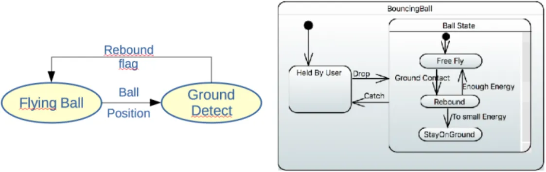
Figure 2. System side, Functional view with data flow and State Machine
(called directors). The second provides a more component-aware framework still relying mainly on programming lan-guages. The last one targets the definition of xDSML (eXe-cutable Domain Specific Modeling Language). Our proposal could be implemented using these frameworks especially the BCOoL (Behavioral Coordination Operator Language) proposal from GEMOC [9]. This will be the purpose of future work.
The Distributed Architecture for Controlled CO-SIMulation, DACCOSIM, [10] is an FMI-compatible Master Algorithm generator. DACCOSIM targets FMI-based simu-lation and the cooperation of multiple FMI simusimu-lation units. To support variable step size, the necessary error control and rollbacks are achieved through a hierarchical and distributed control architecture. At each step, simulation data commu-nications also occur, but directly between FMU pairs in a fully decentralized fashion. With respect to this approach, we feel the need for a few improvements: (i) integrate the co-simulation in a wider model-based systems engineering approach; (ii) make explicit the parameters of the simulation and (iii) isolate the rollback and have it controlled by the master algorithm.
4. Modeling co-simulation
In this section we present a modeling of the bouncing ball example that distinguishes between the system model and the simulation model in a manner that complies to the FMI/FMU standard directives, while allowing for a clean separation of concerns between the system related issues and the co-simulation concerns.
We start with the design of the system model that contains the description of the bouncing ball behaviour. This model is split into two functions : the ”Flying Ball” and the ”Ground Detection”. Further on, we overview the simulation model, that embeds components that give a fine description of the various phases of the bouncing ball behaviour, and rises the need for a master algorithm that coordinates the simulation and ensures the coherent information exchanges between the various components, even in the presence of IP protection.
4.1. System model
From the point of view of the systems engineer, the bouncing ball movement is composed of two simple func-tions: (i) the Flying Ball (up or down) and (ii) the Ground Detect.
The coordination between both is such that : (i) The Flying Ball function sends the ball position to the Ground Detect function. (ii) The Ground Detect function receives the ball position and detects if it touches the ground. In response, the Ground Detect function returns a rebound flag at true if there is still enough energy or false otherwise. In that last case, the ball enters the ”StayOnGround” state, as illustrated in the following figure Fig. 2.
At the system level, the actual behaviour corresponding to states such as Free Fly or Rebound is not important. We are only focusing in this paper on the overall (system) view of this behaviour.
4.2. Simulation model
In this section, we start with the system model described previously and we aim at building the operational simulation model. The purpose is to make explicit all the elements needed to conduct a co-simulation that are usually hidden in the co-simulation frameworks. The simulation model pro-vided in Fig. 3 is constructed based on the functions issued from the system model. All these functions are directly written with the help of the JavaFMI framework [4]. We would therefore need to express the Flying Ball and Ground Detect functions. However, as the simulation has to handle the heterogeneous nature of the movement corresponding to these two functions, we need to combine the two behaviour models. In order to do so, we define a Master Algorithm, whose role is to drive the switch between the two movement modes corresponding to each of these functions.
Moreover, the hybrid nature of the overall system (con-tinuous during the Free Fly phase and discrete at Re-bound) requires a dedicated mechanism to manage the time according to the expected simulation data precision. This mechanism should allow the Master Algorithm to properly adjust the size of the simulation step, based on the charac-teristics of the movement while avoiding the Zeno effect. In
Figure 3. Model Simulation side, Functional view with data flow
this context, the rollback mechanism is typically used. We briefly overview in the following the characteristics of these components.
Figure 4. Bouncing Ball, Model Simulation side, State Machine Ball
4.2.1. Flying Ball. The behaviour of the flying ball consists in a uniformly accelerated motion in a uniform gravitational field. The up and down movement takes place on the vertical and is described by simple physical laws. The ball can either be in Free Fly, Rebound or StayOnGround mode. At rebound, a horizontal symmetry is applied to the ball speed vector and the ball energy decreases, thus decreasing the velocity, to eventually reach a situation where the ball stays on the ground.
4.2.2. Ground Detection. Given that we simulate the bouncing ball – which is a continuous process – in a discrete manner, it may lead to situations where the ball appears to be under the ground if the ball crossed the ground between two simulation instants. The ground detection behaviour identifies whether the ball touches the ground or not, based on the ball position. For the simulation, we consider that the ball touches the ground if its position is lower than a predefined parameter, that defines a rebound zone, as opposed to the free fly zone located above it as shown in the following figure. During the simulation, the activation of the ground detection is discretized. If the rebound zone is very large with respect to the simulation step, then the ball would prematurely rebound, and the ball would never actually touch – or get really close to – the ground. On the
other side, if the rebound zone is narrow with respect to the simulation step, it may happen quickly that the ground detection is activated while the theoretical ball position is under the ground. In reality, a good compromise between the two values is needed, and anyway the size of the simulation step is rarely only depending on this part of the system. As a consequence, we need a mechanism capable of handling the “under the ground” situation of the ball. One way to do it, is through a rollback process.
Figure 5. Bouncing Ball, Ground Detection zones
4.2.3. Rollback. Once an “under the ground” ball position is identified, the rollback mechanism is activated and it consists in going back to the previous simulation step and running again the simulation with a smaller simulation step. This is a general strategy that can be applied in any simulation in which the simulation step size may vary: perform a simulation step and check whether the system state is coherent or not. If not go back to the previous step and re-run the simulation with a smaller step until the system state is coherent.
In our case, with a new step, one of the followings may happen as shown in the previous figure:
• the ball is underground – we have to go back again and consider an even smaller simulation step;
• the ball is in the rebound zone– the master algorithm will have to take care of the rebound;
• the ball is in the free fly zone.
In order to avoid the Zeno effect, we need to intro-duce constraints on the physical model. More precisely, the derivative of the position (i.e., the speed) must be bounded which is the case with finite energy systems. In our case, energy is not bounded as we consider uniform gravity which
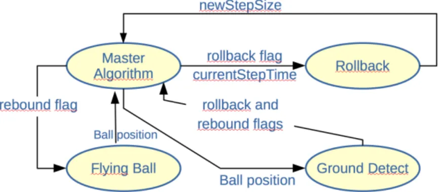
Figure 6. Overview of the Master Algorithm
is a coarse approximation at the level of the ground of the real gravity behavior. But, as the ball will reach the ground, the maximum speed is the one at ground level and thus the derivative is bounded. For a given precision, we can compute iteratively the simulation step value in a finite number of iteration and thus avoid the Zeno effect.
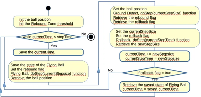
4.2.4. Master Algorithm. The master algorithm orches-trates the calls towards the components handling the fly-ing ball, the ground detection, and the rollback. These components are implemented as FMUs whose execution is managed by this algorithm. The data flows describing the exchanges taking place at this level are described by the activity diagram in Fig. 6.
Beyond the obvious goal of having a master algorithm that works correctly we aim at (i) keeping this master algorithm as simple as possible and investigate whether it is possible to automatically generate it (completely or partially), and (ii) considering IP protection concerns. At this level, the IP protection is ensured by the fact that a FMU is an executable code. Although it is in principle possible to reverse engineering this executable code. This is both ex-pensive and hard to exploit, given the important size of such applications. Moreover it would lead to structure flattening that would make it practically impossible to exploit.
The master algorithm is specific to each system, in par-ticular ours is specific to the example of the bouncing ball. Nevertheless, the need to orchestrate rollbacks is present in most of the systems and through it the example helped us to gain experience on this aspect.
5. Future work and conclusion
In this work-in-progress paper we have illustrated, through a simple case study, some of the difficulties that arise when building co-simulations as required in the devel-opment of a complex system. Even when a dedicated frame-work such as FMI/FMU is available a number of questions remain: (i) how to model the simulation components; (ii) how to define the master algorithm; (iii) how to take into account the rollback function.
This proposal illustrates that it is possible to include the co-simulation in a holistic, model-based, systems engineer-ing approach. In particular, it is possible to go from the system model to the co-simulation model by adding two main functions: Master algorithm – for orchestrating the individual simulations; and the Rollback – for adjusting the simulation step size of the various isolated simulations.
In addition, we have explored the possibility to export the rollback function outside the concerned model (i.e., the Flying ball function). We have also created a specific and efficient code for the Master algorithm function. Finally, we had the ability to choose the execution order of the different functions.
Based on these results, there are several paths where this work will be taken over. One direction would be to go further with the integration of the requirements specific to the EE and eventually allow for the existence of two (or more) master algorithms that cooperate. In order to do so, beyond the necessity to enable communication mechanisms between the master algorithms, there needs to be a way to coordinate the rollbacks performed in various parts. Coor-dinating several rollbacks could induce major performance increases at simulation time, as it could avoid performing useless rollbacks.
Some of the co-simulations are done in the context of the development of applications that are subject to certification. Currently the certification process related to aeronautics systems does not look into the preliminary results obtained through simulation. One of the reason for this is that there is no formal link between the simulated model and the generated code. One of our future work directions is to establish traceability links between the system model, the co-simulation model and the execution code. This would be a first step towards including the simulation into the certification process.
Acknowledgements
The authors would like to thank the MOISE project members for its support as well as the French Commissariat G´en´eral `a l’Investissements(CGI) and the Agence Nationale de la Recherche (ANR) for their financial support in the frame of the Programme d’Investissement d’Avenir (PIA).
References
[1] I. 24765:2010, “Systems and Software Engineering – Vocabulary.” [2] D. C. Schmidt, “Guest Editor’s Introduction: Model-Driven
Engineer-ing,” Computer, vol. 39, no. 2, pp. 25–31, Feb 2006.
[3] M. Association, “Functional Mock-up Interface for Model Exchange and Co-Simulation,” 2014, available at http://fmi-standard.org.
[4] T. S. U. of Las Palmas. SPAIN, “Java Functional Mock-up Interface for Co-Simulation,” available at https://bitbucket.org/siani/javafmi/ wiki/Home.
[5] C. Bertsch, E. Ahle, and U. Schulmeister, “The Functional Mockup Interface - seen from an industrial perspective,” 2014, in: Proceedings of the 10th International Modelica Conference 2014, Lund, Sweden. [6] J. Eker, J. W. Janneck, E. A. Lee, J. Liu, X. Liu, J. Ludvig, S. Neuendorffer, S. R. Sachs, and Y. Xiong, “Taming heterogeneity -the Ptolemy approach,” Proceedings of -the IEEE, vol. 91, no. 1, pp. 127–144, 2003.
[7] C. Hardebolle and F. Boulanger, “Modhel’x: A component-oriented approach to multi-formalism modeling,” in Models in Software Engi-neering, Workshops and Symposia at MoDELS 2007, Nashville, TN, USA, September 30 - October 5, 2007, Reports and Revised Selected Papers, 2007, pp. 247–258.
[8] B. Combemale, C. Brun, J. Champeau, X. Cr´egut, J. Deantoni, and J. L. Noir, “A Tool-Supported Approach for Concurrent Execution of Heterogeneous Models,” in 8th European Congress on Embedded Real Time Software and Systems (ERTS 2016), Toulouse, France, 2016. [Online]. Available: https://hal.inria.fr/hal-01258358 [9] M. E. V. Larsen, J. DeAntoni, B. Combemale, and F. Mallet, “A
be-havioral coordination operator language (bcool),” in 18th ACM/IEEE International Conference on Model Driven Engineering Languages and Systems, MoDELS 2015, Ottawa, ON, Canada, September 30 -October 2, 2015, 2015, pp. 186–195.
[10] V. Galtier, S. Vialle, C. Dad, J. Tavella, J. Lam-Yee-Mui, and G. Plessis, “FMI-based distributed multi-simulation with DAC-COSIM,” in Proceedings of the Symposium on Theory of Modeling & Simulation: DEVS Integrative M&S Symposium, part of the 2015 Spring Simulation Multiconference, SpringSim ’15, Alexandria, VA, USA, April 12-15, 2015, 2015, pp. 39–46.
![Figure 1. A schematic view of an FMU [3].](https://thumb-eu.123doks.com/thumbv2/123doknet/14398298.509537/4.918.472.839.435.630/figure-schematic-view-fmu.webp)