Publisher’s version / Version de l'éditeur:
Geotechnique, 16, 3, pp. 187-208, 1966-11-01
READ THESE TERMS AND CONDITIONS CAREFULLY BEFORE USING THIS WEBSITE.
https://nrc-publications.canada.ca/eng/copyright
Vous avez des questions? Nous pouvons vous aider. Pour communiquer directement avec un auteur, consultez la
première page de la revue dans laquelle son article a été publié afin de trouver ses coordonnées. Si vous n’arrivez pas à les repérer, communiquez avec nous à PublicationsArchive-ArchivesPublications@nrc-cnrc.gc.ca.
Questions? Contact the NRC Publications Archive team at
PublicationsArchive-ArchivesPublications@nrc-cnrc.gc.ca. If you wish to email the authors directly, please see the first page of the publication for their contact information.
NRC Publications Archive
Archives des publications du CNRC
This publication could be one of several versions: author’s original, accepted manuscript or the publisher’s version. / La version de cette publication peut être l’une des suivantes : la version prépublication de l’auteur, la version acceptée du manuscrit ou la version de l’éditeur.
For the publisher’s version, please access the DOI link below./ Pour consulter la version de l’éditeur, utilisez le lien DOI ci-dessous.
https://doi.org/10.1680/geot.1966.16.3.187
Access and use of this website and the material on it are subject to the Terms and Conditions set forth at
Pore pressures at a penetrating frost line and their prediction
Williams, P. J.
https://publications-cnrc.canada.ca/fra/droits
L’accès à ce site Web et l’utilisation de son contenu sont assujettis aux conditions présentées dans le site LISEZ CES CONDITIONS ATTENTIVEMENT AVANT D’UTILISER CE SITE WEB.
NRC Publications Record / Notice d'Archives des publications de CNRC:
https://nrc-publications.canada.ca/eng/view/object/?id=a9d13534-0237-4505-a734-d1e61da96ecb https://publications-cnrc.canada.ca/fra/voir/objet/?id=a9d13534-0237-4505-a734-d1e61da96ecb
BY PERMISSION OF THE COUNCIL
EXCERPT PROM G ~ ~ O T E C I I N I Q C E . SEPTEMBER 19&?1.:
,A
Z.YZ
E
D
PORE PRESSURES AT
A
PENETRATING FROST
LINE AND THEIR PREDICTION
byP. J. 'WILLIAMS
PUBLISHED BY
T H E INSTITUTION O F CIVIL ENGINEERS
GREAT GEORGE STREET
-
LONDON, S.W.11966
The right of publication and of translation is reserved
Tlrc Insrilurio,~ qf Civil Engineers us a body is no1 responsible o i l l z ~ r f o r llze slolentenls made o r f o r the opinions cxprersed in rhofollowing pages
PORE PRESSURES AT A PENETRATING FROST LINE AND
THEIR PREDICTION
SYNOPSIS An apparatus has been constructed for deter- mining pore pressures developed immediately below a penetrating frost line. Tests have been carried out with natural soils, graded fractions, and ceramic discs under various confining pressures.
The 'air-intrusion value' of the same materials has also been measured. I t is shown that a relation- ship exists between the air-intrusion value for a given soil, and the pore pressure developed a t the pene- trating frost line. This can be explained from the effects of pore size in determining the radii of ice- water and air-water interfaces and the relationship suggests a convenient test for determining the sus- ceptibility of a soil to frost heave.
Un appareil a &ti. fabriqu6 pour dt-terminer les pressions d'eau dCve1oppi.e~ immkdiatement sous la ligne de pknktration du gel dans I'6chantillon. On a effective des essais avec des sols naturels, particules grades et des disques de ckramique sous diverses pressions.
La valeur d'intrusion de l'air (la pression de l'air ntcessaire pour rompre les mknisques capillaires) a kgalement kt6 determink. I1 est dt-montrii qu'il existe un rapport entre la valeur d'intrusion de I'air pour un sol particulier et la pression de l'eau dkveloppke sous la ligne de p&n&tration du gel. Cette relation peut etre expliqut-e par les effets des dimensions des pores dans la determination des rayons d'interfaces (menisques) glace-eau et air-eau, et la rapport propose un essai simple pour la determination de la susceptibilitk d'un sol au soulkvement dii au gel.
INTRODUCTION
Frost heaving in soils is the result of an increase in moisture content, as a result of migra- tion of water to the freezing layer. This additional moisture appears for the most part in the form of discrete lenses or layers in the frozen soil. The migration of water occurs as a result of the hydraulic gradient set up by a fall in pore-water pressure at the lower boundary of the frozen layer. I n this Paper, this boundary is referred to as the frost line and when advancing downwards as a penetrating frost line.
According to the well-known Thomson equation very small crystals in their own melt have a lowered freezing point and, a t the same time, the internal pressure of the crystals differs from the pressure of the liquid phase. In the freezing of porous materials the pores themselves limit the size of the ice crystals and similar effects are thus observed in the freezing of soils. The pressure difference between the ice and water phases in general finds expression, at least in part, as a fall in the pore-water pressure, and it is this fall in pressure which is res- ponsible for water migration to the freezing soil. The relationship between the pressures of the ice and water, freezing temperature and pore size have been discussed earlier (Williams, 1966(c)).
The pressure difference established on freezing, between the ice and adjacent water is given by
d(5iwA)
$ i - P w =
7
. .
. . . .
. .
(1)where
pi
= pressure of ice = pressure of waterA = area of ice-water interface (i.e. surface area of ice crystal(s)) V = volume of ice crystal(s) ai, = surface tension ice-water
* Research Officer, Soil Mechanics Section, Division of Building Research, National Research Council, Ottawa, Canada. Research Fellow, Nonvegian Geotechnical Institute, Oslo, 1963-1965.
1 88 P . J . W I L L I A M S
If for simplicity, the pores of the soil are considered as cylindrical capillaries and the ice- water interface as hemispherical, then when the interface is within a pore (from Eqn (1)) :
where r, = radius of the curved interface ( z radius of the capillary) I.
These equations have also been derived by Everett (1961) from theoretical considerations of the chemical potential of the ice and water phases. The stresses on the soil and the soil moisture conditions may be such that (pi-$,,) is less than that which follows from Eqn (2). This is the situation where an ice lens is forming. A similar equation then applies, but rC is replaced by 7 , the radius of an interface which is too large to occur within the pores. For the frost line to penetrate downwards it is required that ice-water interfaces pass through the pores. The value of
pi-$,
must then equal that given by Eqn (2) with rc having a value corresponding to the pores of the soil in question.The particular value to be understood by r, requires consideration. The pores of a soil are not regular capillaries but consist largely of wedge shaped or conical spaces such that curved interfaces with a wide range of radii occur. I t has been shown earlier that the inter- faces become progressively more curved (lie in smaller openings) as the temperature is reduced (VC7ilbams, 1966(c)). Since the temperature a t the frost line is the highest occurring in the frozen soil, it might be thought that the value of 7 , to be used in Eqn (2) to describe the situa- tion a t the frost line should be that corresponding to the largest pores of the soil in question. This is apparently not correct because the largest pores are isolated from one another by smaller openings or 'necks'. I t is probable that the penetration of ice further into the soil occurs solely by extension of already existing ice (Williams, 1966(c) and Helmuth, 1962). For ice to form in the largest pores, therefore, the temperature and pressure conditions must be such as to enable the ice to grow through the openings to these pores. Spontaneous nucleation of ice in the pores is very unlikely in view of their small size and the small supercooling involved. I t is therefore the size of the 'necks' which largely determines the value 7 , which is to be used in Eqn (2) to describe the pressure conditions a t the penetrating frost line. More precisely, for a penetrating frost line, the radius r, is that of the largest continuous openings (the soil is
considered to be uniformly packed in this consideration, such that cracks or other discon- tinuities are not considered).
The formation of an ice lens a t the frost line represents a pause in the penetration of the frost line, brought about because the temperature and/or pressure conditions are not a t once appropriate for development of ice-water interfaces with a radius sufficiently small to pass through the underlying pore 'necks'. The continued growth of the ice lens occurs by migra- tion of water from the underlying soil; when this takes place sufficiently rapidly or over a
sufficient length of time, a fall in the pore pressure occurs which is great enough for the ice- water interfaces (according to Eqn (2)) to advance further into the soil.
According to the well-known capillary equation (see e.g. Taylor, 1948) air replaces water in
a capillary when :
where
pa
= pressure of aira,, = surface tension air-water
r, = radius of capillary
The radius of the interface is slightly less than that of the pore because of the presence of an adsorbed (unfrozen) water layer on thc ~valls of the pore.
P O R E P R E S S U R E S A T A P E N E T R A T I N G F R O S T L I N E A N D T H E I R P R E D I C T I O N 189 I n soil mechanics terminology, the symbol u is normally used for the pore-water pressure. The symbols z t , and u , will therefore be used henceforth in this Paper for the pressures repre- sented by Eqns (2) and (3) respectively, with r, being defined for porous materials in the man- ner explained above. Combining Eqns (2) and (3) :
$i-ui - CJtw
.
.
. . . .
. .
$ , - ~ t u auw (4)
so that if a,, and a,, are known, measurements of 9 , - u , (Eqn 3) should allow prehction of
9 , - u i provided that the air-water and ice-water interfaces in both cases can be assumed to lie in the same openings (i.e. that r, is equal in the two cases). Two well-known types of soil test, the suction-moisture content (or pressure membrane) test and those involving measure- ments of 'capillarity' (or ' height of capillary rise'), are essentially concerned with the relation- ship shown in Eqn (3). However for reasons which are discussed later, neither gives values of $ , - u , which are suitable for comparison with values of 9 , - u , a t the penetrating frost line. Instead an apparatus incorporating features from both these types of test has been devised for obtaining appropriate values of
9,-zt,.
FREEZING EXPERIMENTS
General $rinci$le
The aim of the freezing experiments was to determine the pore water pressures a t the frost line when this is penetrating through the soil. These determinations were made on various soils and on ceramic filters, and with various total pressures on the sample system. I t will be shown also that under appropriate conditions, the pressure on the ice phase is predictable, and thus the quantity $ , - z t i may be obtained.
Measurements of pore pressure changes below a frozen layer have been reported by Beskow (1935), Ruckli (1950), Penner (1957, 1958) and others. I n general, mercury manometers have been used to measure the pore-water pressure a t the base of a specimen, or within it (Ruckli, 1950). Such manometers cannot be used when the pore pressures are lower than about -0.6 to -0.8 kglsq. cm. Furthermore the permeability of many soils is such that pore pressures measured a t a point some distance from the frozen layer may often be sub- stantially different from those a t the frost line.
I n the present experiments the specimen was placed on a filter of substantially different pore size to that of the specimen ; the specimen and filter were saturated with water and the water in the filter connected t o a pressure measuring device. The sample was frozen from the top down, and as the frost line penetrated downwards the observed water pressure fell. The permeability of the finer grained samples was such that the observed pressure was initially somewhat higher than that at the frost line. An abrupt change in the observed water pressures ensued when the frost line reached the base of the specimen and ice-water interfaces entered the filter. This was, of course, due to the hff erent pore size of the filter and was in accordance with Eqn (2). The water pressure immediately before this abrupt change is taken as that a t the penetrating frost line; as the frost line is then closely adjacent to the filter there is no significant difference between the observed pressure (that in the filter) and that in the soil pores adjacent to the frost line.
I t was also possible to determine values of
9 , - z t ,
for soils when the pore-water pressures would have fallen to less than -0.8 kglsq. cm-the limit to which direct observations could be made with the techniques of Beskow, Ruckli and Penner. In such cases the total pressure on the soil system was initially raised an appropriate amount above atmospheric pressure by raising the gas pressure round the sample. At the same time the pressure on the water in the pore-water pressure measuring system was raised by an equal amount (if this were not done drainage of the sample, of course, commenced). Even after the fall produced by freezing, theP . J . W I L L I A M S
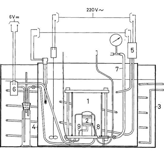
Key
1. Modified triaxial cell with steel walls, filled with compressed air or nitrogen 2. Sample on pedestal, freezing device in cap (see Fig. 2)
3. Thermally insulated outer tank with anti-freeze mixture, cooled by coil from external
refrigeration compressor
4. Perspex-walled inner tank with thermostatically controlled anti-freeze mixture ( +0.l0 C)
5. Temperature regulating device for inner tank, with contact thermometer, relays, stirrer and heating coil
6 . System for circulating freezing fluid through sample top cap, with reservoir, pump and thermally insulated tubing
7. Intake for compressed air or nitrogen with Bourdon gauge (0-12 kgisq. cm) 8 . Thermistor and/or thermocouple with connexion to recording instrument 9. Connecting tubing to pore-water pressure measuring device
P O R E P R E S S U R E S A T A P E N E T R A T I N G F R O S T L I N E A N D T H E I R P R E D I C T I O N 191 water pressure is still higher than that at which the water column in the connexion to the measuring device would rupture.
Apparatzbs
The specimen was mounted on the filter on a pedestal in a cell (Figs 1 and 2) constructed from a 'triaxial' cell (Andresen et al., 1957) as used in conventional strength tests. Freezing was brought about by circulation of an alcohol-glycerolmixture at about -S°C, in a coiled chan- nel in a perspex and dural cap placed on top of the sample (Fig. 2). In this way a fairly steady cooling occurred, the rate of freezing depending on the rate at which the fluid circulated through the coil. The circulation was achieved with a 12 V vehicle fuel pump and the rate of flow adjusted by a pinch clamp on the nylon connexion tube (Fig. 1). The basal filter usually had significantly coarser pores than the sample, care being taken that in the latter case the pores were not so coarse as to permit passage of soil particles. In some tests a filter with significantly finer pores was used.
The cell was placed in a bath filled with an alcohol-glycerol mixture, thermostatically controlled a t +O.l°C +O.O5"C. The bath itself was placed in a tank of the same Liquid, cooled to about
-
lZ°C, and thermostatic control was achieved by an electric heater and con- tact thermometer in the bath. The cell was filled with air or nitrogen, the pressure of which could be increased from a commercial cylinder. As a safety precaution, the original perspex wall of the cell was replaced by one of steel. The small size of the temperature gradients occurring between the cell wall and side of the sample, together with the gas-filled space between them, effectively minimized lateral heat exchange with the sample. The frost line was, accordingly, plane and horizontal. Temperature changes in the lower part of theCoiled channel for freezing fluid
\ Freezing fluid in + Preirozen
I
coarse- pored i.1t.r-1
Coarso-pored filter-
lhermocouple- --4
I _A&
~ e r o x filter'
Persper pcdestol\
Rings cut from bicycle . lnner tube --Thermistor
%To pore-pressure meosurcment system
Fig. 2. Enlarged view of pedestal assembly for freezing test with Aerox filter. A similar ar- rangement was used for tests on soils, except that the rubber rings did not bear on the sample, and in general a single thick membrane surrounded the sample
192 P. J . W I L L I A M S
specimen, due to external factors, were reduced by replacing the original brass pedestal by one of perspex (which has a much lower thermal conductivity).
Tests were carried out under either 'undrained' conditions, in which no water was allowed to enter the sample as the pore pressure changed, or under 'drained' conditions when a small quantity of water entered the sample from the measuring system. In the former case, pres- sures were measured either with a Bourdon gauge, or with a mercury manometer and, as the pressure fell, movement of water into the sample was prevented by repeated adjustment of a screw control and observation of a 'no-flow' indicator (see Andresen, et al., 1957).
When changes of pore pressure were expected to be small, a mercury or water manometer was used. Only 'drained' conditions were satisfactory in the case of soils giving a small pore pressure change (i.e. (0.2 kg/sq. cm) because a sufficiently responsive no-flow indicator could not be found. The manometer tube was 4.5 mm in diameter, thus avoiding any signi- ficant effects due to adhesion or the presence of the meniscus in the tube.
The sample was contained in one, or two, rubber membranes of the usual type. Expan- sion of the sample was thus permitted, and in most cases any confining pressure exerted by the membranes was too small to significantly affect the freezing process. In order to ensure that leakage of gas a t the base of the specimen into the pore pressure measuring system did not occur as the water pressure fell during freezing, an arrangement of rubber rings (Fig. 2) was necessary. In addition, silicone grease was applied between the membranes, and rings. The temperature a t the side of the basal filter was observed with a thermocouple, or thermistor, and could be recorded continuously. Although sensitive to changes of temperature of 0-001°C and possibly less, the thermocouple arrangement was such as to give only an indication (to perhaps $ 0.05"C) of the absolute temperature of the filter.
Nature and pre$aration of specimens
Natural soils, graded fractions and rigid ceramic filters (Aerox celloton VI,
&
in. thick)2 were used as specimens. The grain size composition and general characteristics of the natural soils are shown in Fig. 3. The graded fractions were prepared by elutriation from the glacio- fluvial silt @A (0stre Akers vei, Oslo). The grain-size limits given were calculated from Stokes' law. Examination of the 1.7 p to 6.4 p fraction under the electron microscope showed that a high degree of sorting was achieved. Application of ultrasound to the electron microscope specimen resulted in the appearance of a number of clay size particles (about 0.1 p in 'diameter'). These particles (which represented an extremely small part of thefraction) were therefore normally closely attached to the surface of the quartz particles. Preliminary tests showed that reproducible results could not be obtained if air was present, either free or in solution. Such air (which tends to be accumulated ahead of the frost line) affects the observed pore pressures in a variety of ways. Accordingly, in the tests on ceramic filters, these were thoroughly boiled before placing on the cell pedestal and basal filters.
In the case of the graded fractions and the natural soils it is necessary not only to de-air them completely, but also to make certain that no sedimentation occurs while, or after, the sample is placed on the pedestal. Such sedimentation would, of course, result in somewhat larger particles accumulating towards the bottom, and the observed pore pressures might then not be typical of the sample as a whole. I t was found that the most satisfactory procedure was to boil the material and place it on the basal filter (the supporting membrane being in place already) as a homogeneous slurry. The specimens were 1 to 2 cm in height. The two clay soils (Leda clay KNB (remoulded) and Winnipeg clay B) were cut from saturated samples and dissolved air could not be removed. The results obtained in these cases are therefore approximate. These specimens were about 2.5 cm in height.
Procedure. I n all tests the basal filter was first freed of air b y boiling, and the pore-water pressure measuring system flushed out with boiled water. After placing the sample on the pedestal the triaxial cell was closed and placed in the thermostatic bath. When the tempera- ture of the sample assembly had fallen to approsimately the same temperature as the bath, the cell was reopened and a coarse-pored stone filter, previously boiled and then frozen, was placed on top of the specimen. The top cap was placed on this, and connesions made to the circulation system. The cell was reclosed and replaced in the bath. The use of a prefrozen filter in this way was necessary to ensure nucleation of ice in the specimen. I t was helpful to have a small quantity of free water on top of the specimen before placing the filter. This ensured that ice growth in the pores of the specimen did not start before the pore pressures could be observed. The cell gas pressure and pore pressure were then raised (if appropriate) and circulation of freezing fluid through the top cap started.
For samples where a very small pore pressure change was expected on freezing, the cell was vented to the atmosphere to avoid errors due to thermal contraction and pressure changes of the air in the cell. As freezing progressed the pore pressure was generally noted about every three minutes, the gas pressure in the cell (if above atmospheric) being checked at the same time. I n tests carried out with slow7 freezing, undrained tests (involving a no-flow indicator) were impractical because of the frequent adjustment required, and the level of the mercury
in the manometer was observed a t longer intervals.
0,001 0.002 0.006 0.02 0.06 0.2 0.6 2
GRAIN SIZE (Equiv. Diam. r n m )
Fig. 3. Grain size composition and other characteristics of soils investigated:
WCB Undisturbed, mottled, montmorillonitic clay, Winnipeg
LC-KNB Remoulded Leda (marine) clay, mainly illite
S E Silt, mainly quartz and felspar particles thinly coated with iron hydroxides,
5% dark mineral content, mainly hornblende with some magnetic minerals. Colour of material 5 Y 612 (R.C.C.C. 1963)
0 A Glaciofluvial silt (mainly quartz). Particles >75 p removed by sieving
64/15-2E1~ Silt, mainly quartz and felspar. 5% dark minerals. Colour of material 6 Y 711 (R.C.C.C. 1963)
194 P. J . W I L L I A M S
After the ice had penetrated through the soil, the cell was reopened to check that freezing had taken place in the manner intended. In some cases the ice penetrated to the basal filter a t night, so that the mercury manometer was first observed the following day when con- siderable ice had formed in the basal filter. The expansion on formation of this ice resulted in a slight displacement of the mercury for which a small correction could be made to give the pore pressure established at the time of ice penetration to the bottom of the specimen.
I t may be noted that it was not necessary to make an airtight seal between the top cap and supporting membranes, because the fall in pore pressure induced by freezing is never great enough to draw air into the pores of the soil. The falling pore pressure also draws the mem- branes firmly against the sides of the sample.
Resztlts of freezing tests
Observations made during tests with ceramic filters are shown in Figs 4a-c. The gas pressure in the cell @,) and the pore-water pressure are shown as a function of time. The pore pressure is seen to fall, as freezing progresses, and then to rise after the value ui is attained, as
ice advances into the basal filter. Observations from a test on Leda clay are shown in Fig. 5a, and from a test on the 6.4-23 y silt fraction, using a finer filter below in the sample in Fig. 5b. I n this case the pore-water pressure shows a further fall as the ice penetrates this filter. A test on the 73-75 p silt fraction is illustrated in Fig. 5c (this was an undrained test).
The results of the tests are summarized in Tables 1 and 2, where the pore pressure at the penetrating frost line is expressed as a difference from the gas pressure (a 'confining' or 'all- round' pressure) on the sample 9,.
The temperature recorded at the side of the basal filter shows a rise associated with the commencement of ice growth in the basal filter. The magnitude of the temperature rise is related to the difference in pore size of the soil and basal filter and is therefore larger for soils with smaller pores, or for coarser filters (see Williams, 1966(c)).
*
Time, h r 3Fig. 4(a), (b), (c). Pore pressure (u) at the base of specimen and cell g a s pressure (p,) measured during penetration of frost line through Aerox filters. Also shown is the temperature recor- ded by a thermistor at the side of the basal fdter (see Fig. 2)
2 3 T i m e , h r
P. J . W I L L I A M S
1 2 3
Time, hr:
Fig. 5 . Pore pressure (u) and cell gas pressure (p,) measured during penetration of frost line. (a) Leda clay-the temperature recorded a t the side of the basal fdter is also shown. (b)
64-23 p silt fraction. A second fall in pore pressure occurs when the frost line reaches the basal fdter, which has frner pores than the specimen. (c) 73-75 p silt fraction
P O R E P R E S S U R E S A T A P E N E T R A T I N G F R O S T L I N E A N D T H E I R P R E D I C T I O N 197 3 2 3 T i m e , h r (b) 0 2 4 6 8 1 0 1 2 1 4 1 6 1 8 2(4 T i m e , h r (c)
P . J . W I L L I A M S
Table 1
Pore-water pressures at a penetrating frost line ( z L , ) , expressed as a difference from pressure on the ice, p i ( =pg +0.02) kg/sq. cm
Sample Rate of freezing (time required for penetration of frost line to base of specimen) Water intake during freezing Ct!. CJPZ Gas pressure in cell 9, kglsq. cnz (9,
+
0.02 - u , ) kglsq. c m Graded fractions 73 p t o 75 p1. .
. .
Natttral soils Silt E. .
. .
Leda Clay I(NB. .
. .
Winnipeg Clay B. .
..
Silt64/15-25b.. ..
I ~ r s m i n s 19 15 (ca.) 2 0 20 (ca.) 15 (ca.) 2 10 15 (ca.) 2 10 2 0 15 (ca.)1 Wet sieved through 75 p sieve. Value used in preparation of Fig. 9. Basal filter used of finer pore size than sample. Ice did not pass through clay pores.
Table 2
Pore-water pressure at a penetrating frost line. 'Undrained' tests with ceramic filters, type Aerox Celloton VI
Filter Rate of freezing (time taken
for penetration of frost line t o basal filter) m i n s
Interpretation of resz~lts of freezing tests
In the discussion at the beginning of this Paper, it appeared that the parameter of interest was
pi
-u, (i.e.pi
-pw, Eqn 2). It can be assumed that in many of the tests the pressure on the ice was substantially equal to the gas pressure :pi=$,.
For example, in the case of tests with ceramic filters it is obvious that a layer of ice on top of the filter, covering it more or less con- tinuously, must be under the gas pressurep,
(plus a small amount due to the weight of the top cap, viz. 0.02 kglsq. cm). The incorporation of further water molecules into the ice mass, as this extends into the pores, would be expected to occur in such a way as to most nearly approach thermodynamic equilibrium, i.e. that the ice in the pores would have the same pressure as that of masses larger than pore size. Theoretical reasons for assumingpi
zp,
in many cases are given in Williams, 1966(c), where experimental evidence for this being the case also for ice in the pores of a soil is presented. However, under certain conditions of freezing, discussed below, it appears thatpi#+,
for a t least part of the ice.Table 1 shows that in general the observed value of (pg+0.02-ui) kglsq. cm increased with decreasing grain size (and therefore decreasing pore size of the soil). For two relatively coarse materials an apparently wide range of values occurred. It is uncertain what signi- ficance should be attached to this, because the pressure difference represented by this range is in fact so small that were it to occur for finer soils (with higher values of (P, +0.020-z~,) kglsq. cm) it would be quite insignificant. However, the low values are found to be those for the tests which were carried out quickly and with intake of water, and there are several reasons why these might give low values. As noted above no-flow indicators were found not to be sufficiently sensitive to the small falls of water pressure occurring in these cases. Pre- sumably, changes of pressure are not fully transmitted a t once along the connecting tubing, but are to some extent taken up by friction and viscosity together with effects due to con- strictions in the connecting line and no-flow indicator. Although not initially considered, similar effects probably occur in the absence of the no-flow indicator and, because of the greater flow of water involved, t o an even greater extent.
An alternative explanation is that for these tests
9,
is not equal to (Pg+0.020) kglsq. cm but is somewhat greater. The additional volume of ice due to the water taken in by the sample requires expansion of the sample (frost heave) which might be resisted by the strength given by ice already present. This would result in an increment of pressure, C, on the ice such that :Pi
-
ui = (pg+
0.020 +C-
ui) kg/sq. cmI t could further be reasoned that the value of C is substantially reduced if freezing (and the associated expansion) occurs slowly. I t is well known that the resistance to deformation of ice and frozen ground is largely dependent on the rate of application of the deforming stresses.
While this component of pressure produced in the ice by its own expansion may be of con- siderable importance in broader consideration of frost heave, it appears unlikely that it has much significance for the present tests. The increase in volume of ice due to water intake only varies between about 0.2 to 1-5 times that associated with the normal expansion on freezing of the water already present in the sample.
A further possible explanation for the observation, that (p,
+
0.02 - u,) kglsq. cm was lower for rapid tests with water intake, is that ice penetrated downwards between the membrane and sides of the specimen causing premature ice growth in the basal filter. Temperature obser- vations showed that under such conditions there was a tendency for the membranes and sides of the sample to cool more rapidly than the interior and also for small vertical ice lenses to form between the membrane and sample. However, it is doubtful whether heat extraction upwards a t the sides of the sample would be rapid enough to cause sufficient ice growth in the filter to overcome the reduction of pore pressure associated with ice-water interfaces within the sample.200 P. J . W I L L I A M S
The temperature observations shown in Figs 4(a) and (b), and Fig. 5(a) are in agree- ment, within the limits of experimental accuracy, with those to be expected from theoretical considerations. The temperature T a t an interface between ice and water is given by (Williams, 1966(c)) :
where V , = specific volume of water
L = latent heat of fusion
T o is the freezing temperature where there is no significant curvature of the interface. I t is therefore 273.1S°K (=O°C) if the externally applied pressure were atmospheric. I t decreases by 0.0075"C per kglsq. cnl of additional pressure. The equation above is equivalent to one put forward by Schofield (1935). The observed temperature should be a t a minimum as the frost line reaches the base of the sample. I n the case of the test illustrated in Fig. 4(a) the tem- perature should then be -0.077"C (calculated using appropriate values in the equation). The observed value is in close agreement. On entering the pores of the coarse filter, the ice inter- faces are less restricted in size so that the pressure difference $, -u, decreases and the tempera- ture starts t o rise. Both effects apparently occur only slowly, perhaps because a significant quantity of ice must form in the coarse filter before near-equilibrium conditions are re-estab- lished. The rise in observed temperature may be limited by the situation of the thermo- couple on the cold side of the frost Line at this stage.
A tendency was observed for the temperature rise to commence somewhat before the rise in pore pressure. I t is to be expected that while the rise in temperature would commence as soon as any ice forms in the coarse filter, the rise in pore-water pressure would not commence until a considerable proportion of the ice-water interfaces had advanced from the sample pores into the filter. This effect is marked in the case of the Leda clay (Fig. 5a) and this sup- ports the above suggestion that ice may in some cases penetrate to the filter at an early stage through a crack or discontinuity in the sample considerably larger than pore size, but this does not necessarily prevent attainment of the value u, of the pore pressure.
The unexpectedly low value of
(9,
+
0-02-
u,) kg/sq. cm observed for the montmorillonitic clay Winnipeg B (in which the pores are extremely small) was found to be due t o substantial ice penetration to the basal filter along bedding planes (at a slight angle t o the filter) not visible in the specimen before freezing. Between the small ice layers in these planes, the clay remained ice-free.I n Table 2 the results of a number of tests with ceramic filters are shown and it is apparent that
(9,
+
0.02 -u,) kg/sq. cm is substantially independent of the value of (p,+
0-02) kg/sq. cm. This is also shown by a number of tests in Table 1 wherep,
was other than atmospheric. The relatively large scatter for the results from the tests with ceramic filters is probably due to the fact that the extreme importance of de-airing the sample and pore-water pressure system was not realized at the time the tests were carried out. Because the freezing process resulted fairly frequently in fracture or chipping of the ceramic filter, it was necessary to use three filters from the same production batch to complete the tests.AIR-INTRUSION VALUE DETERMINATIONS
Ap+aratus a?zd procedure
Following determination of
p,
- u , (= (p,+
0.02-
u,) kg/sq. cm) for the samples, values of the quantity 9,-u, were required to verify Eqn (4). For the determination of9,-ZL,
(Eqns 3 and 4) the apparatus shown (Fig. 6) was used. The sample, prepared in the same manner as for the freezing test, is placed in a perspex ring, and is separated from the underlying
P O R E P R E S S U R E S A T A P E N E T R A T I N G F R O S T L I N E A N D T H E I R P R E D I C T I O N 201 filter and water column by a membrane filter.3 The air pressure in the cell is raised by a series of increments applied over several minutes. Some drainage from the sample occurs due to compression as the air pressure is raised, and then a t a certain pressure there is a sharp acceleration of drainage.
This is due to the air-water menisci at the surface of the soil being overcome, such that air spreads throughout the sample displacing water. The membrane serves the same purpose as in conventional pressure membrane apparatus in that the pores of the membrane, because of their small size, remain waterfilled in the range of air pressurelwater pressure difference i n ~ o l v e d . ~ Direct passage of air into the water volume measuring arrangement is thus prevented.
Fig. 6 . Apparatus for determination of air-intrusion values
The apparatus is quite similar to a conventional pressure membrane apparatus, but with the essential difference that the membrane filter has a permeability of 5 x cmlsec (corresponding to a flow rate through the membrane of 3 x cu. cm/(sq. cmlsec) with a pressure drop of 0.010 kglsq. cm through the membranes) compared with 2 x 10-lo cmlsec (a flow rate of 6 x cu. cm/(sq. cmlsec) with a pressure drop of 0.050 kglsq. cm through the membrane) for a dialysis membrane commonly used in pressure membrane apparatus. This high permeability means (for the soils for which the test is appropriate) that following
3 Membrane Filtergesellschaft GmbH filter series hfF.
Preliminary tests with Filter MF 30, pore diameter 0.3 p, showed t h a t (as would be expected from E q n
P . J . W I L L I A M S
each increment of air pressure, the pore-water pressure throughout the specimen assumes an approximately uniform pressure in a few minutes at most, the high permeability of the mem- brane allowing rapid passage of water from the specimen.
The difference in pressure between the air and pore-water at which acceleration of drainage occurs,
pa
-ua, is called the air-intrusion value. The value of ua was given by the level of the water in the burette in relation to that of the sample surface, except for a small correction which might be necessary to allow for a pressure gradient in the pore water due to permeability effects.The fact that the air pressure may be raised quite rapidly (while the pore-water pressure remains definable) accounts for the well-defined point of air-intrusion (Figs 7 and 8). The apparatus as described can be used for soils having air-intrusion values up to about 2.5 kglsq. cm ; soils having higher air-intrusion values (those containing a high proportion of clay size particles) have too low a permeability unless very thin samples are used.
In pressure membrane tests such a well-defined point of air-intrusion is not found. Because of the low permeability of the membrane drainage is slowed down considerably. During the time involved, it is suggested that a time-dependent process of bubble formation and enlarge- ment occurs in pores which are isolated from others by narrower necks (remaining water filled at the value of pa-u in question). Further drainage ensues on account of this and obscures the sudden fall in moisture content associated with achievement of
pa
-ua and air intrusion through the largest continuous openings. Furthermore the time required for pressure membrane tests (where in practice a number of determinations are required for the establishment of a particular point on the pressure-moisture content curve) makes them unsatisfactory for the present purpose.The Statens Vaginstitut capillarimeter, widely used in Scandinavia, measures a basically similar air-intrusion value to that obtained with the present apparatus, but suffers from the disadvantages that it is only usable for a very limited range of air-intrusion values. I t also suffers from serious inaccuracies resulting from the passage of air through eventual discon- tinuities in the specimen and between the specimen and the glass walls of its container (cf. Graton and Fraser, 1935). Such air is prevented by the membrane from entering the water drainage volume measuring system in the present apparatus.
Theoretical considerations in the use of the present apparatus are discussed in another paper (Williams, 1966(b)) where a form of the apparatus suitable for use in field determinations is described.
In using the apparatus (Fig. 6) it is generally useful to first place a small quantity of free water on top of the specimen, and to draw this through the specimen by lowering the burette such that the water level in the burette is 10 or 20 cm lower than that of the sample surface. The observed rate of passage of water then indicates the rate at which the air pressure may be raised. I t is not necessary to wait until drainage ceases after each increment of air pressure. So long as the drainage resulting from raising the air pressure does not occur faster than that for the 10 or 20 cms water head, then the pressure gradient in the water and associated error in the air-intrusion value will not exceed a corresponding amount. Correction can, of course, be made for this error. The permeability of the sample may also be calculated from this prelimi- nary test (account being taken of the effect of the permeability of the membrane).
About 0-4 cu. cm of water is drained by compression of the membrane filter onto the bronze filter and by compression of the bronze filter onto the pedestal, before the air-intrusion value is reached. Some drainage also occurs if the soil is compressible because the air pressure acts as an effective stress. Such drainage may be reduced if necessary by a preliminary consoli- dation of the sample. For this, a rubber membrane is placed over the sample and held by the brass ring (Fig. 6). An air pressure somewhat below that expected for the air-intrusion value is then applied. After drainage has occurred, the cell is reopened and the rubber membrane cut away carefully. The test is then carried out in the usual manner.
204 P. J . W I L L I A M S
Results of air-intrusion value tests and their inter+retation
The results of air-intrusion value tests on the materials used for the freezing tests are shown in Table 3. As is to be expected, materials with finer pores (associated with finer particles) show higher air-intrusion values. The temperature a t which each test is carried out is also noted. The surface tension of water a,, (cf. Eqn (3)) is only slightly temperature- dependent (varying from 72.75 dynes/cm a t 20°C to 75.6 dyneslcm a t 0°C) such that the air- intrusian values would not be expected to show a marked temperature dependence. The permeabilities, however, are more temperature dependent as a consequence of viscosity changes.
Also included are results obtained with natural soils having a wide range of grain size. Although, perhaps, it is not immediately apparent, these soils also show well-defined air-intm- sion values (e.g. Fig. 7). The existence of a characteristic size of largest continuous opening (as discussed earlier) in such soils may seem surprising but it is understood when the small size of soil particles is considered. Even a piece of such soil a few cubic millimetres in volume contains many tens of thousands or hundreds of thousands of particles and is thus statistically representative of the sample (assuming it to be homogeneous in a macroscopic sense). Cor- respondingly there will be a characteristic size of largest continuous opening, repeatedly occurring in such a material, and it is this which determines the air-intrusion value. However,
Table 3
Air-intrusion values (pa - u,) and permeabilities
Sample
- -
Air-intrusion value
i
Permeability of Temperature(Pa-%) kglsq. c m sample, cmlsec. Graded fractions: 73 p to 75 pZ
. .
. .
6.4 p to 23 p.
.
. .
1 . 7 p t 0 6 . 4 ~..
. .
N a t u r a l soils Sandy Silt E. .
. .
Silt 64115-2jb. .
. .
@ A 0 p to 75 pZ. .
.
.
Leda clay I<NB3
. .
.
.
- - - -. . . - . . .
Aerox ~ e l l d t o n VI
. .
C.ern.mic. filter
1 The values given show variations due to differences in packing of the particles related t o thc timc the sample \{.as standing before the test.
2 Wet sieved through 75 p sieve.
3 From suction moisture content test and oedonlcter test.
P O R E P R E S S U R E S A T A P E N E T R A T I N G F R O S T L I N E A N D T H E I R P R E D I C T I O N 205 for such soils, the volume of water drained from the sample immediately after the air-intrusion value has been reached is less than in some graded fractions.
The air-intrusion value for the Leda clay ICNB is based on an interpretation of a suction- moisture content test and an oedometer test, and is taken from Williams (1966(a)). Direct measurement of the air-intrusion value was not possible with this material because of its very low permeability, and also because the apparatus could probably not be operated without leakage a t the high air pressure that would be involved.
DISCUSSION
Comparison of pore pressure at the penetrating frost line, a n d air-intrusion value
As discussed above, it appears that for freezing tests carried out slowly, or under undrained conditions,
(ps
+
0.02 -u,) kg/sq. cm =p,
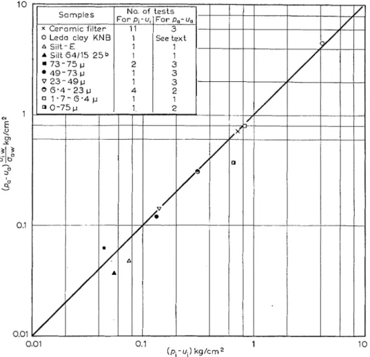
- u,.Using the values of (pi-zt,) from such freezing tests, and the observed air-intrusion values, (pa-u,), for the same materials, the experimental observations have been plotted in Fig. 9,
Fig. 9. Relationship between air-intrusion value (pa-ua) and pore pressure (expressed as p , -ui)
at a penetrating frost line. One or more tests were carried out on each sample to give average values shown
206 P . J . W I L L I A M S
where
(9,-zt,)
is multiplied by the factor O~~/U,,. A value of 30.5 dyneslcm was used foroiw (after Hesstvedt, 1964), and 75.6 dyneslcm or 72.75 dyneslcm for u,,, depending on whether
the air-intrusion value test was carried out a t
+
0.7"C or 20°C.I t is apparent that the experimental evidence substantially confirms Eqns (2) and (4). The fact that ($~~-zt,) is independent of $ J ~ in the freezing tests is further confirmation that Eqn (2) correctly describes the freezing process. According to that equation the only effect of changing
9,
(and thus $J~) could be through its effect on the interfacial energy uiW and the value of this is practically independent of pressure in the range of pressure here represented.Use of air-intrztsion valzte as a criterion of sztsce$tibility to frost heave
The establishment of the relationship between air-intrusion value and pore pressure a t the penetrating frost line suggests the use of air-intrusion value tests as a guide to the suscepti- bilitv of a kiven material-to frost heave. "
Frost heave as generally understood by highway engineers, is the volumetric increase of the soil which occurs as the result of uptake of water (which generally appears as ice lenses) by the freezing soil. The expansion associated wit11 the freezing of in-situ moisture is generally of relatively little significance. I t may be important under certain specific conditions but it is not considered here. The uptake of water occurs as a result of a hydraulic gradient through the unfrozen soil towards the frost line, established by a reduction of pore a t the frost line. I t is this reduction in pore pressure which can be predicted by the air-intrusion value test.
For small samples of negligible thickness, the pore pressure a t the penetrating frost line may be predicted from the product of the air-intrusion value and the factor uiw/uaw ( = 0 4 approx.) according to Eqn (4) as illustrated in Fig. 9.
Under field conditions the pore pressures a t the penetrating frost line will also depend on the overburden Dressure. Thus whether or not the material will show frost h e a v i n ~ " will d e ~ e n d on the overburden pressure, and also on the pore-water pressures in the underlying unfrozen layers. This fact, that the susceptibility to frost heaving is not alone a property of the material fier se but also of the situation under which it occurs. is often overlooked in the use of, for example, grain size distribution as a criterion. Frost susceptibility criteria are reviewed by Townsend and Csathy (1963(a)) and the same authors (1963(b)) have also hscussed the possible significance of pore size characteristics in relation to observed frost damage to highways.
The situation is best illustrated by an example. We assume that a silty material is avail- able and suggested as being satisfactory for use as highway sub-grade which must not be sub- ject to frost heave. The air-intrusion value (at 20°C), is determined to be 0.34 kg/sq. cm. The pore-water pressure zt,, a t the penetrating frost line is then given by
If
pi
were atmospheric pressure (0 kglsq. cm according to conventional soil mechanics termi- nology), then zt, would be -0.14 kglsq. cm. If frost heave occurs the ice, as explained earlier, must bear the pressure due to the weight of overburden y . x, where y= bulk density, and x = depth. y. %=pi, the pressure on the ice.5 Taking the bulk density of the frozen soil as 0.002 kglcu. cm for a penetrating frost line a t depth x cm, then a t that depth pi=0.002x kglsq. cm, and the pore pressure ztix is given b y :uix = (0.002x - 0.14) kglsq. cm
. . .
. . . .
(6) The pore pressure a t the penetrating frost line in this material is thus defined as a function of depth. Whether or not frost heave actually occurs will depend on whether or not higherThe rate of freezing in the ground is such that additional stresses would not in general be expected in the ice. However, under certain conditions (for example on sloping ground) they may occur and have an effect equivalent to an increased overburden pressure.
pressures occur in the neighbourhood of the frost line such that a hydraulic gradient is estab- lished towards it.
Information as to the pore pressures to be expected in the soil before freezing is therefore required. For the present example, we assume that a free water table occurs at 100 cm depth. The pore pressure (before freezing) as a function of depth x is:
ZL, = (
-
100+
x) cms of water = kgjsq. cm.
.
,1000
where uX=pore-water pressure before freezing at depth x cm. Water migration to the frost line occurs when :
26,
>
UlXi.e. the maximum depth x, to which frost heave can occur is that at which the pore pressure u,, = u, = u,,. From Eqns (6) and (7) :
or
X, = 40 cm.
This material is therefore only satisfactory for use at greater depths than this. This simple example is included here to illustrate the manner in which the field conditions of pore-water pressure and overburden pressure, together with the pore size characteristics (characterized by the air-intrusion value) determine whether or not frost heave will occur for a given material.
In practice, some additional considerations are likely to be necessary. Calculation of the initial pore-water pressure zc, at various depths from considerations of hydrostatic equilibrium and depth to the water table only is not fully justified in many cases, because of transient effects due to weather, the freezing process itself, etc. Secondly, while the agreement between the two sets of experimental results as a whole is good, in individual cases there are discrepan- cies which would leave room for significant variation in the predicted value of x,. These discrepancies may in fact be mainly due to the experimental observations in the relative diffi- cult freezing tests being of poorer quality than in air-intrusion value determinations. Further studies of the latter (Williams, 1966(b)) indicate that it is relatively easy t o obtain quite closely reproducible results for the air-intrusion value. I t seems likely that under field con- ditions as well the pore pressures developed a t the frost line may to some extent be influenced by several barely predictable factors. The natural variability of soils over quite small dis- tances must be remembered. The procedure outlined above is somewhat conservative in so far as frost heave will often be so slight as to have no importance at a depth somewhat less than that at which uix =ui. If ztiX is only slightly less than u, then the water migration to the frost line will often be so small that very little heave occurs.
I t appears that the air-intrusion value gives a quantitative and clearly definable evalua- tion, both theoretically and experimentally justifiable, of the susceptibility to frost heaving of a given soil material. I t thus appears to have considerable advantages over conventional methods of appraisal. The extent to which it may be necessary to use some safety factor to allow for uncertainties of the type outlined will depend on the degree of frost heave which could be tolerated, economic factors, experience gained in its use and other factors.
CONCLUSION
(1) The relationship has been established between the pore-water pressure at a penetrating frost line, in a given soil, and the pressure (the 'air-intrusion value') at which air will enter and spread through the pores of the same soil, displacing water from it.
208 P . J . W I L L I A M S
continuous openings through the pore structure of the soil, and that it is this size which deter- mines the pore pressure a t a penetrating frost line in a given soil.
(3) Measurement of the air-intrusion value of a soil is performed relatively easily and quickly, and thus provides a convenient method of predicting the pore-water pressures that will be developed at the penetrating frost line.
(4) I t has been shown how the occurrence of frost heave depends on this pore pressure and also on depth and ground water conditions.
ACKNOWLEDGEMENTS
Discussions with Dr L. Bjerrum, Director, and other members of the Norwegian Geotech- nical Institute are gratefully acknowledged.
REFERENCES
ANDRESEN, A,, L. BJERRUM. E. DIBIAGIO, and B. ICJZRNSLI, 1957. Triaxial equipment developed a t t h e Norwegian Geotechnical Institute. Norwegian Geotechnical Institute, Publication, 21.
EESKOW, G., 1935. Tjalbildningen och tjallyftningen med sarskild hansyn till vagar och jarnvagar.
Statens vagginstitut, Stockkolnz. Meddelande, 48. (Also published as Sveriges geologiska undersokning. Avhrnndlingar och ztppsatser. Serie C , 375, and translated by Tech. Inst. iVorth-Western Univ., Euanston,. Ill., Nov., 1947.)
EVERETT, D. H., 1961. The thermodynamics of frost damage to porous solids. Trans. Faraday Soc., 57: 9 : 1541-1551.
GRATON, L. C. and H. J. FRASER, 1935. Systematic packing of spheres with particular relation to porosity and permeability. J . Geol., 43 : 8 (Pt 1) : 785-909.
HELMUTH, R. A , , 1962. Capillary size restrictions on ice formation in hardened Portland cement pastes.
Proc. Int. Synzp. on the chewzistry of cement, 4. Wash. D.C., 1960, 2 : 855-869.
HESSTVEDT, E., 1964. The interfacial energy icelwater. ~Vorwegian Geotechnical Institztte. Publication,.
56, 7-10.
PENNER, E., 1957. Soil moisture tension and ice segregation. Highway Researclr Board. Wash. D.C. Bulletin, 168, 50-64. (Also National Researcl6 Coztncil, Canada. Division of Building Research. Research paper, 67.)
PENNER, E., 1958. Pressures developed in a porous granular system as a result of ice segregation. Highway.
Research Board, Wash. D.C. Special report, 40, 191-199. (Also National Reseavch Coztncil, Canada. Diuisiorz of Building Research. Research paper, 81.)
RCCC (ROCK-COLOR CHART COM>IITTEE), 1963. Rock-color chart. Geological Society of America, N e w Yorh.
R U C I ~ L I , R., 1950. Der Frost im Baugrund. W i e n . 279 pp.
SCHOFIELD, R. I<., 1935. The p F of the water in soil. 3rd. Int. Cong. Soil Sci., 2 : 37-48. TAYLOR, D. W., 1948. Fundamentals of soil mechanics. John W i l e y , N e w Y o r k , 700 pp.
TOWNSEND, D. L. and T. I. CSATHY, 1963(a). Compilation of frost susceptibility criteria up to 1961.
Ontario Joint Highway Research Progmm?rze. Report, 14, 27 pp.
TOWNSEND, D. L. and T. I. CSATHY, 1963(b). Soil type in relation to frost action. Kingston, Ont. Ontario. Joint Highway Research Progranzme. Repovt, 15, 69 pp.
WILLIAMS, P. J., 1966(a). Suction and its effects in unfrozen water of frozen soils. Proc. Int. Coqzf. on
Permafrost, 1. Lafayette, Ind. 1963. (In press.)
WILLIALIS, P. J . , 1966(b). .4ir intrusion value in soils and its measurement. iVorwegian Geotechnical'
Inslilztle. (In press.)
WILLIAMS, P. J., 1966(c). Unfrozen water in frozen soils ; pore-size-freezing temperature, prcssure relation- ships. Norwegin~z Geotechnical I~zstitztte. (In press.)