Comparison of Approaches for Determining the Failure of Stiffened Cylindrical Shells by
David J. Price
B.S. Mechanical Engineering North Carolina State University, 1991
M.S. Engineering
The Catholic University of America, 1999
Submitted to the Department of Ocean Engineering and the Department of Mechanical Engineering in Partial Fulfillment of the Requirements for the Degrees of
Master of Science in Naval Architecture and Marine Engineering and
Master of Science in Mechanical Engineering at the
Massachusetts Institute of Technology June 2002
0 2002 David J. Price. All rights reserved.
The author hereby grants to MIT permission to reproduce and to distribute publicly paper and electronic (-oifs of this thesis document in whole or in part.
Signature of Author
Department of Ocean Engineering and the Department of Mechanical Engineering May 15,2002 Certified by
David V. Burke, Senior Lecturer Department of Ocean Engineering Thesis Supervisor Certified by
Nicholas M. Patrikalakis, Professor Oceaa iK echanical Engineering Professor of Engineering Thesis Reader Accepted by
Ie i k'0 k r c idkperofessor of Ocean Engineering
_w .jhairman, Dep tpatfii Committee on Graduate Students Department of Ocean Engineering Accepted by
Ain A. Sonin, Professor of Mechanical Engineering Chairman, Department Committee on Graduate Students Department of Mechanical Engineering MASSACHUSETTS INSTITUTE
Page intentionally left blank
Comparison of Approaches for Determining the Failure of Stiffened Cylindrical Shells by
David J. Price
Submitted to the Department of Ocean Engineering and the Department of Mechanical Engineering in Partial Fulfillment of the Requirements for the Degrees of
Master of Science in Naval Architecture and Marine Engineering and
Master of Science in Mechanical Engineering
ABSTRACT
The thesis compares the analytical solution, two marine classification society design rules, and two design guides against experimental results for predicting the failure modes (general instability, axisymmetric buckling, and asymmetric collapse of the shell [lobar buckling]) and failure pressures of ring-stiffened cylinders
The analytical solution is first summarized based on several sources. The design rules for the classification societies and the design guidance from two sources are then presented with brief explanations for each one. The design rules used are: American Bureau of Shipping (Rules
for Building and Classing Underwater Vehicles, Systems, and Hyperbaric Facilities, 1990) and
Germanischer Lloyd (Rulesfor Underwater Technology, 1988). The design guides used were Society of Naval Architects and Marine Engineers (Submersible Vehicle Systems Design, 1990) and Massachusetts Institute of Technology Course 13A Professional Summer Notes (MIT 13A
Submarine Design Trends, 2001).
The United States Navy Naval Sea Systems Command, Submarine Structural Integrity Division supplied experimental data for four cylinders that covered the failure modes and allowed comparison between experiment and design rules / guidance.
The comparison of experimental to predicted data found that the design codes and design guides performed adequately in predicting axisymmetric yield and asymmetric buckling. The performance of the design codes and guides in predicting failure by general instability was unsatisfactory. For the experimental failures by general instability, the design codes and guides predicted significantly higher failure pressures than those experimentally determined; resulting in the design codes and guides actually predicting failure by axisymmetric yield in stead of general instability. These inconsistencies in the predictions of failure mode and pressures for general instability should be further explored to determine causes and corrections.
Thesis Supervisor: David V. Burke Title: Senior Lecturer
Thesis Reader: Nicholas M. Patrikalakis
Acknowledgements
I would like to thank Mr. William Will of the Naval Sea Systems Command, Submarine Structural Integrity division for providing the experimental data for the thesis and providing invaluable knowledge into the mechanics of cylindrical failures.
I would also like to thank Dr. David Burke for not only being a very supportive advisor and providing the impetus for the thesis, but for giving much needed and timely guidance throughout the analysis and writing processes.
Lastly I would like to thank Matt Graytek and Stephanie Norris for producing some initial programming of the design rules. These were very important starting points for my analyses.
This thesis is dedicated to:
My parents: William F. Price and Letitia M. Price and My wife: Shelly L. Price
Table of Contents
Table of Contents List of Figures List of Tables List of Appendices Chapter 1: Introduction 1.1 Failure Types 1.2 Concept Exploration 1.3 Analysis Techniques1.4 Design Rules and Guides Examined
Chapter 2: Overview of Ring-Stiffened Cylindrical Shells 2.1 Terminology 2.1.1 Material Properties 2.1.2 Geometry 2.1.2.1 Cylinder Geometry 2.1.2.2 Stiffener Geometry 2.2 Classification of Stiffeners 2.3 Stresses in Cylinders Chapter 3: 3.1 3.2 Chapte Analytic Solutions History of Analyses Current Theory 3.2.1 Axisymmetric Yield
3.2.2 Asymmetric Buckling (Lobar Buckling) 3.2.3 General Instability
r 4: The Design Rules and Analysis Tools 4.1 American Bureau of Shipping (ABS)
4.1.1 Axisymmetric Yield 4.1.2 Asymmetric Buckling 4.1.3 General Instability 4.2 Germanischer Lloyd 4.2.1 Axisymmetric Yield 4.2.2 Asymmetric Buckling 4.2.3 General Instability
4.3 Society of Naval Architects and Marine Engineers (SNAMV 4.3.1 Axisymmetric Yield
4.3.2 Asymmetric Buckling 4.3.3 General Instability
4.4 MIT 1 3A Professional Summer Submarine Design Trends 4.4.1 Axisymmetric Yield 5 6 6 6 7 7 8 8 9 11 11 11 12 12 12 14 15 17 17 18 19 23 24 27 27 27 28 29 30 30 35 35 36 36 37 38 38 38 E)
Chapter 5: Experimental Results 43
5.1 NAVSEA Test Cylinders 43
5.1.1 Cylinder 1.d 44
5.1.2 Cylinder 1.f 45
5.1.3 Cylinder 2.a 46
5.1.4 Cylinder 2.c 47
5.2 Calculation to Experiment Comparison 48
Chapter 6: Conclusions 53
6.1 Comparative Analysis Review 53
6.2 Agreements and Differences 54
6.3 Applications of the Models 55
6.4 Further Areas of Study 56
References 57
List of Figures
Figure 1: Cylinder and Stiffener Geometry 14
Figure 2: Basic Cylindrical Shell Stresses 16
Figure 3: Failure Pressure Ratio versus Slenderness Ratio 19
Figure 4: Coordinate System for a Cylindrical Shell 20
Figure 5: Test Cylinder 1.d Schematic 44
Figure 6: Test Cylinder 1.f Schematic 45
Figure 7: Test Cylinder 2.a Schematic 46
Figure 8: Test Cylinder 2.c Schematic 47
List of Tables
Table 1: Comparison of Design Rule Calculations to Experimental Results 48
Table 2: Cylinder 1.f Elastic General Instability Failure Pressures 50
Table 3: Cylinder 2.c Elastic General Instability Failure Pressures 51
List of Appendices
Appendix A: Codes for Test Cylinder 1.d 59
Appendix B: Codes for Test Cylinder 1.f 99
Appendix C: Codes for Test Cylinder 2.a 141
Chapter 1: Introduction
The widespread use of stiffened cylinders in the marine industry has generated many studies into the stability and failure of these cylinders and methodology for failure prevention. Of primary concern to entities involved with the use of manned submersible vehicles is the design of ring-stiffened cylinders; this type of stiffened cylinder is used for significant portions of the pressure hull. Over a hundred years of theoretical and experimental research has led to a general understanding of the mechanics of failure for these cylinders. Based on this research, marine Classification Societies, such as the American Bureau of Shipping (ABS), the American Petroleum Institute (API), NORSOK and Germanischer Lloyd (GL) have promulgated design rules to provide guidelines on the design and building of stiffened cylinders for safe operation. Other design and analysis theories and guidance are available in texts such as those published by the Society of Naval Architects and Naval Engineers (SNAME).
1.1 Failure Types
There are three primary types of failure of ring-stiffened cylinders. They are
axisymmetric yielding (AY) of the shell between stiffeners, asymmetric buckling of the shell between stiffeners (Lobar), and general instability of the shell and stiffeners (GI). Axisymmetric yield generally occurs when the shell is relatively heavy and the frames are closely spaced. Lobar buckling can occur when the shell is relatively light and the frames are strong and widely spaced. General Instability can occur when the cylinder is relatively long, the shell is thin and the frames are small. General Instability is very dependent upon eccentricities in the shell, which tend to lower the cylinder's resistance to the General Instability mode. [1]
As analyzed here General Instability is presumed to occur in the elastic region of the stress - strain curve of the material. Cylinders also fail by inelastic General Instability, which occurs at significantly lower pressures than that of elastic General Instability. Failure by this mode is not addressed by the design rules. Other modes of failure also exist such as multi-wave instability, which is a sub-type of General Instability. It can occur in both the elastic and
inelastic regions. Again the design rules do not address this failure mode. Several of the classification societies address stiffener tripping, which is the rotation of a stiffener away from perpendicular with the shell, however stiffener tripping is usually a precursor to general
instability and is not a separate major failure mode.
1.2 Concept Exploration
For this thesis, an emphasis was placed on exploring how the various design rules
predicted failure of cylinders that replicate modern submarine design (i.e. the shell was relatively thick compared to the diameter of the cylinder). This was facilitated by experimental failure data from the U.S. Navy's Naval Sea Systems Command (NAVSEA) Submarine Structural Integrity Division. The analysis was limited to ring-stiffened cylinders to remain consistent with the primary concern of the thesis. The test cylinders that were chosen had failed in all three possible modes, allowing for comparison of the design rules in all modes of failure.
1.3 Analysis Techniques
For the analyses, the design rules for the various classification societies and design guidance were programmed into MATHCADTM for consistency of approach, ease of symbolic representation, and quickness of computations. The analytical solution was also programmed into MATHCADTM for comparison. The experimental data from the four test cylinders were
then input into each computer code. The codes gave a failure pressure for each type of failure. The lowest calculated pressure was then considered the failure pressure and the corresponding mode was designated the failure mode. The failure modes and pressures were then compared against the experimental results with emphasis placed on agreement between codes and experiment on failure mode (first priority) and then failure pressure (second priority). If a different failure mode was predicted than that experimentally found for a particular cylinder, an analysis was performed for agreement between predicted failure pressures and also the closeness of the failure mode pressures.
1.4 Design Rules and Guides Examined
There were two classification society design rules examined: The American Bureau of Shipping (rules from Rules for Building and Classing Underwater Vehicles, Systems and Hyperbaric Facilities, 1990 Edition) (reference 2) and Germanischer Lloyd (Rulesfor
Underwater Technology, 1988 Edition) (reference 3). Design guides included: The Society of Naval Architects and Marine Engineers (SNAME) (Submersible Vehicle Systems Design, 1990) (reference 4) and the Massachusetts Institute of Technology (MIT) Course 13A Professional Summer (13A PS) Submarine Design Trends Course notes (reference 5) was also used. The 13A PS is based upon the 1967 version of the SNAME publication Principles of Naval Architecture (PNA) with some modifications determined by Harry Jackson (CAPT, USN Ret.). A third classification society, the American Petroleum Institute (API) was planned to be used, however the immediately available rules from API were not valid for the experimental data used.
However, API does have rules to cover the types of cylinders examined here.
Design of Powered Submersibles by William Nash (reference 6), Principles of Naval
Architecture, 1967 edition (reference 1), a David Taylor Model Basin technical paper by J.G. Pulos and V.L. Salerno (reference 7), and several journal articles from the Transactions of The Royal Institution of Naval Architects by S. Kendrick (reference 8) and C. T. F. Ross (reference
9).
In Chapter 2 a brief discussion on the terminology of ring-stiffened cylindrical shells is produced along with a short derivation of the basic stresses in these cylinders. Chapter 3 contains the summary of analytic solutions used to predict failure (the solutions are not re-derived), Chapter 4 has the summary of the design rules and guides from the various sources. Chapter 5 describes the test cylinders and then compares the results from experiment to the results predicted by the design rules and guides. Chapter 6 summarizes the results with recommendations for further study.
Chapter 2: Overview of Ring-Stiffened Cylindrical Shells
Ring-stiffened cylinders are the prevalent construction type in the mid-bodies of modern submersibles. The stiffeners provide additional strength to the shell that is required for the pressure differential between the external hydrostatic pressure and the internal, approximate atmospheric pressure. [6]
2.1 Terminology
The various classification societies use slightly different terminology for the cylinder geometries and properties. In the computerized design rules, the symbols used by each
classification society are generally used to avoid confusion between the published code and the programs. All of the codes require computation of the moment of inertia (I) of the ring stiffener and the moment of inertia (Ie) of an effective ring stiffener (the frame and some length of attached shell). The formulas for I and Ie came from [10].
The terminology can be divided into two categories: material properties and geometry. All stresses and pressures are in pounds per square inch (psi), lengths are in inches (in), areas are in square inches (in2) and moments of inertia are in inches to the fourth power (in4).
2.1.1 Material Properties
1) Modulus of Elasticity (E): The slope of the linear region of the stress-strain curve of a given material. For all of the calculations a value of 3 X 10⁷ psi (a common value for steel) was used. 2) Poisson's Ratio (v or p): The ratio of lateral strain to axial strain in a material. For all
3) Yield Strength (cy or fy or k): An arbitrary value for materials marking the onset of plastic
deformation of a material. This is usually considered the point of 0.2% permanent strain. This
value is of primary concern in the axisymmetric yield calculations. This parameter ranged in
value from 65,500 psi to 157,000 psi.
2.1.2 Geometry
2.1.2.1 Cylinder Geometry (see Figure 1)
1) Cylinder Length (L or Lb or L,): Overall length of the cylinder between supports. This varies by cylinder and is of primary concern for General Instability calculations
2) Shell Mid-plane Radius (R): Radius from centerline of cylinder to the shell mid-plane.
3) Shell plate thickness (t or tP or s or h): Thickness of the cylinder shell plating.
2.1.2.2 Stiffener Geometry (see Figure 1)
1) Length between Stiffeners (L or Lf or L,): Distance between centerlines of adjacent stiffeners.
This distance was assumed to be constant for each cylinder. This dimension is important for
both Axisymmetric Yield and Lobar Buckling.
2) Web Height (h,): Length of the web for 'T' stiffeners or the height of the stiffener for
rectangular stiffeners.
3) Web Thickness (t): Thickness of the web for 'T' stiffeners or the thickness of the stiffener for
rectangular stiffeners.
4) Flange Breadth (bf): Width of the flange for 'T' stiffeners. This value is set to zero for
rectangular stiffeners.
5) Flange Depth (d): Thickness of the flange for 'T' stiffeners. This value is set to zero for
6) Stiffener Depth (H): The distance from the shell to the end of the stiffener. This is the stiffener height for rectangular stiffeners and the web height plus the flange depth for 'T' stiffeners.
7) Faying Length (b): The distance of contact of the stiffener to the shell. It is equal to the flange width for 'T' and rectangular stiffeners; if 'I'-beam or wide-beam (WF) stiffeners are used, then equal to the flange breadth in contact with the shell.
8) Effective Length of the Shell (Le): A length of shell to be considered as part of the combined stiffener and shell used in the General Instability analyses. This length is usually a fraction of the stiffener spacing, but many times will be equal to the stiffener spacing.
9) Area of the stiffener (A): Cross-sectional area of the stiffener.
10) Effective Area of the stiffener (Aeff): Cross-sectional area of the combined stiffener and effective length of shell or a modified area of the stiffener (A) based on the location of the stiffener.
11) Moment of Inertia (I): Area moment of inertia of the dedicated stiffener, used by some codes as part of the calculation for the effective moment of inertia.
12) Effective Moment of Inertia (Ieff): Area moment of inertia for the combined stiffener and shell, used for General Instability calculations.
Figure 1: Cylinder and Stiffener Geometry Cylinder L
I
Stiffener d wH bf 2.2 Classification of StiffenersThere are several methods to classify stiffeners. Of importance to the analysis of cylinders is the location of the stiffener: either internal or external to the cylinder shell. Both types are used for cylinder construction; slight modifications to the design rules (concerning
effective areas and moments of inertia) are required based on the location. External stiffeners of equal size to internal stiffeners require more material because of the greater circumferential length but offer the advantage of freeing spacing within the cylinder for equipment / living space.
Another classification of stiffeners are field (light / non-heavy) and heavy (king frame) stiffeners. Heavy stiffeners are substantially larger than the field stiffeners and are used to reduce the effective length of the cylinder for general instability concerns. Field stiffeners are of uniform size, shape, and spacing. For the current analyses no heavy stiffeners were used.
2.3 Stresses in Cylinders
A brief discussion of stresses in cylindrical shells is required to set up the derivation of the structural mechanics in support of the analytical solution. As a starting point, a cylinder can be considered a thin-walled structure (shell) if the ratio of the mid-plane radius to the wall thickness is greater than ten. This assumption allows the determination of the stresses by statics
alone.[10] All of the cylinders considered are treated as shells. A second assumption in the analysis is to consider the hydrostatic pressure as constant across the cylinder.
Cylindrical shells, exposed to hydrostatic pressure, have two basic stresses imposed by the pressure: hoop stress and axial stress. The equations for the stress are:
1) Hoop (circumferential) Stress: U1, PR (1)
t
2) Axial Stress: 0- pR (2)
2t
Where p is the external pressure, R is the shell mean radius and t is the shell thickness. Figure 2 shows the derivation of these two equations.
The addition of ring stiffeners to the base shell complicates the hoop stress analysis by introducing non-uniform deformation of the shell in the radial direction. There is also a beam-column effect due to the pressure acting in the axial direction. These effects will be addressed in Chapter 3.
Figure 2: Basic Cylindrical Shell Stresses
1) Axial Stress
Axial force on a vertical section of the cylinder must equal the axial stress times the circumferential area.
Force balance: = 2
-7i-R-t-caxial
Which results in:
P-R aaxialV= 2
2) Circumferential (Hoop) Stress
The force on a transverse section of shell, with width b must equal the hoop stress times the shell area.
Force balance: Which results in:
P-2-R-b = 2-b-t-a P-R hoop ~-Axial Stress G~ .jPR 2t P P Hoop Stress Choo PR t
Chapter 3: Analytic Solutions
Analytic solutions have been proposed and proven for the three major failure modes of stiffened cylinders. This chapter briefly describes the theories and equations used in the experimental analyses.
3.1 History of Analyses
The failure of cylinders exposed to external pressure has been studied for almost 150 years. The first attempts at understanding cylinder behavior was done by experiment and
empirical relationships in the 1850's.[6] The first analytic solution for a non-reinforced cylinder was presented by G. H. Bryan in 1888.[9] The first analysis of a reinforced cylinder appeared in 1913 by R. V. Southwell, followed a year later by a solution to the elastic buckling of a thin shell proposed by von Mises.[6] In 1934 Widenburg proposed a solution for asymmetric buckling that is independent of the number of lobes of failure.[6] This equation is the one used in the current analysis. Solutions for axisymmetric yield were first put forward by von Sanden and Gunther in
1920.[9] Viterbo presented a modified version of Sanden and Giinther's solution in 1930.[9] Pulos and Salerno presented a solution that included the Sanden and GUnther solution, the Viterbo modification and a term to account for the bending stress in the cylinder caused by the axial pressure.[9] The Pulos and Salerno solution is used in this thesis. For elastic general instability, the first reported analysis was presented by Tokugawa in 1929. In 1954 A. R. Bryant developed a similar equation using a different methodology. [6]
Analytical work from the 1950's onward has focused on obtaining solutions for different boundary conditions and more fully reconciling the analytic predictions with experimental
and geometric properties. With the advent of power digital computers and the use of finite element analysis there has been great strides made in understanding the failure of cylinders.
3.2 Current Theory
For this thesis, analytic solutions were collected from several sources for the modes of failure. A comprehensive theoretical solution that addresses all modes of failure is not presented. Reference 6 provides a good summation of the currently used analytic solutions.
A first indicator of the failure mode of a cylinder is found by plotting the cylinder's slenderness ratio (1) against the ratio of the shell buckling pressure(pc) to the hoop pressure at yield(py) (y).[I] The equations for these factors are given below.
s 2 .( E) (3) 2 D PC (4) Py
Figure 3 shows the plot of W versus . If the slenderness ratio is less than approximately 1.14 the cylinder should fail by axisymmetric yield; if A is greater than 1.14 then the cylinder should fail by lobar buckling. If the shell and stiffeners are not of sufficient size, the cylinder may fail by general instability at a pressure less than that found in Figure 3. [1] By using two assumptions (the material is steel with u = 0.3 and Ls/D >> tP/D) it can be shown that: [1]
1.30 (5)
Figure 3: Failure Pressure Ratio versus Slenderness Ratio
The treatment of boundary / end conditions of the cylinder is a vitally important factor in the analytic solutions. The literature is full of discussion on what types of end condition to use, with the choices ranging from full clamped ends to simply supported ends. The extreme cases are hard to create in reality and therefore the experimental results tend to fall between the ranges of predictions. Experiments have shown that partially clamped cylinders provide significantly higher failure pressures than that predicted by mathematical models utilizing simply supported ends. [8] For this thesis, no discrete boundary conditions were required to be stated for input into the equations.
3.2.1 Axisymmetric Yield
As mentioned in section 3.1 axisymmetric yield has been studied since the 1920's. The solution summarized here was put forward by Pulos and Salerno in 1961. It is based on the previous works of van Sunden and Gunther and Viterbo and includes a previously not included "beam - column" effect due to the hydrostatic pressure acting in the axial direction of the cylinder.[7] The governing differential equation is:
2 t .8-1.6 1.4 1 .2 yieldi 0 .0Rucklfing 0.4 0.2 0 0.5 1 1.5 2 2.5 A
DL 4w dx
j
+ p-R 2 2 dx2 Et -. w R 2 = p, 12
2) (6) Where: E-t3 D 12-(1 - V2)The term pR represents the beam
2
D is the flexural rigidity of the shell
column effect. It makes the solution to equation (6) a non-linear function of pressure and was the term neglected in the earlier analyses of axisymmetric yield. Figure 4 shows the coordinate system used in reference 7 to derive the governing equation. x, p, and r are the axial, circumferential and axial coordinates respectfully with u, v, and w being the corresponding displacements. [7]
Figure 4: Coordinate System for a Cylindrical Shell
R I
/
/
1'
I'
1</
O
01 dXFollowing typical practice in the solution of non-homogeneous differential equations the general solution of the governing equation can be written as the sum of the solution of the homogeneous equation and a particular solution. [6] The solution to the homogeneous equation produces four roots (rX 4). By analysis, placement of the origin of the coordinate system to take advantage of symmetry, and trigonometric identities, the general solution can be given as:
pR2
w = Bcosh Ax + F cosh A, x - (1-) (7)
Et 2
where B and F are arbitrary constants which can be found by applying boundary conditions to the equation. [7]. After further mathematical substitutions several dimensionless parameters were
introduced into the solution to allow easier solving of the problem. Four of these parameters (Fl-F4) were transcendental functions based on the geometry of the cylinder. These functions were
originally graphed to allow for a relatively quick solution to be found for a given cylinder. Finally an equation for the failure pressure of a given cylinder was determined. This equation along with the dimensionless parameters is given below.
PC.!= - ) (8) 3 - + denoml - denom2 4 Where: denom := A2-F22 + F2-F4-(1 - 2-p- + F42-1 - p 2 0.91 2o iKF - - 2 F4 IF+ V 2 3 09 denom2:= 2-)A. F2 - p-F4-
-111:=~'~
2112:=~'~
2 8 :=~
3. ( 1 _ !l 2 ). _L_Ft
4 cosh (11 }'8 )2 - cos (11 2. 8 )2 F 1 := - . ---:---:---'-~---:---:--~---:---~ 8 cosh(11}'8).sinh(111'8) COS(112·8),sin(112·8) ---'---'-~+-~-~---'-~ 111 112cosh (11 1. 8 ),sin( 11 2. 8 ) sinh( 11 1. 8 ).cos( 11 2. 8 )
---'---'---'----'-+---'----'--~--'-112 111
F2:=---:---:--~---:---:---:---:---~
cosh (11}'8 ).sinh( 11}'8) cos( 11 2. 8 ),sin( 11 2. 8 )
-~----'---'---'-~ +-~-~---'-~
111 112
An iterative process is required for the general case where the parameter y is not zero. The
solving the equations for the failure pressure again. Usually only two to three iterations are needed for satisfactory convergence of the failure pressure.[7]
3.2.2 Asymmetric Buckling (Lobar Buckling)
Asymmetric buckling is characterized by circumferential lobes between ring stiffeners. As noted above this mode of failure will occur when the cylinder's slenderness ratio is relatively high. This can be further characterized by a relatively thin shell thickness and widely spaced stiffeners.[l] R. von Mises first proposed a solution to the buckling of un-stiffened cylinders under hydrostatic pressure in 1929. He assumed sinusoidal displacements in the axial and circumferential directions to enable solving of a set of linearized partial differential equations that represented the elastic action of the shell.[6] He eventually obtained the following equation for the buckling pressure:
4 2 2-_ -t1L R 2 7r-R Pvm :- E- R n2 + .5- - + - n + - (9) 2 -2 2 2 [_2
]L
( L) __ In (LThe buckling pressure is dependent upon the number of circumferential lobes (n), which must be an integer value. This fact requires an iterative process of varying n until the lowest pressure is determined.
In 1933 Widenburg solved the above equation in way that was independent of n. From test data the buckling pressures from the von Mises equation and the Widenburg approximation differ by no more than 3.5%. [6]. Further investigation into the bucking of stiffened cylinders determined that the Widenburg equation worked very well by replacing the length of the cylinder by the length between stiffeners. Therefore the Widenburg equation (equation 10), shown
2.2 t. 2.5
LB 2.42- (10)
- - 0.45 - 2)075
D
3.2.3 General Instability
General instability consists of the yielding of both the cylindrical shell and ring stiffeners. A cylinder may be susceptible when the stiffeners are undersized when compared to the shell thickness and the cylinder is relatively long.[6] General instability may occur in either the elastic or inelastic stress region of a material. Elastic general instability is the mode covered by the available literature and is addressed here. Inelastic general instability has been studied mainly by government laboratories and most of the knowledge of this failure mode is classified material and therefore unavailable to the present author. [11]
The first analysis of general instability was presented by T. Tokugawa in 1929. [6] His methodology considered the failure as a combination of the failure of the ring stiffeners and shell buckling with each taking place separately. [9] In the 1940's S. Kendrick used a strain energy methodology to determine the failure pressure. In 1953 A. R. Bryant used a simpler strain energy method and determined an equation similar to both Kendrick's and Tokugawa's. [1, 9] The Bryant equation is therefore used for this analysis and is shown below as equation 10.
E-t (n 2 1)-E-Ie PGI (. ) R 2 2 2 3 2 R .*L n - + - -n 2+ 2 Where: Lb
The first term can be considered the failure of the shell and the second term can be considered the failure of a combined stiffener and an effective length of shell. [6] This effective length has had much discussion in the literature over the decades. Bryant assumed the length to be the spacing between the stiffeners, but others have proposed various corrections based on the cylinder's geometric and material properties.[5] For this thesis, the effective length used was the stiffener spacing.
Similar to the von Mises buckling pressure determination, the number of circumferential lobes (n) must be found that minimizes the failure pressure. The number of circumferential lobes is usually between 2 and 4.[5] The factor 1 is the number of longitudinal lobes in the cylinder.
Chapter 4: The Design Rules and Analysis Tools
The two classification societies' design rules that were utilized were the American Bureau of Shipping and the Germanischer Lloyd rules. These were chosen for their availability, their different levels of simplification of equations, their coverage of the specific geometries of the experimental cylinders, and their inclusion of all three failure modes. The Society of Naval Architects and Marine Engineers Submersible Vehicle Systems Design and Principles of Naval Architecture (PNA) were chosen for analysis as SNAME is the primary design society in the United States and has comprehensive guidelines for cylinders. The MIT 13A Professional Summer Submarine Design Trends notes were used because of the author's familiarity and the complete analysis of the failure modes.
4.1 American Bureau of Shipping (ABS)
The ABS design rules, as delineated in the Rulesfor Building and Classing Underwater Vehicles, Systems and Hyperbaric Facilities (1990), give a brief and conservative approach for determining the critical / collapse pressures for each failure mode. The ABS design rules do not explicitly name the failure modes, but there are distinct equations for the three modes.
4.1.1 Axisymmetric Yield
This mode is designated the yield pressure at midbay and midplane of a cylinder. [2] The formula accounts for the major parts of the analytic solution, but uses single value functions for the shell parameters and does not explain the functions of each part of the equation. The rules do account for the difference between internal and external frames by squaring the mid-plane radius to stiffener radius ratio for external stiffeners. The base equation follows:
A1 - -G F:= 2 _ A + twt + A := A ) A:= A s R 2 0 := [3.(1 - v 2 Internal Stiffeners or External Stiffeners 4 L M : 0 Q:=2 2 cosh (2-Q) - cos (2-Q) sinh(2.Q) + sin(2.Q) G:= 2 (sinh(Q)-cos(Q) + cosh(Q)-sin(Q)) sinh(2-Q) + sin(2-Q) sinh(2Q) - sin(2-Q) sinh(2.Q) + sin(2Q) 4.1.2 Asymmetric Buckling
This is called the Von Mises buckling pressure for a cylinder. It is the Widenburg
approximation that is used by most of the classification societies. t GP'Y. R-Where (12) 2N-t-L 0
5 (t 2.42-E- --2-R) 3 (I- V24 -0.45-( t )2 2-R 2-R)
The ABS code then has a range of allowable pressures depending upon the ratio of Pm to Py. Below is the logic for the maximum allowable working pressure for inter-stiffener strength (P,). Further safety factors are then applied to lower the allowable pressure in practice.
PM PM PC:= - if - 1 c 2 P P - if I < < 3 m 2-Pm 6 Y Py 4.1.3 General Instability
For the elastic general instability, the ABS code uses the Bryant equation with an effective length not equal to one frame space. The effective length is given below.
Le := mi 0.75Ls The equation for the failure pressure is broken into three parts, but the
total is equivalent to the Bryant formula.
E-t E-Ie-A2(n) Pn](n):= --- A(n) + R 3 R -L (14) Where: (13)
4 A1(n):
K
A2(n) + 2 ) n2 + 2)2 A2(n) :=n2 _ I I"R LC 4.2 Germanischer LloydThe design rules for Germanischer Lloyd are from Rules for Underwater Technology (1988 edition). The rules address all three failure modes very thoroughly and flow charts are provided to aide in programming the code for computer use. These rules also address out-of-roundness up to a nominal value of 0.5% of the mid-plane shell radius by determining a reduced allowable pressure. [3]
4.2.1 Axisymmetric Yield
The code for axisymmetric yield resembles the Pulos and Salerno methodology with some additions to account for the transition of the material into the plastic range during yield. The methodology consists of first guessing a pressure lower than the failure pressure (the test cases used 1 psi as the starting point) then iterating through a series of equations to determine the shell stresses. If the determined shell stress becomes greater than 0.8 of the yield strength of the material, then a Secant Modulus of Elasticity (Es), a Tangent Modulus of Elasticity (Et) and a plastic range Poisson's Ratio (p ) is calculated and used to determine the other calculation factors. The determination of the integer m in equation (14) is described in the code below.
aI-LI 7 n-M2
pm=
aa-Co0-
1 L1~+
---
7~2
1M
Where: 4 C2 C3 s *R 2 R .s -vp
Must iterate on the integer m until trial is < trial2. By meeting this condition the minimum failure pressure is found (with the minimum m).
trial:= 71 trial2:= -(m + 1) HI := 1 + H4-fH22 -3-1 - vP2] H2:= (2 - vp) - (I - 2.v p)-K] H3:=
1
- 2-vP) - (2 - vp)-K0] Et H4 := 2 2 CI-C2 - vp .C3 I - P H22 .H4 Cl Hl( 2 N H32. H4
C2 -- H
H2- H3* H4
C 3 :4 1 +::H
C4 is not used for cylinders without heavy stiffeners.
C5 := u-L
1
2
Past = 2-s- E critical pressure, elastic, calculation factor
R 3- IF v2
p = 1 psi (arbitrary low pressure)
This is the actual starting point of the iteration. A pressure (p) is guessed; the code then calculates the failure pressure. If the failure pressure is greater than the guessed pressure, the applied pressure is increased by a set amount. This continues until the two pressures, p and pm are within a chosen delta of each other. This is essentially the method of Pulos and Salerno with a simpler method for iterating on the presumed pressure.
G:= Past 1G C6 := -- G 2 1G C7 := -- 1f + G 2 C8:= C5-C 6 C9 := C5- C7 2) s-L1 C90 A b (b -I:= A + -b + I - - b -F j s-LI L Li
0.91
1 - V
4 F -C5
cosh (C8)2 - Cos (C9)2
cosh (C).sinh(C8) cos(C9)-sin(C9)
C6 C
7
cosh (C8).sin(C9) sinh(C8).cos (C9)
C7 C6
cosh (C8)-sinh(C8) cos (C9).sin(C9)
C6 C 7 3 3 3 2 F4 V Cos(C9)-sin(C ) C7 cosh (C8).sinh(C8) C6
cosh (C8)-sinh(C8) cos (C9).sin(C9)
C6 C7
cosh (C8)-sin(C9) sinh(C8)-cos (C
9)
C7 C
6
cosh (C8)-sinh(C8) cos(C9).sin(C9)
C6 C
7
The functions F 1 through F4 are equivalent to those presented in the analytic solution.
3 1 - V2)
s2R2
shape factor
The following set of equations determines the stresses at the mid-bay of the shell.
-p.R ( '- S Gx:= G 0o + CIO-CI -F4 C:= Go. - I - C10-F2 + v-C10-C 1-F4) (l:-- 10,- (2- C 10*C 1 -F4 Go := Go.-( - C10-F2 - v-C10-C -F4) F2 =
K x
CYX
2 2
+Gi
~ - CTXcY
If the calculated stress is > 0.8k then the following equations are used to determine the material properties in the elastic - plastic region. The code is somewhat circular, the assumption was made to determine the strain (Fi) from the previously calculated stress then to find a new stress level by the equation given in the code.
G E a :=k-.8 + .2.tanh 5- -E - 4 e =-0.8 + 0..tn .- 4 k 5 kG< Es:=- 0.8 + 0.2. tanh 5. - 4 2 Et E.I - tanh 5-- - , - 4 1 1 Es P _2 2 E_ E +- E Et KI := 1 - KO + K02)
4.2.2 Asymmetric Buckling
For asymmetric bucking the Germanischer Lloyd code uses a modified version of equation 9. Therefore the dependence upon the number of lobes is not removed and should give a better estimate of the buckling pressure. The equation is given below.
E-s-n 1(n) pn1(n) R (16) Where: n 2 + 2 s2- n2 - + .12 2 Pnl(n):= 2 2 n2 + .5--1 2 L 4.2.3 General Instability
For elastic general instability, the code uses the Bryant equation with the effective moment of inertia based upon the effective length of shell as defined:
Letest := b +2Rs
Le := Letest if Letest : Li where L1 is the frame spacing
L, otherwise
The base equation for general instability also uses a modified radius (Ro) which is the radius to the centroid of the combined stiffener and effective length of shell. For this thesis no "heavy" or "king frame" stiffeners were used, however the code allows for these stiffeners with several more equations.
Where: E-s-P n2(n) po(n):= R n2 _-I)-E-Ie p1(n) := R0* LI 4 2 P2 - 1 + 0.5-k22 n2 + k22 2 L := L3 L
4.3 Society of Naval Architects and Marine Engineers (SNAME)
The SNAME code was taken from Submersible Vehicle Systems Design (1990). SNAME is not a classification society as ABS and Germanischer Lloyd, but it does provide many of the professional and technical resource material for naval architects in the United States. The current codes are revised versions of those found in the SNAME publication Principles of Naval Architecture (1967 edition), reference 1. The code addresses all three modes of failure with the least complex set of equations of those under current study.
4.3.1 Axisymmetric Yield
For axisymmetric yield, the methodology simplifies the analytic solution by using the older theory of von Sanden and GUnther instead of the solution put forward by Pulos and Salerno in reference 7. The methodology thus neglects the beam-column effect of the axial pressure. This is justified by designing the shell to yield vice buckle.[1]
t y 0.85 - B> 1 H (+ I Where: B:= t -t Ar + tw*t 0 := 10- 12.(l - P2)]4 N= cosh () - cos(0) sinh(0) + sin(0) I11*N FO.-i (Lf S2-R 50-t R) K 2 t A r + t~
3-sinh -. cos + cosh -sin sinh(0) + sin(0)
4.3.2 Asymmetric Buckling
For Lobar buckling, the code uses the Widenburg approximation equation that is independent of the number of failure lobes. This is the same as used by ABS.
2) 4 5
C
2
2tR 2-R 5 2.R)j (19) (18)I
Pb 2.42- E(
14.3.3 General Instability
For general instability, the code uses the unmodified Bryant equation; therefore the length of shell used in the moment of inertia calculation is one stiffener spacing. The code suggests that the critical value of n is between 2 and 4.
E-t M(4 (2 1)E-Ie Pcrl(n) := --R n2 M 2 -2 m2)2 R3-Lf 2 + (20) Where: 7r-R M:=-Lb
4.4 MIT 13A Professional Summer Submarine Design Trends
The Professional Summer notes are a compilation of design theories from Harry Jackson (CAPT, USN, Ret.) used to instruct the MIT course 13A students in the basics of submarine design. The actual purpose of the code is to evaluate a proposed submarine design given depth and material criteria; some modifications were required to provide the failure pressures. The failure equations for lobar buckling and general instability are generally from reference 1, however some small modifications have been made. A complete stress calculation is included for axisymmetric yield.
4.4.1 Axisymmetric Yield
The majority of the modifications to the original code were made to allow calculation of a failure pressure for this mode. The beginning code provided a required diving depth and therefore a pressure to withstand. It then performed a von Mises stress analysis on the structure, resulting with a shell stress. This shell stress (after modification by a safety factor) was then
compared to the yield strength of the material for acceptability. The code was modified to iterate on the pressure, with the failure pressure designated as the pressure at which the calculated stress was equal to the yield stress (without any modifications by safety factors). There was no distinct equation for the failure pressure. The following is the code used to determine
Gsy,
which is the shell stress. B:= tw-tp A + tw-tp Area ratio S n3-r1 - VP2a -=Lf (R t P)2 _ Slenderness Parameter cosh() - cos(0)sinh(0) + sin(0) Deflection coefficient
2. N110.25 3
P := A+ tw-t2.
A +tw~ P 3-(1 - _
1+f
Frame flexibility parameter
Frame deflection parameter
sinh -cos + cosh -sin(O
sinh(0) + sin(0) Bending effect (mem)
3__ .5 sinh -cos - cosh -sin
HE:= -2. f )-C (0 Bending effect (bend)
V
- 2 sinh(O) + sin(O)
K:= sinh(O) - sin(O) Bending efffect near frame sinh(O) + sin(O)
-P-R -$P .- - 1 + F.(HM + v-HE)] tp -P-R Gxxso:- tp .(0.5+ r-HE) -P-R C#<lo:= -- I t ' _ -P-R Gxxfo:= -tp ( CY4so Gxxso Gxxfo Gxxfi) -P- R #i-- 1 + .(HM - v-HE)] tp -P-R oxxsi:= --- ( 0.5 - F-HE) tp 3 0.5 3 0.5 -K 2 -v _ -P-R yxxfi:= -tp -r0.5+ FK 3 2 1-v 0.5 2 -v C74 := Gsy 7 2 C7SYM := ( 1 CI 2 2 -- '2 + 2 2 CYSYF := (C3 2 2 - G3-Y4+ a (YSYM 7SY := mal GSYF 4.4.2 Asymmetric Buckling
The equation for lobar bucking is the same as that used by SNAME and ABS and the analytic solution; it is the Widenburg approximation:
K 0.5 K E-C7sy:= (72 := y, SY aofi:= --- I -t -0.5 - F-.
2.5 2.42- E. 2. PcLB:= D (21) - 0.45 - 2)0.75 4.4.3 General Instability
For general instability, the Bryant equation is used with the effective length of shell given by the following method:
Leff:= LC-Fi + tw
Where
L: Lf - tw is defined as the clear length between the mid-bay and the stiffener
F1 4 cosh(ni.) 2 - cos(n2.0) 2 0 cosh(niO-)-sinh(nj.0) cos(n2-0)-sin(n 2-O) n i n2 n1 :0.5. -y n2 := 0.5-+Y y -.(R 2.V -3 -3 - 2 2-E tp
F1 is the first transcendental equation determined by Pulos and Salerno. The original
methodology required the pressure as an input to first determine the 0 function (it is the same as for axisymmetric yield) and then F1 was found. To provide for a simpler method, a series of
pressures that encompassed the predicted range of failure were input into the above equations and an average value of F1 was chosen from the resultant values. The F1 values changed by
approximately + 0.05 for each test cylinder. The effective length was then used to calculate the moment of inertia for the combined shell and stiffener. The number of lobes was set to be
between 2 and 4; the failure pressure was then found without other modifications to the Bryant formula. E-tp m4 PcGI. :-- R L-
#
_. 4 [ R ) 2 2- +M - [n i2 , 2]2 n 1 2 - I] -E.-lef + - jlf R3 Where: R m:= n.-Ls (22)Chapter
5:
Experimental Results
The various Classification Societies' design rules were tested against data collected from experiments conducted by the U. S. Navy in support of submarine design. Each society's design rules were used to determine the failure pressure and failure mode of each of the test cylinders. The resulting predictions were then compared to the experimental results. Of primary interest was agreement between the design rule prediction and experiment on the mode of failure, followed by the closeness of the predicted failure pressure to the actual collapse pressure.
5.1 NAVSEA Test Cylinders
The test data was provided by the Naval Sea Systems Command submarine structures unit (SEA 05P2). Four test cylinders were selected that covered the range of examined failure modes. The cylinder diameter to thickness ratios (D/t) fell between 112 to 198, modeling typical submarine D/t ratios. Two of the cylinders had internal stiffeners while the other two cylinders had external stiffeners. All four test cylinders had built-up end stiffeners with a combination of slightly different spacing and / or larger stiffener dimensions than the uniform field stiffeners. These end stiffeners were designed to prevent shell yielding in the end bays due to increased stress levels associated with the boundary conditions. It was estimated that without the end stiffeners a 4-5% reduction in axisymmetric yielding pressure could occur. None of the end stiffeners met the classification societies' requirement for a "deep" stiffener. None of the design rule codes allowed for these variable stiffeners, therefore the non-uniformities were disregarded and the end stiffeners treated as field stiffeners. The four cylinders are described below.
5.1.1 Cylinder 1.d
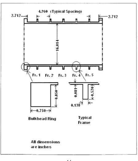
Cylinder 1.d was a machined cylindrical shell with rectangular external ring stiffeners. The material was high strength steel with a yield strength of 80,000 psi. Figure 5 shows the schematic of the cylinder. The boundary conditions consisted of one end being fully fixed; the other end had all freedoms fixed except for axial displacement (these conditions conflict with the design rules assumption of completely clamped ends). External hydrostatic pressure was applied including axial line load to simulate load on the end plate. The experiment tested the ability of the design rules to predict elastic shell bucking (Lobar buckling). The experimentally
determined collapse pressure was 633 psi with failure by asymmetric (Lobar) buckling. Appendix A has the analysis of predicted failure for this cylinder.
Figure 5: Test Cylinder 1.d Schematic
4.260 1Typical Spacing}
2.,2 1
[I1n
Kn
n
- i 2.10.138
Bulkhead Ring Typical Fi ame
All dimensions
5.1.2 Cylinder 1.f
Cylinder 1.f was a cylindrical shell with internal tee stiffeners of welded construction. The material was high strength steel with a yield strength of 98,500 psi. The boundary
conditions consisted of 4.0 inch steel plates attached with full fixity to the end of the adaptor ring on the model. External hydrostatic pressure was applied. This test cylinder was used to predict failure by elastic general instability. There was no experimental elastic collapse pressure;
therefore the critical pressure was calculated by two separate, reliable analysis programs with the results being 4858 psi (with 3 waves) and 4953 psi (with 3 waves). The test cylinder actually failed by inelastic general instability at a pressure of 2200 psi. Figure 6 shows the cylinder dimensions and Appendix B has the analysis of predicted failure for this cylinder.
Figure 6: Test Cylinder 1.f Schematic
A Detail 'A ___ I~I 7 -C I D Frames 1 &15 Adaplor Ring M-2 & IQI-2-0 Detail T' Frarnes 2.14
TABLE OF DIhENSION S (in&hes)
L A B C E F G H J K L M N P ( R S
5.1.3 Cylinder 2.a
Cylinder 2.a was a machined cylindrical shell with external tee stiffeners. The material was high strength steel with a yield strength 65,500 psi. Figure 7 shows the schematic of the cylinder. The boundary conditions consisted of end closures made of 3.0 inch steel plates attached to the idealized adaptor ring with full fixity. External uniform hydrostatic pressure was applied to the model. This cylinder was used by the Navy to predict end bay failure (shell
collapse influenced by end bay design). This is a specific example of axisymmetric buckling and was used as the axisymmetric model for the classification society rules. The experimental
collapse pressure was found to be 921 psi by axisymmetric collapse in the second bay from the adaptor ring. Appendix C has the analysis of predicted failure for this cylinder.
Figure 7: Test Cylinder 2.a Schematic
10.64 0.903 0.903 5 1.366 .01 7 -0.0858 k2 Adaptor Ring 4- 0.044 0 04
Typicat l Damies Ei lai
All dimensions are inches 00 r--CD 6 &-0.399-j -T 7r'Z--- 2 0.044 CI> End H ames
5.1.4 Cylinder 2.c
Cylinder 2.c was a fabricated cylinder with internal ring stiffeners. The base material was high strength steel with a yield strength of 157,000 psi. Figure 8 shows the schematic of the cylinder. The shell was cold rolled and fabricated with a deliberate out-of-roundness
imperfection. The frames were built-up. The frame web material was base metal, and the frame flanges were cold rolled. The boundary conditions consisted of one end being fully fixed with the other end having all freedoms except axial displacement. External uniform hydrostatic pressure with an axial end load to simulate end plate loading was applied. This test cylinder was used by NAVSEA to predict the inelastic general instability failure mode and to model out-of-roundness imperfections. In the current comparison the out-of-out-of-roundness was disregarded. The collapse pressure was experimentally found to be 3640 psi in 2 circumferential waves in an inelastic general instability mode. Appendix D has the analysis of predicted failure for this cylinder.
Figure 8: Test Cylinder 2.c Schematic
115.532 35 34 33 32 31 N0 29 28 27 26 25 24 23 22 21 20 19 18 17 1S 15 14 13 12 11 10 9 8 7 6 5 4 3 2 1 See Detail A TYP 2.864 32.806 3.256 3.256 V .337 2.010 2010 0.127
L305
0305 1.769 TAT I .552 -TP FR 35 FR 34 FR 33 FR 32Det ail "A"
FWD. ElIl SIMILAR BUT All dimensions in ihiches
5.2 Calculation to Experiment Comparison
Table 1 shows the comparison of the classification societies' design rules to the
experimental results. The table displays the calculated failure pressure and failure mode for each cylinder and the percent difference from the experimental failure pressure (if the experimental and calculated failure modes are the same).
Table 1: Comparison of Design Rule Calculations to Experimental Results
1.d 1.f 2.a 2.c
Pressure Mode Pressure Mode Pressure Mode Pressure Mode
NAVSEA 633 L 2200 iGI 921 AX 3640 iGI
EPERIMENT--- -- -Analytic 605 L 2141 AX 876 AX 4080 AX Solution -4.6% -5.1% 1 ABS 605 L 2039 AX 844 AX 4211 AX -4.6% -8.8% PNA 605 L 1928 AX 815 AX 3864 AX -4.6% -12.1% Germanischer 606 L 2931 AX 1030 AX 4567 AX Lloyd -4.5% 12.4% 13A Professional 605 L 1994 AX 819 AX 3712 AX Summer -4.6% -11.6%
Key: L Asymmetric (Lobar) Buckling
AX Axisymmetric Yielding
GI General Instability
e/i elastic / inelastic
There is excellent agreement between the experimental data and the calculations for cylinder 1.d. The Lobar buckling failure was expected as the slenderness ratio was 201, several magnitudes greater than the breakpoint of 1.14 between asymmetric and axisymmetric failure. The agreement between the design rules and the analytic solution calculations was expected as they all used the same formula to determine the lobar buckling pressure. The calculated failure pressure was 4% below the experimental pressure. The higher experimental critical pressure was attributable to the test cylinder being more fully clamped than theorized in the design rules.
Cylinder 2.a also generated agreement between the experimental data and the design rule calculations. The predicted failure mode of axisymmetric yield was confirmed by the
experiment. However there were some significant differences between the predicted collapse pressure and the experimental failure pressure. All of the design rules, except for the
Germanischer Lloyd, predicted failure at a pressure lower than that experimentally found. The Germanischer Lloyd calculation over estimated the failure pressure and was the furthest from the
experimental pressure with a pressure 11.8% over the experimental pressure. This failure mode
is the most dependent upon the yield strength of the material therefore a small variance between the given yield strength and the actual yield strength of the test specimen may have contributed to the differing pressures predicted by the design rules. All of the design rules use a simplified version of the methodology presented by Pulos and Salerno [7]. The Germanischer Lloyd and the modified Professional Summer calculations, perform an iterative operation to find the pressure, very close to the analytic methodology. The ABS and PNA calculations use single value equations substituted for the transcendental functions of the analytic solution.
Cylinder 1.f failed at 2200 psi experimentally in an inelastic general instability mode. The experiment was done to test the ability of NAVSEA's computer codes to predict elastic general instability. A predicted failure pressure of 4858 psi was determined for the elastic general instability mode. The design rule codes estimated the general instability failure pressure very well. Table 2 compares the design rules and analytic solution general instability pressures to the experimental failure pressure. The agreement between the design rules was expected as they all use the Bryant equation (equation 10) to determine the failure pressure. The only differences come from the variations in the effective length of the shell for the combined shell and stiffener calculations and small variations in the radius used in the equation.
Of further interest to cylinder 1.f was that the design rules predicted failure by
axisymmetric yielding at an average of 2206 psi.. As the cylinder actually failed by inelastic general instability the design code predictions indicate that the two modes of failure are very close together. This cylinder was very close to failure in multiple modes at approximately the
same pressure (i.e. an identical cylinder of the same dimensions and material may have failed by axisymmetric yielding vice the general instability depending on the eccentricity of the cylinder and other small defects). This multiple failure mode condition must be guarded against in real designs, usually by applying different safety factors to the various modes. [1]
Table 2: Cylinderl.f Elastic General Instability Failure Pressures
DESIGN RULE FAILURE PRESSURE % FROM LOBES
(PSI) EXPERIMENT Experiment 4858 --- 3 Analytic Solution 4496 -7.5 3 ABS 4496 -7.5 3 PNA 4496 -7.5 3 Germanischer Lloyd 4651 -4.3 3 13A PS 4460 -8.2 3
Cylinder 2.c failed at 3640 psi in an inelastic general instability mode with 2 circumferential waves. However the design rule calculations all predicted failure by
axisymmetric yielding at an average pressure of 4086 psi. For this cylinder the design rule codes were not close in predicting the elastic general instability failure pressure. This large
overestimation of the failure pressure can be attributed to the assumption of perfect circularity in the design codes, whereas the experimental model had a two-wave sinusoidal imperfection of maximum height of + 0.105 inches. This deliberate out-of-roundness would significantly reduce the resistance to buckling. Table 3 compares the design rules / analytic solution to the
From Table 3, the axisymmetric failure pressures were higher than the actual failure pressure but all were within 16% of the experimental result. This closeness between the failure modes resembles the results for cylinder 1.f. Further study may be warranted to explore
connections between axisymmetric yield and inelastic general instability.
Table 3: Cylinder 2.c Elastic General Instability Failure Pressures
DESIGN RULE FAILURE PRESSURE % FROM LOBES
(PSI) EXPERIMENT Experiment 3640 --- 2 Analytic Solution 8642 137.4 2 ABS 8642 137.4 2 PNA 8642 137.4 2 Germanischer Lloyd 9702 166.5 2 13A PS 8536 134.5 2