ac Stark shift in double resonance and
coherent population trapping in a
wall-coated cell for compact Rb atomic
clocks
Danijela Miletic, Thejesh Bandi, Christoph Affolderbach
and Gaetano Mileti
Laboratoire Temps–Fréquence (LTF), Institut de Physique, Université de Neuchâtel, Neuchâtel, Switzerland
E-mail: [email protected]
Abstract
We present a comparative study of the light-shifts (ac Stark shift) in a Rb vapour cell using two possible schemes for Rb atomic clocks: double resonance (DR) and coherent population trapping (CPT). For both schemes, the same wall-coated cell in a compact atomic resonator was used. The light-shift resulting from a monochromatic (DR) or a non-monochromatic (CPT) optical excitation was measured as a function of the laser intensity and the laser frequency and compared with existing theoretical results.
PACS numbers: 06.30.Ft, 33.40.+f, 32.60.+i, 32.70.Jz
1. Introduction
The ac Stark shift (or ‘light-shift’) is the shift of atomic energy levels due to the interaction of the oscillating electromagnetic field and the induced atomic dipole moment [1]. This shift is one of the major limitations on the frequency stability of vapour-cell frequency standards (‘Rb atomic clocks’) [2]. The light-shift depends on the intensity and the optical frequency detuning of the pumping light and may be expressed (to first order and in local approximation) by the intensity light-shift coefficientα and the frequency light-shift coefficient β [3].
Here we report on our investigations on the light-shift in two possible schemes for Rb atomic clocks, shown in figure 1: double resonance (DR) interrogation (figure 1(a)) [3] and coherent population trapping (CPT), using the linklin scheme (figure 1(b)) [4]. For the DR interrogation, optical and microwave radiations are separately applied to the atoms, but simultaneously and in continuous mode, while for CPT, the microwave frequency is imprinted onto the light field by frequency modulation. In both cases, the same laser wavelength was used for the experiments (Rb D1 transition, 795 nm).
In the DR case, the light-shift arises from a single optical frequency, whereas in the CPT case the full-multi-frequency optical spectrum must be taken into account. For the application in Rb atomic clocks, we are interested in the light-shift of the ground state |F = 1, mF= 0i to |F = 2,
mF= 0i ‘clock’ transition in87Rb.
2. The experimental setup
Figure 2 shows a block scheme of our experimental setup. The heart of this experimental clock setup is a Rb vapour cell, 14 mm long and 14 mm in diameter, that contains pure87Rb and whose inner walls are coated with paraffin. The cell is placed inside a magnetron-type microwave resonator (MWR) with TE011-like field geometry [5]. A solenoid around the MWR generates a static magnetic field parallel to the light propagation vector, and the whole ensemble is surrounded by two µ-metal magnetic shields. Light from a compact laser head [6] is frequency stabilized to sub-Doppler saturated absorption lines on the Rb D1 transition (at 795 nm) obtained from a separate Rb cell, and passes through an electro-optical
Published in Physica Scripta, T149, 014012 (3pp), 2012 which should be used for any reference to this work
(a) (b)
Figure 1. (a): Energy level scheme of the Rb D1 transition for the DR case. Solid and dashed arrows indicate the optical and microwave
radiations, respectively. (b) The same level scheme for the CPT case. Solid lines indicate the bi-chromatic light. The Zeeman splitting of the excited states is not shown.
Figure 2. Block diagram of the experimental setup.
-310 -300 -290 -280 -270 -260 -250 Shift from νRb (Hz) 0.20 0.15 0.10 0.05 0.00 Laser intensity (mW/cm2) Fg=1-Fe=1 Fg=2-Fe=2 Fg=1-Fe=2 Fg=2-Fe=1 α=1.5 x 10⁻¹¹ ( W/cm2)-1 -310 -300 -290 -280 -270 -260 -250 -240 Shift from νRb (Hz) 0.6 0.4 0.2 0.0 Laser intensity (mW/cm2) Fg=1-Fe=1 Fg=2-Fe=2 Fg=1-Fe=2 Fg=2-Fe=1 α=6 x 10-12 ( W/cm2)-1 (a) (b)
Figure 3. (a) Light-shift of the clock transition in the DR scheme as a function of the laser intensity. The laser frequency is stabilized to the
four different transitions. (b) The corresponding data for the CPT scheme. Shifts are given relative to the unperturbed Rb clock transition frequencyνRb= 6.834 682 611 GHz.
modulator (EOM). At the entrance of the Rb cell, the laser beam is linearly polarized and has a diameter of 5 mm. DR is obtained by injecting the 6.835 GHz microwave signal into the magnetron cavity, whereas CPT is obtained by injecting the microwave into the EOM. The phase modulation index is M ≈ 1.5 (at 6.835 GHz), measured with a Fabry–Pérot interferometer. For this value of M, about 90% of the total laser power is equally distributed in the carrier and both first-order sidebands. The DR or CPT photo-detector signal is used to stabilize the microwave frequency to the centre of the clock transition using a Proportional/Integrator (PI)
feed-back loop. We then measure the shift of the stabilized microwave frequency as a function of the laser intensity and laser frequency.
3. Experimental results
Figure 3 shows the light-shift of the clock transition as a function of the laser intensity (i.e. intensity light-shift) for both the DR and the CPT schemes. For each scheme, four possible laser detunings were used: in the DR case, the laser frequency can be stabilized to the transitions coupling either
-350 -325 -300 -275 -250 -225 -200 Shift from νRb (Hz) Shift from νRb (Hz) 377.1120 377.1100 377.1080 377.1060 377.1040 Laser frequency (THz) Fg=2-Fe=1 Fg=2-Fe=2 Fg=1-Fe=1 Fg=1-Fe=2
LEVEL OF ZERO LIGHT-SHIFT
-320 -300 -280 -260 -240 -220 377.1120 377.1100 377.1080 377.1060 377.1040 Laser frequency (THz) Fg=2-Fe=1 Fg=2-Fe=2 Fg=1-Fe=1 Fg=1-Fe=2 LEVEL OF ZERO LIGHT-SHIFT
(a) (b)
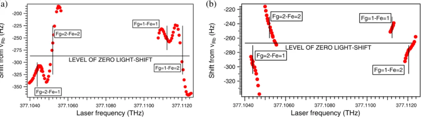
Figure 4. (a) Light-shift of the clock transition in the DR scheme, as a function of the laser frequency. (b) Corresponding data for the CPT
scheme. The total laser intensity is 0.2 µW cm−2for both schemes. Short vertical lines indicate the laser frequencies when stabilizing to the
atomic transitions used in figure 3.
the Fg= 1 or Fg= 2 ground state to either the Fe= 1 or
Fe= 2 excited state. In the CPT case, the laser carrier
frequency is stabilized to the same four transitions, each time using the carrier and one of the first-order sidebands for coupling the two ground states to one common excited state. The light-shift coefficientα is given by the slopes of the line fits in figures 3(a) and (b).
The shifts of the clock transition as a function of the laser frequency for the DR and CPT schemes are shown in figures 4(a) and (b), respectively. Here, the laser frequency is not stabilized to the reference transitions, but is set to different detunings and is measured with a high-resolution wavemeter. The light-shift coefficient β is given by the local slopes of the data and depends on both the laser detuning and the laser intensity.
Similar measurements have been reported in [7], but only for the DR case in a buffer gas cell and not over such a large laser frequency range. Theoretical results presented in [8] show some differences compared to our data (figure 4(a)). In particular, in our data for DR we find two laser frequencies that give a zero-value clock frequency shift, i.e. zero-intensity light-shift, but four such occurrences are given in [8]. It will be interesting to further study these differences and to analyse the analogous results for the CPT case.
4. Conclusions
We have measured the intensity and frequency light-shifts of the clock transition in a wall-coated Rb vapour cell using both the DR and the CPT schemes, in view of future Rb atomic clocks using wall-coated cells. When the laser frequency is stabilized to the Fg= 2 to Fe= 1 transition,
α coefficients are equal to −1.5 × 10⁻¹¹cm2µW−1 for the
DR scheme and −6 × 10⁻¹²cm2µW−1 for the CPT scheme.
For the laser frequencies around the same transition and at a laser intensity 0.2 µW cm−2, the β coefficients are equal to 80 and −93 mHz MHz−1 for the DR and CPT schemes, respectively. These results are of importance for understanding the medium- and long-term stability limits
of Rb atomic clocks using wall-coated cells and for the performance optimization of such clocks.
Acknowledgments
This work was funded by the Swiss National Science Foundation (project 200020-118062) and the European Space Agency. We also acknowledge support from the Association Suisse pour la Recherche Horlogère. We thank F Gruet, P Scherler and M Durrenberger (all at LTF) for help with the experiments.
References
[1] Barrat J and Cohen-Tannoudji C 1961 Etude du pompage optique dans le formalisme de la matrice densité J. Phys. Radium22 329–36
[2] Vanier J and Audoin C 1989 The Quantum Physics of Atomic Frequency Standards(Bristol: Adam Hilger)
[3] Affolderbach C, Droz F and Mileti G 2006 Experimental demonstration of a compact and high-performance laser-pumped rubidium gas-cell atomic frequency standard IEEE Trans. Instrum. Meas.55 429–35
[4] Breschi E, Kazakov G, Schori C, Di Domenico G, Mileti G, Litvinov A and Matisov B 2010 Study of light effects in the atomic-motion-induced Ramsey narrowing of dark resonances in wall coated cells Phys. Rev. A 82 063810 [5] Bandi T, Affolderbach C and Mileti G 2010 Study of Rb 0–0
hyperfine double-resonance transition in a wall-coated cell Proc. 24th European Frequency and Time Forum (Noordwijk, The Netherlands, 13–16 Apr. 2010)(Noordwijk: European Space Agency) p 117 (www.eftf.org)
[6] Affolderbach C and Mileti G 2005 A compact laser head with high-frequency stability for Rb atomic clocks and optical instrumentation Rev. Sci. Instrum. 76 073108
[7] Deng J Q, Mileti G, Lopez-Romero J M, Jennings D A, Walls F L and Drullinger R E 1997 Study of the frequency stability of laser-pumped rubidium gas-cell frequency standards Proc. 11th European Frequency and Time Forum (Neuchˆatel, Switzerland, 4–7 Mar. 1997)(Neuchâtel: Swiss Foundation for Research in Microtechnology) pp 211–5 (www.eftf.org)
[8] Mathur B S, Tang H and Happer W 1968 Light shifts in the alkali atoms Phys. Rev. 171 11–9