An Analysis of Possible Microbiologically Influenced Crevice
Corrosion of 316 Stainless Steel in a Seawater Environment
by
William R. N. Howell Jr. B.S. Biomedical Engineering
Tulane University (1984)
SUBMITTED TO THE DEPARTMENT OF OCEAN ENGINEERING IN PARTIAL FULFILLMENT OF THE REQUIREMENTS FOR THE DEGREE OF
MASTER OF SCIENCE IN OCEANOGRAPHIC ENGINEERING at the
MASSACHUSETTS INSTITUTE OF TECHNOLOGY and the
WOODS HOLE OCEANOGRAPHIC INSTITUTION SEPTEMBER 1996
C Massachusetts Institute of Technology 1996. All Rights Reserved.
A uthor: ... c .:... ... ... .../
Department of Ocean Engi ering, MIT and the MIT-WHOI Joint Program in Oceanographic Engineering, August 9,1996 Certified by:... ...
Koichi Masubuchi,Kawasaki Professor of Materials
Science and Ocean Engineering, MIT, Thesis Supervisor
Certified by: ... ... •...am... ...... ..
/
Albert J. Williams 3rd, Senior Scientist, Applied Ocean Physics and En g, WHOI, Thesis ReaderAccepted by:... ... ... . ...
Professor Hennril idt air, Joint Committee for Applied Ocean Sci and Engineering, MIT-WHOI
An Analysis of Possible Microbiologically Influenced Crevice
Corrosion of 316 Stainless Steel in a Seawater Environment
by
William R. N. Howell Jr.
Submitted to the Department of Ocean Engineering on August 9, 1996 in Partial Fulfillment of the Requirements for the Degree of Master of Science in
Oceanographic Engineering
ABSTRACT
An analysis was conducted of 316 Stainless Steel components which exhibited an unusual degree of crevice corrosion after exposure to seawater for approximately one year. After conducting research into the possible chemical and microbiological mechanisms for the corrosion, a
metallurgical and microscopic examination of the components was performed. Results of these examinations indicated that the corrosion observed was probably the result of an interaction between the Gallionella aerobic iron bacteria and the anaerobic sulfate reducing bacteria
Desulfovibrio and Desulfomaculum.
A laboratory crevice corrosion experiment, in accordance with the method of ASTM G78-89, was performed in an attempt to reproduce this rapid corrosion rate and test this hypothesis. However, the rapid corrosion experienced in the open ocean environment could not be
reproduced in the laboratory. The results obtained indicated a likely sensitivity to the presence of local pollutants, required for the rapid growth of the sulfate reducing bacteria. Finally, possible preventative measures and additional at-sea experiments were proposed.
Thesis Supervisor: Koichi Masubuchi
Acknowledgments
In response to a compliment on his discoveries, Sir Isaac Newton said: "If I have seen farther than other men, it is because I stood on the shoulders of giants." In completing this thesis and my Masters, I too have stood on the shoulders of others. This thesis could not have been completed without the help and guidance of Professor Koichi Masubuchi of MIT and Dr. Albert "Sandy" Williams of WHOI. Gentlemen, please accept my profoundest thanks; I shall try to put what you have each taught me to good use in my future endeavors.
I would like to thank my fellow graduate student Dave Walworth for all his assistance in teaching how to use the video and laser microscopes in the Welding Laboratory at MIT. Thanks also to LTJG Tom Singleton, for making me aware that this corrosion problem existed and could well serve as the basis of a thesis.
Lastly, my greatest thanks go to my family, my wife Elaine and daughter Liana. For helping me with everything from photographing specimens to purchasing 120-grit paper, you've both been there for me whenever I needed you. Your love and support have been what kept me going and made possible whatever I have accomplished.
Table of Contents
Abstract ... ... ... 2 Acknowledgments.. ... ... . .... ... .. ... 3 Table of Contents ... ... ... 4 L ist of F igures... .. .. .. ... ... ... 5 Chapter 1: Introduction ... . ... ... 6Chapter 2: Crevice Corrosion Chemical Mechanisms... 12
I. Chemical Mechanism of Crevice Corrosion ... ... 13
II. M ethods of Testing... ... ...16
III. Effects of Environmental Factors... ... ... ... 19
IV. Standard Actions to Prevent or Minimize Crevice Corrosion ... 23
V. Summary.. ... ... 25
Endnotes for Chaper 2...27
Chapter 3: Microbiologically Influenced Corrosion Mechanisms...29
1. In tro d u ctio n ... 2 9 II. Sulfate Reducing Bacteria... ... 30
III. Iron and M anganese Bacteria... .. ... ... ... 31
IV. Sulfur Oxidizing Bacteria... ... 33
V . Sum m ary... .. . .... ... ... 33
E ndnotes for C hapter 3... ... 34
Chapter 4: Analysis of Corrosion-Damaged Specimens...35
I. M etallurgical Analysis of the Base M etal... ... 35
II. Examination Using a Video Microscope... . ... ... 36
Ill. Sum m ary ... ... ... ... ... 38
Endnotes for Chapter 4...40
Chapter 5: Laboratory Crevice Corrosion Test...48
I. Procedure... .. ... ... ... .. ... ... ... 48
II. Experimental Results...49
III. Sum mary... . .. ... 50
C hapter 6: C onclusions... ... ... ... ... 58
1. Conclusions from Analysis... .... . ... 58
II. Recommendations For Prevention... ... ... ... 59
III. Recommendations for Additional Experimentation... ... 60
List of Figures
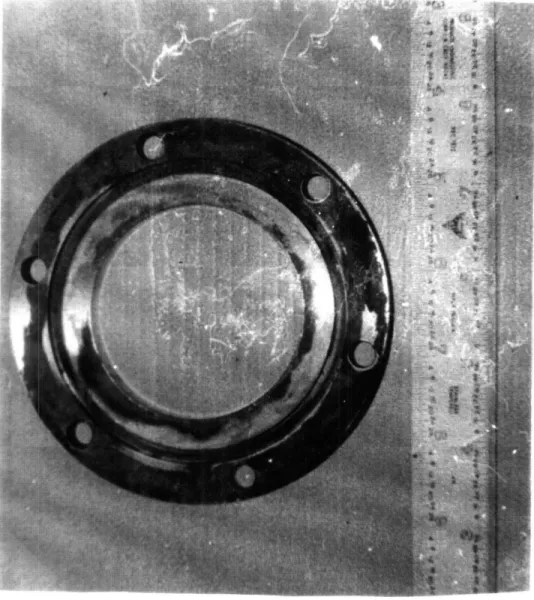
Figure 1-1: Corrosion-Damaged Specimen #1 (O-ring grooved side)...9
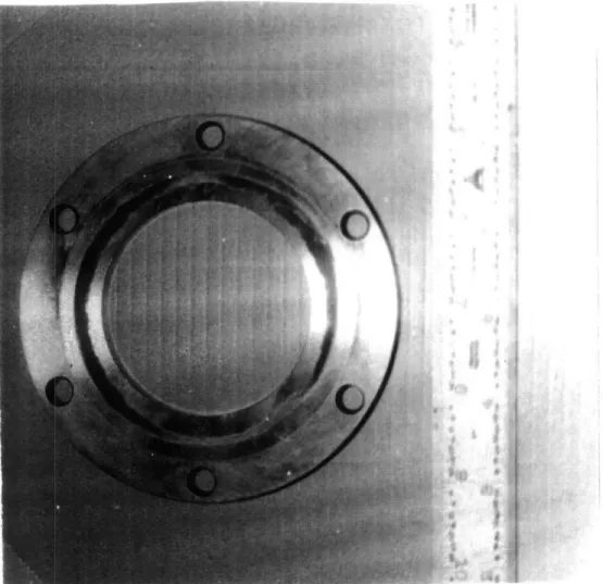
Figure 1-2: Corrosion-Damaged Specimen #1 (Reverse side)...10
Figure 1-3: Line Drawing of Vorticity Instrument within Support Pyramid... 11
Figure 4-1: Specimen #1 Cavernous Pit (20X magnification)...41
Figure 4-2: Specimen #1 Edge View of Deep Pit (20X magnification)...41
Figure 4-3: Specimen #1 Reverse Side (20X magnification)... ... 42
Figure 4-4: Specimen #2 Hemispherical Pits (20X magnification)... 42
Figure 4-5: Specimen #2 Reverse Side (20X magnification... 43
Figure 4-6: Specimen #1 Cavernous Pit (100X magnification)...43
Figure 4-7: Specimen #1 Deep Pits (100X magnification)... .... 44
Figure 4-8: Specimen #1 Deep Edge Pit (100X magnification)... 44
Figure 4-9: Specimen #1 Deep Edge Pit (100X magnification)... 45
Figure 4-10: Specimen #2 Hemispherical Pits (20X magnification)... 45
Figure 4-11: Specimen #2 Hemispherical Pits (20X magnification)... 46
Figure 4-12: Specimen #1 Hemispherical Pits (20X magnification)...46
Figure 4-13: Specimen #2 Deep Pits (100X magnification)... .... 47
Figure 4-14: Specimen #2 Deep Pits (100X magnification)...47
Figure 5-1: Sterile Seawater Specimen (20X magnification)... ... 52
Figure 5-2: Sterile Seawater Specimen (20X magnification)... 52
Figure 5-3: Active Seawater Specimen (20X magnification)...53
Figure 5-4: Active Seawater Specimen (20X magnification)... 53
Figure 5-5: Active Seawater Specimen (100X magnification)...54
Figure 5-6: Active Seawater Specimen (100X magnification)...54
Figure 5-7: Active Seawater Pit (60X magnification)... ... 55
Figure 5-8 Active Seawater Pit (100X magnification)... ... 55
Figure 5-9: Active Seawater Specimen (600X laserscope magnification).. ... 56
Figure 5-10: Active Seawater Specimen (600X laserscope magnification)...56
Figure 5-1 1: Active Seawater Pit (600X laserscope magnification)... 57
CHAPTER 1: Introduction
One of the most useful methods for studying the behavior of the ocean is the long-term deployment of in situ instrumentation to measure various parameter of interest, such as
temperature, salinity, velocity, or vorticity. Whether fixed or free-floating, these instruments can record large amounts of data and relay it upon their eventual recovery. Obviously, to be
successful in this task, this instrumentation must be able to withstand the rigors of exposure to the ocean environment throughout its expected at-sea life. Premature failure, such as that caused
by an unexpectedly rapid corrosive attack, can cause the loss of many man-hours and ship-time, not to mention the waste of scarce funding.
I. THE PROBLEM
Recently, some 316 Stainless Steel instrumentation deployed by scientists from the Wood Hole Oceanographic Institution has suffered unexpectedly rapid crevice corrosion, causing the loss or near loss of the experiments. The occurrence of this accelerated corrosive attack has been intermittent, but it has been noted on several different experiments. This rapid corrosive attack is unusual and significant; 316 Stainless Steel is the standard commercial material of choice for seawater applications in which pitting or crevice corrosion is of concern. Specifically, this alloy contains molybdenum to reduce its susceptibility to these types of localized corrosion. The failure of this alloy to perform as expected raises serious problems for the long-term deployment of ocean instrumentation.
experiment which exhibited this rapid and severe crevice corrosion. These components were 316 Stainless Steel space rings which were used to join two pressure housings on a large fixed instrument. The components were produced on an end-mill in the machine shop at the Woods Hole Oceanographic Institution and given a smooth surface finish. Each has six holes through which fasteners passed and an O-ring groove milled into one side. Outer diameter is 4.5 inches, inner diameter is 3.5 inches, and thickness is 3/8 inches. Figures 1-1 and 1-2 are photographs of one of these corrosion-damaged components, while figure 1-3 is a line drawing of the vorticity instrument suspended within its tripodal frame for deployment on the sea bottom. The location of the two rings in the pressure housing is indicated by the arrow. The rings were separated from the rest of the instrument by spacers composed of Delren plastic.
The particular components which were analyzed by me were utilized in an instrument deployed on 11 July 1994 at 480 23.55' N latitude 1240 31.91' W longitude in 130 meters of water off the coast of the state of Washington. Surface tidal currents were approximately 3 knots. A sacrificial zinc was attached in the immediate vicinity of the spacer rings. When the instrument was recovered on 28 May 1995, it was immediately noted that the zinc had been totally
consumed. Upon disassembly, the severe corrosion (see figs. 1-1 and 1-2) of the rings was noted, as well as the fact that they were both heavily coated with a brown slime. At the time, it was assessed that if the corrosion had proceeded much further, the pressure boundary would have been breeched, the experiment flooded out, and its data lost.
II. THE COURSE OF ACTION
In an attempt to understand and possibly prevent the future occurrence of this type of 7
rapid crevice corrosion, I have conducted an analysis of this particular corrosion event. First, I conducted research into the possible mechanisms, both chemical and microbiological, which could support crevice corrosion. Next, I examined the two damaged components in an attempt to glean as much data as possible to support the formulation of an explanatory hypothesis. Then I attempted to reproduce the corrosion in a laboratory setting to test my hypothesis. Finally, I have attempted to synthesize a conclusion utilizing all the available data and to formulate
recommendations for both prevention and further research.
Unfortunately, in the course of my analysis I was limited by several factors. First, the corrosion-damaged specimens I obtained had been cleaned; this precluded a direct examination of the composition of the brown slime. Second, I could not allow my corrosion experiment to continue for nearly a year as took place in the actual instance of corrosion, but was forced to limit
it to two months. Finally, the environment of my corrosive experiments could not exactly duplicate the ocean environment where the original corrosion occurred. However, within these limitations, I believe my analysis has produced some useful results.
Figure 1-1: Corrosion-Damaged Specimen # (O-ring grooved side)
( i 9 1 ad~ r ;~ 51 h
Figure 1-3: Line Drawing of Vorticity Instrument within Support Pyramid 11
Chapter 2: Crevice Corrosion Chemical Mechanisms
The excellent resistance of stainless steels to general corrosion has made them frequently the material of choice for design applications involving exposure to seawater. The presence of approximately 19,000 ppm Cl" and other impurities, coupled with possible fouling by organisms present in natural seawater, make for a quite hostile corrosive environment. When operating under oxidizing conditions, the passive behavior of stainless steels would seem to be an ideal solution to the problems presented by a seawater environment. However, the same passive behavior which makes stainless steels very resistant to general corrosion renders them
susceptible to various types of localized corrosion. Localized corrosive attack constitutes a much more difficult engineering problem due to its rapid and unpredictable nature. In this chapter I will present an overview of current research dealing with one of these types of localized attack, crevice corrosion in the seawater environment.
The nature of mechanical design and fabrication makes the elimination of crevice sites extremely difficult. Pieces of equipment must often be joined together with fasteners, fitted together with flanges, or have occluded or low flow regions produced by other over-riding design constraints. The all-pervasive nature of crevices has made crevice corrosion a tremendous concern in stainless steel seawater applications, especially since it usually attacks the mechanical joints of engineering structures. While the mechanism for crevice corrosion is believed to be
similar to that of pitting corrosion, the pre-existence of the crevice site makes this type of localized attack even more difficult to predict and prevent.
the mechanism of crevice corrosion, the laboratory methods used to test materials for susceptibility to crevice corrosion, environmental variables effecting crevice corrosion
performance in actual materials, and suggested methods to prevent or minimize crevice corrosion of stainless steels exposed to seawater.
I. CHEMICAL MECHANISM OF CREVICE CORROSION
Crevice corrosion is a form of localized corrosion which occurs within crevices or occluded regions where a stagnant solution is present. The geometry of the crevice is critical, since to function as a site the crevice must be sufficiently wide to permit electrolyte entry, but also sufficiently narrow to ensure transport in and out of the crevice is restricted. A typical crevice width would be on the order of a micron; later in this chapter I will survey the work of R. M. Kain, who conducted laboratory testing on the effect of crevice width versus depth for various alloys.'
Initially, the metal is assumed to have formed a passive layer over its entire surface, including the surface within the crevice. However, the cathodic reaction occurring in the crevice
( most probably the reduction of 02 + 2H20 to 40H- ) rapidly depletes the oxygen concentration,
which cannot be replaced due to transport restrictions. The anodic oxidation of the metal
continues, releasing positively charged metal ions into the crevice, which attract Cl" ions into the crevice. The resulting metal chloride is hydrolyzed by water to produce hydroxide and free acid,
M+CI + H20 - MOH +
H+CI-causing a rapid decrease in pH to values below 2 within the crevice, though the bulk solution remains neutral. Once this highly acidic pH is established, passive film breakdown occurs,
followed by a rapid form of corrosion, similar to the autocatalytic reaction which occurs in pitting.2
An interesting sidelight in this process is the effect of chromium. Chromium is the essential alloying element for the production stainless steel, as it is chromium oxides which form the protective passive layer. However, the acidification within the crevice is probably
dominated by the hydrolysis of chromic ions,
Cr + + 3H20 - Cr(OH)3 + 3H+.
When the chemistry within the pits was analyzed, only trace amounts of ferric(Fe3') ions were found, and nickel ions do not hydrolyze to yield pH values below neutral. Pure chromium also exhibits the same crevice pH as stainless steels, which supports this assessment.3 Therefore, an increase in chromium content, while increasing the resistance of stainless steels to the initiation of attack, also increases the severity of crevice corrosion, once initiated, by increasing the acidification of the environment within the crevice. For a typical specimen of 316 SS in a 0.1 micron wide by 0.3 micron deep crevice, a pH as low as 1.1 has been measured.4
Nickel, the next most common alloying element for stainless steel, is esselLially neutral in its effect on crevice corrosion, though its addition does raise the pitting potential of an alloy. Since the hydrolysis of Ni2> yields a neutral pH, its presence will not contribute to the
acidification within the crevice.
Another critical factor influencing the mechanism of crevice corrosion is the presence of molybdenum. Numerous tests demonstrate that for both austenitic and ferritic stainless steels, molybdenum provides the greatest improvement in crevice corrosion resistance. For example:
# of Attacked Sites Penetration Range(mm)
Side 1 Side 2 Side 1 Side 2
AISI 304 20 2 021 to 0.97 0.25, 0.29 0 18 none 0.31 to 1.40 18 4 0.14 to 1.35 0.10 to 0.17 AISI 316 11 2 0.51 to 1.89 0.54, 0.61 6 11 0.26 to 1.43 0.23 to 0.78 9 10 0.33 10 1.63 0.50 to 0.93
Results of 28 Day Multiple Crevice Testing in Seawater at 35 C5
AISI 316, with 2.5% wt Mo, had fewer sites attacked than 304, which has no Mo. For austenitic stainless steels, a molybdenum addition as low as 2 to 4% can produce a significant improvement in crevice corrosion resistance in seawater6 Molybdenum, like nickel and chromium, raises the
pitting potential of the alloy. This suggests that it increases the difficulty of breaking down the passive film. Additionally, it has been suggested that a molybdenum salt film may form within the crevice and inhibit the propagation of crevice attack. Also, in alloys with >5% molybdenum, a protective salt film stabilized by molybdate may precipitate. 7
An additional alloying element which effects resistance to crevice corrosion in austenitic stainless steels is nitrogen. Unlike its effect on ferritic stainless steel, a nitrogen level of around 0.20% was found to have a very favorable effect on resistance to crevice corrosion in austenitic and duplex stainless steels, in addition to helping retard sigma-phase formation.8
As for the effects of other alloying elements other than chromium, nickel, molybdenum, and nitrogen, silicon and copper, when present with molybdenum in austenitic stainless steels, have a beneficial effect on crevice corrosion resistance in seawater. No effect was found for columbium and titanium on crevice corrosion in seawater tests, while small additions of palladium and rhodium were detrimental.9
Several attempt have been made to quantify the effects of these alloying elements upon the pitting and crevice corrosion resistance of the resulting alloy, and it is now common to see a pitting resistance equivalent (PRE) referred to in the literature:
PRE=CR wt% + (3.3xMo wt%) +(16 to 30xN wt%)
The contribution of nitrogen is only applicable to austenitic and duplex stainless steels. This formula permits a quantitative comparison of the relative crevice corrosion resistances of two different alloys.'"
To summarize the effects of alloying elements on crevice corrosion: Ideally, to minimize crevice corrosion attacks in seawater, stainless steels should contain at least 25% Cr and 3.5% Mo. In addition, austenitic and duplex stainless steels require a high nitrogen level of around 0.20%. Reducing the chromium content to 18-20% requires increasing Mo to at least 6% to maintain good crevice corrosion resistance."
II. METHODS OF TESTING
The ASTM has promulgated two standard methods of testing the crevice corrosion susceptibility of materials. ASTM G48 tests samples in FeCl3 solutions, while ASTM G78
methods, the results obtained by G78 are more typical of those seen in actual service and are most easily interpreted.
In ASTM G48, polytetrafluoroethylene (PTFE) blocks are held in place on both sides of a sheet specimen using rubber bands. The test assembly is then immersed in a FeC13 solution at a
known temperature for a fixed period of time. The susceptibility to attack is evaluated by measuring the depth of the attack at the crevices under the PTFE blocks and under the rubber bands.12
In ASTM G78, the PTFE blocks of G48 are replaced nonmetallic crevice formers of acrylic plastic, nylon, polyethylene, PTFE, or acetal resin. These crevice formers are pre-cut to produce the crevice geometry of interest. Two crevice formers are held in place on either side of a sheet specimen by a fastener through the center of all three. The control of the torque of that fastener, and by extension the control of crevice width, is much more precise than the rubber band tension in G48, leading to more uniform results. For example, on a specimen of AISI 304 stainless steel in 25 C seawater, a torque of 8.5Nm (75 in-lbs) on an acetal resin crevice former will routinely result in a crevice of <0.05 microns and crevice corrosion within 30 days. The specimen assemblies are then submerged in seawater for the desired time period, though a minimum exposure of 30 days is recommended. Susceptibility is evaluated in much the same way as in G48, by measuring the number of crevice corrosion sites beneath the crevice former and the maximum penetration at each site. Total mass loss can also be measured. This test is useful since it allows for the relative ranking of the typical crevice corrosion resistance of various alloys under nominal conditions. 13 The results of a G78 test on a sample of the 316 SS used to
construct the WHOI device will be reported later in this thesis. 17
In addition to the immersion tests discussed above, two other laboratory test of crevice corrosion were used by Lee, Kain, and Oldfield in their article "The Effect of Environmental Variables on Crevice Corrosion of Stainless Steels in Seawater". One method utilized a remote crevice assembly, in which a physically separated but electrically connected pair of specimens is used. The smaller of the two specimens is sandwiched between two acrylic plates which create the crevice. Both the small crevice anode specimen and the large, crevice cathode specimen are exposed in the environment of interest. The measurement of current between these two
specimens provides an indication of time to initiation of crevice corrosion as reflected by the rapid increase in current. It also allows for measurement of the rate of propagation of corrosion
in the crevice as indicated by the magnitude of the current. The corrosion potential of the specimen can also be monitored as well as measurement of mass loss and depth of attack on the anode specimen at the conclusion of the test.14
The second method used by Lee, Kain, and Oldfield was a compartmentalized cell. This method is similar to the remote crevice assembly discussed above, with two specimens which are physically separated but electrically connected; however, in this test, the two specimens are exposed in separate environmental compartments which are connected by an
electrically/ionically conductive bridge. The large cathode specimen is exposed in one
compartment containing the bulk environment of interest. The small anode specimen does not have a physical crevice; rather it is exposed in a deaerated acid-chloride solution. The
composition of this acid-chloride solution can be varied to simulate any crevice environmental conditions desired, such as those predicted to develop by a mathematical model."
corrosion in welded stainless steels. Two ring shaped test specimens with inner and outer diameters of 9 and 20 mm respectively were mounted in plane contact with each other. Total crevice area was 5 cm2. Each pair of specimens consisted of one specimen of base material and one including a weld. The specimens were mounted in a nylon holder and slowly flowing natural seawater from a 60 m depth was used as the electrolyte with continuous replacement. Temperatures were held constant at 9 + 2 C and 30 + 2 C. The potential was varied with a potentiostat; and the initiation potential, corrosion rate after initiation, and the repassivation potential were measured. 6
These various methods for studying and measuring the initiation and rate of crevice corrosion attack in the laboratory elaborate two points. First, there is no totally satisfactory method of determining material susceptibility to crevice corrosion; each of the methods outlined above have different advantages and disadvantages. Second, no laboratory testing method yet devised is particularly effective at predicting specific crevice corrosion in actual materials exposed to a natural seawater environment. As will be discussed in the next section, the interplay of numerous environmental factors influencing crevice corrosion initiation and propagation make translating these laboratory results into engineering predictions much more problematical. "
III. EFFECTS OF ENVIRONMENTAL FACTORS
Numerous environmental factors have very significant effects on the initiation and propagation of crevice corrosion in a seawater environment. Several of the articles I reviewed
for this chapter dealt with attempts to analyze and quantify the effects of some of these factors. In this section, the factors I will discuss are crevice geometry, Cl- concentration, seawater temperature, solution velocity, and natural versus artificial seawater.
Obviously, in order to have crevice corrosion, you must have a crevice. However, the depth versus width required to initiate crevice corrosion vary with the material being tested, and the severity of attack on a given specimen is also effected. Indeed, it has been suggested that the wide data scatter seen in various crevice corrosion studies arises primarily from an inability to accurately reproduce the geometry of a tight crevice.'" One mathematical model predicts that a difference in the crevice gap of 0.01 microns could be the determining factor for controlling the occurrence of crevice corrosion.19 This model predicts that the maximum crevice gap in an
ASTM G78 type test of AISI 316 for which corrosion would occur is 0.02 microns, while less resistant AISI 304 would exhibit crevice corrosion with gaps up to 0.05 microns. Essentially, the tighter the crevice, the more stagnant and hostile the environment produced, and therefore the more likely the initiation and the more aggressive the propagation of the corrosion. Crevice depth required for corrosion is directly proportional to crevice width; deeper crevices are
required for initiation to occur with widening gaps. This implies that for laboratory tests having a fixed crevice depth, such as G78, reproducibility of results will be highly dependent on the reproducibility of the crevice gap tightness at each site. 20 Increasing depth and decreasing gap are detrimental, therefore crevices should be kept as open and shallow as possible.
Since the presence of chloride ions is essential for the breakdown of the passive film on stainless steel and are major players in the autocatalytic pitting process, it is hardly surprising that higher concentrations make for more severe crevice corrosion. At Cl- concentrations less
than those present in seawater, crevice corrosion initiation requires smaller gaps to achieve the concentrations necessary to initiate crevice corrosion. Also of interest, the difference in
susceptibility, as measured by required gap width, between AISI 304 and 316 is reduced at lower Cl- concentrations. In 1000 mg/L Cl-, the difference in required gap size is an order of
magnitude less than the difference in 20,000 mg/L Cl- water (seawater concentration).2'
Seawater temperature can also affect the crevice corrosion process. In natural seawater, the effect of increasing temperature in the ambient range is to increase the extent of crevice
corrosion. The effect of increasing temperature beyond the ambient range, however, is to decrease the extent of propagation of crevice corrosion. Tests of 304 and 316 SS show
penetration ranges one to two orders of magnitude less at 50 C compared to identical tests at 28 C.22 The exact mechanism for this observed phenomenon is not clear. Conventional
electrochemical tests in natural seawater yield data which traditionally would imply that increased temperature should increase the extent of crevice corrosion. Some reported results showed that as the seawater temperature is increased, there is an observed shift in both pitting and protection potentials to more active values and there is an increase in the hysteresis on polarization curves.23 The key to this phenomenon would seem to be in the kinetics of the
oxygen reduction reaction, and it has been suggested that the effect results from a correlation among temperature, oxygen reduction rate, and aerobic bacteria settlement on the areas adjacent to the crevice.24
Velocity is a particularly important parameter in seawater systems because low design velocities can allow the settlement of debris or fouling organisms which form crevice sites. Conversely, high velocities could be expected to remove some crevice formers from the system
and flush other crevices to such an extent that the aggressive acid-chloride solution may not form. The solution velocity could also be expected to influence the reactions occurring at cathodic surfaces which are sustaining the active crevice corrosion at local anodes, most
particularly the reduction of oxygen. Lee, Kain, and Oldfield, using the remote crevice assembly discussed in section III, were able to calculate the critical anode to cathode relationships required to maintain the crevice corrosion reaction under anodic control. Mathematical models predicted a critical ratio of 9:1 in stirred seawater and 35:1 in quiet seawater; measured critical ratios were <20:1 in stirred and between 20:1 and 100:1 in quiet seawater.25 Below their respective critical
ratios, where both corrosion reactions are under cathodic control, velocity has minimal effect. Above the critical ratio, where both reactions are under anodic control, velocity again has a minimal effect. Therefore, the most significant effect of velocity is to lower the critical cathode to anode ratio for the shift from cathodic to anodic control.
In addition to the level of chloride, the nature of the chloride-containing solution is quite important in the crevice corrosion process. Here is tabular comparison of the crevice corrosion behavior in natural seawater with that in ASTM synthetic seawater:26
Synthetic Seawater Natural Seawater Temperature %Sites attacked Max depth %Sites attacked Max depth
( C )
(mm)
(mm)
304 SS 25 31 0.11 42 2.91
316 SS 25 38 0.08 4 1.12
304 SS 50 31 0.15 33 0.18
316 SS 50 28 0.13 38 0.08
The results are from a standard ASTM G78 multiple crevice assembly test. As can be seen, both alloys suffered an order of magnitude greater penetration in the natural seawater than in the synthetic seawater at ambient temperatures. Similar results are obtained using the remote crevice assembly; measured corrosion currents indicate a propagation rate for crevice corrosion of 316 SS in natural seawater which is 10 to 20 times that of 316 in synthetic seawater. Tests using the compartmentalized cell suggest that the difference is controlled more by reactions at the cathode surface than by the corrosion reactions occurring at the anode. Anodic processes may control reaction rates in natural seawater with no limits imposed by cathodic reactions. In synthetic seawater, however, oxygen reduction may be a rate controlling factor.27 A final consideration in
the comparison of synthetic and natural seawater is the impact of biological factors; I will discuss the influence of these factors in detail in the next chapter.
Environmental conditions, together with a number of interrelated metallurgical and geometrical factors, can greatly impact both the initiation and subsequent propagation of crevice corrosion. Crevice geometry, Cl- concentration, temperature, velocity, oxygen reduction and biological activity as they relate to area ratio considerations all have very important effects on the crevice corrosion process. Given the tremendous difference in the corrosion propagation rate between them, it would also seem critical to forego the convenience of using synthetic seawater for the much more aggressive natural variety.
IV. STANDARD ACTIONS TO PREVENT OR MINIMIZE CREVICE CORROSION
There are many actions which can be taken during the design process to avoid or 23
minimize crevice corrosion. The most obvious step would be to eliminate crevices all together; however, this is seldom practicable in a real-world design. Welded joints, properly designed and constructed to eliminate crevices, are preferable to bolted or riveted joints. Those crevices which must exist should be kept as wide and shallow as possible; as discussed above, the deep, narrow crevice produces the most aggressive environment. Gaskets should be properly sized to
minimize crevices exposed to seawater. If possible, metal/nonmetal joints should be avoided, as these are usually tighter than metal/metal joints.28 Operating temperatures are also of interest;
temperatures in the vicinity of 50 C cause a 10 to 20 times reduction in crevice penetration rate from that at ambient. Once the possibilities of designing away crevices has been exhausted, it is time to move on to material selection.
Choice of the appropriate material for components likely to experience crevice conditions is critical to successful design. From a metallurgical viewpoint, sufficiently high levels of
chromium and molybdenum are essential. If expense does not preclude its use, a alloy of at least
25% Cr and 3.5% Mo will be highly resistant to crevice corrosion attack. If such a high quality material cannot be used, the available material with the highest pitting resistance equivalent (PRE) should be employed. If the entire component cannot be fabricated from highly resistant material, it may be possible to overlay the susceptible surfaces with a more crevice corrosion resistant alloy. Additionally, ASTM G78 provides a standardized procedure for obtaining relative susceptibility to crevice corrosion, though the criticality of crevice gaps makes reproducibility difficult. Another possible solution would be to replace the stainless steel component with a less-resistant carbon steel component. If the component can be designed for easy replacement, a carbon steel part corroding at a high but predictable rate may well be
preferable to a passive stainless steel that fails rapidly and unpredictably by crevice corrosion.29 Once the most crevice corrosion resistant material available has been selected, other steps can be taken. The surrounding cathodic surfaces near the crevice could be painted to prevent the
cathode to anode ratio from exceeding the critical ratio ( approximately 20:1, depending on flow conditions) required to put the crevice reaction under anodic control. This would significantly slow the rate of penetration. Increasing flow velocity could either improve or worsen out corrosion problems; it could eliminate stagnation in some crevices, but also reduces the critical cathode to anode ratio. Cathodic protection of the susceptible components can also be effective, though this technique is only practical for austenitic stainless steels, since hydrogen blistering occurs if cathodic protection is attempted for martensitic or ferritic stainless steels.3" Only crevices to a certain depth can be cathodically protected for any given material, but it has been shown that crevice corrosion in seawater at crevices formed by type 304 O-ring seals can be reduced by cathodic protection.3"
V. SUMMARY
Crevice corrosion of stainless steels is a troublesome localized attack occurring in stagnant and occluded regions. Due to its aggressive nature and the difficulty in removing all crevices and low flow regions from a design, it is a very serious problem. The mechanism for crevice corrosion is believed to be very similar to that of pitting corrosion, i.e. stagnant solution in the crevice becomes oxygen depleted, leading to a migration of Cl- ions into the pit to maintain charge neutrality, causing passive film breakdown and an autocatalytic reaction in an acid-chloride environment within the crevice. Various alloying elements can enhance the ability of
stainless steels to withstand this attack. Several standard and not so standard laboratory tests exist for determining the relative susceptibility of alloys to crevice corrosion, though
reproducibility of results is difficult for all current tests. Various environmental factors such as crevice geometry, chloride concentration, flow velocity, temperature, and biologic activity all interact at any given potential crevice site, making prediction of probability of initiation and rate of propagation extremely difficult. However, some basic engineering design principles can be applied to minimize the damage caused by this serious form of localized attack.
Endnotes for Chapter 2
1 .Kain, R. M., "Crevice corrosion behavior of stainless steel in seawater and related environments",CORROSION, Vol. 40, June 1984, p.317.
2.Sedricks, A. John, Corrosion of Stainless Steels, (New York, John Wiley and Sons, Inc) p 89. 3.Peterson, M. H., Lennox, T.J., and Groover, R.E., Material Protection, p. 23, January 1970.
4.Lee, T. S., Kain, R. M., and Oldfield, J. W., "The effect of environmental variables on crevice corrosion of stainless steels in seawater", MATERIALS PERFORMANCE, vol. 23, July 1984, p. 10.
5.Kain, p.316. 6.Sedricks, p. 101.
7.Sedricks, p. 103
8.Tither, G., "New developments in stainless steels for resistance to corrosion in seawater", Corrosion in Seawater Systems, (New York, Ellis Horwood) p. 15.
9.Sedricks, p. 103. 10O.Tither, p. 12.
1 1.Tither, p.23.
12.Standard Method G48-76, Annual Book ofASTM Standards, Vol. 3.02, ASTM, Philadelphia, p. 209, 1988. 13.Standard Method G78-89, Annual Book ofASTM Standards, Vol. 3.02, ASTM, Philadelphia, p. 329, 1994. 14.Lee, et al., p.9
15.Lee, et al., p. 10.
16.Rogne, Trond; Drugli, John M.; and Johnsen, Roy. "Testing for initiation of the crevice corrosion of welded stainless steels in natural seawater", MATERIALS PERFORMANCE, Vol. 26, September 1987, p.2 9.
17.Bond, A. P., and Dundas, H.J.,"Resistance of stainless steels to crevice corrosion in seawater",MATERIALS PERFORMANCE, vol. 23, July 1984, p.4 3.
18.Sedricks, p.96. 19.Kain, p. 315.
20.Kain, p.317. 21.Kain, p. 318. 22.Lee, et al., p.13.
23.Kain, R.M., "Localized Corrosion Behavior in Natural Seawater, A Comparison of Electrochemical and Crevice Testing of Stainless Steel," CORROSION/80, preprint No. 74 (1980).
24.Mollica, A.;Trevis, A.; Traverso, E.;"Crevice corrosion resistance of stainless steels in natural seawater in the temperature range of 25 to 40C", CORROSION, vol. 44, April 1988, p. 19 8.
25.Lee, et al., p. 14. 26.Lee, et al. P.12.
27.Lee, e al., p. 13. 28.Sedricks, p.108.
29.Jones, Denny A., Principles and Prevention of Corrosion, (Englewood Cliffs, NJ: Prentice-Hall, Inc., 1992), p.535.
30.Sedricks, p.105. 31.Peterson, et al., p.23.
Chapter 3: Microbiologically Influenced Corrosion Mechanisms
I. INTRODUCTION
In the previous chapter, I discussed the various chemical mechanisms for the crevice corrosion of stainless steels in seawater. In this chapter, I will discuss the possible mechanisms for microbiologically influenced corrosion (MIC) to occur and contribute to the instance of crevice corrosion of 316 Stainless Steel being studied in this thesis.
MIC does not represent a new form of corrosion; it is only the influence of living
organisms on the electrochemical reactions discussed in the previous chapter. In its most simple case, microbial activity does nothing more than create the localized geometry required to produce a crevice. In this particular case, since the crevice is already in existence, it is also possible that the microbes contribute to the formation of a concentration cell by consuming various chemical species within the crevice. Also, microbes produce metabolites such as organic or mineral acids, ammonia, or hydrogen sulfide which are corrosive to stainless steels. A number of microbes can concentrate halides which results in severe, localized corrosion of stainless steels. In still other cases, microbial activity interferes with the cathodic half-reaction under oxygen-free conditions resulting in increased anodic dissolution. Other ways that microbes can influence corrosion are oxidation of metal anions to less soluble forms (e.g., Fe"2 to Fe 3 by iron oxidizing bacteria),
destruction of protective coatings, and metabolism of inhibitors.' Each of the three major contributors to MIC are discussed below.
II. SULFATE REDUCING BACTERIA
Desulfovibrio and Desulfomaculum are the major sulfate reducing bacteria and are considered to be the most widely distributed and important organism associated with corrosion. They reduce sulfate to sulfide and are strictly anaerobic although they are capable of survival in aerated water. A high iron content is generally associated with their cell structure and wastes.
Their metabolism generally results in locally alkaline conditions. Their survival depends on the presence of oxygen scavengers to achieve anaerobic conditions. These rod-shaped bacteria
attack cast-iron, carbon and low alloy steels, and stainless steels, and contribute to the corrosion of high nickel alloys and copper alloys as well. Black FeS films in the center of conical pits generally characterize their attack on stainless steels. Bright and shiny surfaces are normally found at the active corrosion front. Rings of different color generally surround the pits.2
In 1934 von Wolzogen Kuhr and van der Vluget first theorized that the corrosion of iron buried in anaerobic soil was due to the activity of these bacteria.3 The half-cell reactions which they proposed are:
anodic reaction: 4Fe -4Fe+2 + 8e" electrolytic dissolution of water:
8H1120 - 8H+ + 80H-cathodic reaction:
8H+ + 8e" - 8H
cathodic depolarization (by bacteria): S04-2 + 8H - S-2 + 4H20
corrosion product: Fe+2 + S-2 - FeS
corrosion product: 3Fe'2 + 60H- - 3Fe(OH)2
Combined, these half-cell reactions produce the following overall reaction: 4Fe + S04-2 + 4H20 - 3Fe(OH)2 + FeS +
20H-The processes noted above apply to ferrous materials, particularly, the steels and cast irons. Sulfate reducing bacteria also contribute to the corrosion of stainless steels which rely upon the formation of Cr203 for protection. For stainless steel, involvement of these bacteria
results in open pits filled with black iron sulfide.
III. IRON AND MANGANESE BACTERIA
Pseudomonas are aerobic slime formers, generally found in corrosion deposits as relatively thin, uniform films. Their main contribution to the corrosion processes is to scavenge oxygen and harbor other species such as the sulfate reducing bacteria. They reduce Fe'3 to Fe42
and in so doing may expose active metal and thereby increase corrosion.4
Gallionella are aerobic iron bacteria that exude hydrated oxide. Their waste are high in iron and manganese and they can concentrate chloride. Their presence in MIC is typically manifested by the pitting of carbon and stainless steels. Pits in stainless steels generally exhibit very small entry and exit holes that open to a large corroded area. Corrosion deposits are hemispherical on carbon steels and low conical shapes on horizontally oriented stainless steel; rusty streaks on vertical surfaces. The bacterium itself is kidney-shaped.
Crenothrix, Leptothrix, Clonothrix, and Sphaerotilus are aerobic, filamentous bacteria that can corrode carbon and stainless steels. Their main metabolic effect is to oxidize soluble Fe to insoluble Fe(OH)3. They also concentrate and oxidize manganese. These bacteria generally
form low, hemispherical tubercles on carbon steel with oxygen depleted conditions beneath the tubercle. Deposits are typically brown or reddish brown.
Iron oxidizing bacteria oxidize the soluble ferrous ion to the less soluble ferric state as their primary energy source leading to the deposition of ferric hydrate and the creation of creviced geometries under tubercules comprised of the metal hydrate and the bacterial
exopolymer. Many of these species also tend to concentrate chloride and manganese as well as leading to high local concentrations of chloride in oxygen deficient areas, which is a prime contributor to devastating pitting and crevice corrosion of stainless steels. The influence of the iron oxidizing bacteria can be two-fold. First, the aerobic bacteria colonize the crevice and the oxygen concentration is depleted such that a differential aeration cell is produced. Localized corrosion may then proceed at the locally anodic region within the crevice. Secondly, as Fe÷2 is
oxidized to the less soluble Fe"3, the electrochemical potential at the surface is shifted in the
noble direction such that the pitting potential is exceeded and rapid corrosion is initiated. The oxidizing bacteria may further assist in this autocatalytic process by oxidizing the ferrous ions to the ferric state, thus keeping the potential in the pitting regime. The pits induced on stainless steel as influenced by Gallionella frequently have very small entry and exit holes with large subsurface cavities, which is also consistent with the 316 SS samples being studied in this thesis.5
IV. SULFUR OXIDIZING BACTERIA
Thiobacillus and Ferrobacillus are aerobic and autotrophic. Thiobacillus oxidizes sulfide to sulfate and forms H2SO4; some species can generate a pH < 1. They also oxidize ferrous ions
to the ferric state. They often coexist with sulfate reducing bacteria. Brown deposits of ferric sulphate are often noted in waters containing these organisms.
Thiothrix and Beggiatoa are rod-shaped, aerobic bacteria that oxidize H2S to elemental
sulfur. The result of their involvement in a corrosion reaction is often characterized by a yellow sulfur deposit. Their major contribution to the corrosion process is to form a slime in which sulfate reducing bacteria may thrive.
Microbes such as Thiobacillus, Ferrobacillus, Thiothrix, and Beggiatoa oxidize sulfur and sulfur compounds under aerobic conditions. Sulfuric acid produced in their metabolic process is a potential source of metallic corrosion although one that is infrequently reported.6
V. SUMMARY
It is possible that any or all of the three types of MIC discussed in this chapter are involved in the crevice corrosion being studied. Metalurgical analysis of the samples and laboratory corrosion testing (reported in following chapters) will be required to narrow the field of possibilities. However, the small entry holes and large corroded regions coupled with the slime reported on the recovered samples strongly suggests some MIC involvement.
Endnote for Chapter 3
1.Licinia, George J. Sourcebook For Microbiologically Influenced Corrosion in Nuclear Power Plants. Electric Power Research Institute NP-5580, 1988, p.2-2.
2.ibid, p. 2-4.
3.C.A.H. von Wolzogen Kuhr and L.W. van der Vlugt, Water 18, 1934, p. 147.
4.D.H. Pope, D.J. Duquette, A.H. Johannes, P.C. Wayner, "Microbially Influenced Corrosion of Industrial Alloys", Materials Performance, April 1984.
5.Licinia, p. 2-8. 6.ibid, p.2-9.
Chapter 4: Analysis of Corrosion-Damaged Specimens
As discussed in chapter one, I obtained two specimens of severely crevice corrosion damaged 316 stainless steel from a vorticity-measuring instrument which had been in-place in the open ocean for approximately twelve months. Both pieces showed evidence of severe crevice corrosion. As an initial step towards determining the probable cause and effective corrective action, I attempted to gather as much data as possible from these two examples of the phenomenon under study.
It was reported by the individuals who actually recovered the instrumentation that the corroded items were covered by a "brown slime"; unfortunately, by the time I obtained the samples, all traces of the slime had been removed, which precluded conducting a microscopic examination and/or laboratory culture to determine which, if any, microbes were responsible for the accelerated crevice corrosion. Since the direct approach was not available, I was obliged to use indirect means to answer these questions.
I. METALLURGICAL ANALYSIS OF THE BASE METAL
The first and most obvious question concerning these samples was whether or not they are actually 316 Stainless Steel and could therefore properly be expected to display good crevice corrosion resistance in a seawater environment. Since these parts were produced on a mill, I was particularly concerned that a re-sulphurized, free-machining grade (316F) might have
inadvertently been used. A high sulphur content could easily have rendered the metal more susceptible to a crevice attack. To resolve this question, I had a metallurgical analysis of one of
the parts performed by Massachusetts Material Research, Inc., of West Boylston, MA. (See Appendix A for a copy of their report) The breakdown of the base metal was as follows:
Table 4-1
Alloying Element: Composition(% by weight):
Carbon .015 Chromium 17.12 Manganese 1.69 Molybdenum 2.07 Nickel 11.58 Phosphorus .036 Sulfur .021 Silicon .036
The results tabulated above clearly show that the base metal used to fabricate these parts was not a free-machining grade, such as 316F, but the low carbon 316L, as called for in the specifications for the instrument. Therefore, this metallurgical analysis eliminated one possible explanation for why this unexpected crevice corrosion took place.
II. EXAMINATION USING A VIDEO MICROSCOPE
The next logical step in determining the possible causes of this corrosion was a detailed microscopic examination of the specimens. In this procedure I used a Hi Scope Micro Vision System video microscope (Model KH-2200 MD2) and performed scans of the corroded areas at 20X and 100X magnification, recording the images obtained on video tape. Later, I used a Sony Color Video Printer (Model UP-3000) to produce prints of certain images from this tape; these prints are reproduced as the figures within this chapter.
naked eye revealed severe crevice corrosion on both sides of both specimens. As an initial comparison, the expected maximum penetration of crevice corrosion for 316 Stainless Steel exposed to seawater is 18 MPY (.001 inches per year).' Clearly the corrosion loss actually experienced by these specimens was very much greater, so some other causal or contributory factors must have been present.
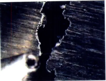
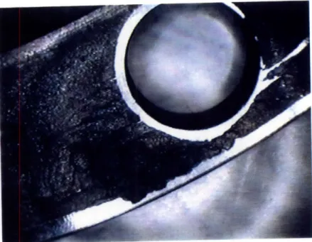
Specimen # 1 displayed several deep pits in the areas of crevice corrosion on the side with the O-ring groove (see fig. 4-1), with some penetrating nearly halfway through the ring (see fig. 4-2). On the opposite side of Specimen # 1, the corrosion was relatively superficial (fig. 4-3). On Specimen #2, the O-ring groove side displayed significant crevice corrosion but not the severe pitting of Specimen #1 (fig. 4-4); however, on its reverse side, Specimen #2 had a deep and continuous circle, cut by crevice corrosion in the vicinity of a O-ring, which was seated against the flat surface of the specimen (fig. 4-5).
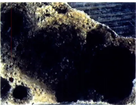
Under closer examination, Specimen # 1 revealed several other interesting attributes. First, the severity and shape of the pits which were present; certain areas of the rings had been essentially dissolved (fig. 4-6 thru 4-9), and many of the resulting pits were quite cavernous in the interior of the specimen. These pits can propagated deep into the metal of the ring before breaching the surface of the specimen (fig. 4-2). This type of pitting behavior is suggestive of the activity of Gallionella aerobic iron bacteria, which exude hydrated metal oxide and can concentrate chloride (see Chapter 3). While this was not conclusive, it was suggestive.
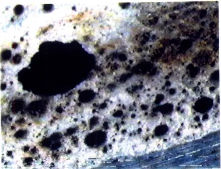
The corroded surfaces of the second specimen did not exhibit the multitude of
cavernous pits which characterize specimen # 1. Instead, the areas of corrosion appeared much more uniform, with most pits presenting a much more rounded, hemispherical shape (fig. 4-10
11). Similar pits were also present on specimen #1 in smaller numbers (fig. 4-12). However, while most of the pits were not cavernous, such pits were present in certain areas of specimen #2 (fig. 4-13 and 4-14). Just as the deep, cavernous pits are suggestive of Gallionella, the rounded, hemispherical shape is typically associated with the sulfate reducing bacteria (SRB),
Desulfovibrio and Desulfomaculum. Additionally, on both specimens, there were bright and
shiny surfaces in the areas of most severe corrosion and rings of different colors around some of the pits; both of these phenomena have been observed with SRB influenced corrosion.
III. SUMMARY
After my analysis of these two specimens of corroded materials, I concluded several observations could be made and possible explanations postulated. First, the base material was indeed 316L Stainless Steel and could therefore reasonably have been expected to display good crevice corrosion resistance in a seawater environment. Second, the severity of the corrosive attack suggests that some additional factor was present besides a purely electro-chemical attack upon the material. Thirdly, microscopic examinations of the corroded surfaces revealed pit structures and surface coloration patterns which are consistent with two different types of bacteria, the aerobic iron oxidizing bacteria Gallionella and the anaerobic sulfate reducing bacteria Desulfovibrio and Desulfomaculum. The accelerated corrosion produced by these microbes could explain the uncharacteristically poor corrosion resistance of this stainless steel.
In an attempt to confirm or deny my hypothesis that microbiologically influenced corrosion was the explanation behind this crevice corrosion problem, I next tried to reproduce this crevice corrosion in a laboratory setting, comparing the effects of biologically active
seawater with that of sterilized seawater on stainless steel samples. The results of this experiment are reported in the next chapter.
Endnotes for Chapter 4
1.Dexter, Stephen C. Handbook Of Oceanographic Engineering Materials. (University of Delaware, 1979) p.9 6.
Figure 4-1: Specimen #1 Cavernous Pit (20X magnification)
Figure 4-3: Specimen # 1 Reverse Side (20X magnification)
Figure 4-5: Specimen #2 Reverse Side (20X magnification)
Figure 4-6: Specimen #1 Cavernous Pit (100X magnification)
M& I~l: t
Figure 4-7: Specimen #1 Deep Pits (100X magnification)
Figure 4-9: Specimen #1 Deep Edge Pits (100X magnification)
Figure 4-11: Specimen #2 Hemispherical Pits (20X magnification)
Figure 4-13: Specimen #2 Deep Pits (100X magnification)
Chapter 5: Laboratory Crevice Corrosion Test
In an attempt to test my hypothesis that this crevice corrosion phenomenon was microbiologically influenced, I conducted a laboratory crevice corrosion test using the procedures of ASTM G78-89 discussed in Chapter 2. I compared the corrosion between a
specimen immersed in biologically active seawater versus a specimen immersed in seawater which had been sterilized using heat.
I. PROCEDURE
To conduct this test, I obtained two 316 Stainless Steel specimens from the machine shop at the Woods Hole Oceanographic Institute, which had fabricated the original rings for the instrument. The specimen dimensions were approximately 6.5 cm x 5 cm x 1 cm; the machine shop drilled a cm diameter hole through the center of each specimen. Surface preparation was in accordance with G78; the surface was ground with 120-grit SiC abrasive paper and pickled in acetone for 24 hours.
Each sample was placed in a two gallon bath on 6 March 1996 in the Welding
Technology Laboratory at MIT and removed on 6 May 1996. Temperature was in the normal ambient range of 650 to 750 F, and sterile distilled water was used to compensate for the small amount of evaporation which took place. Both samples were kept thoroughly mixed using aquarium air pumps. Each sample was monitored daily for any problems or abnormal conditions; none were noted in the course of the experiment.
The multiple crevice washers used in the experiment were fabricated of Delren plastic by the Woods Hole shop in accordance with Figure 2a of ASTM G78; this was the same material used for the spacers against which the original stainless steel rings were seated. The test specimens were assembled using non-metallic fasteners and washers, then torqued to 9 Nm.
II. EXPERIMENTAL RESULTS
During the course of the experiment, I observed indications that some corrosion was taking place within the assemblies, as brown corrosion trails were observed from both specimens after about one month. However, following disassembly at the conclusion of the test, it became immediately apparent that this corrosion was occurring on the rough surface within the drilled holes, not on the smooth, prepared surface beneath the multiple crevice washers.
First., I examined the surface of the specimen from the sterile seawater bath, again using the Hi Scope Compact Micro Vision System video microscope. A scan at 20X magnification revealed a pristine surface; there was absolutely no indication of where the crevices had been beneath the washer (see figs. 5-1 and 5-2). I was not particularly surprised at this result; 316 Stainless Steel should exhibit good crevice corrosion resistance against a strictly chemical attack, especially in the oxygen saturated environment produced in a bath open to the atmosphere.
Next, I turned my attention to the specimen which had been in the biologically active seawater bath. Upon disassembly, I noted an area of discoloration beneath the crevice washer for approximately 1200 around the center hole. Examining this area using the video microscope on 20X magnification, it appeared to be the results of corrosion products from within the center hole which had coated the exposed surface between the crevices formed by the multiple crevice
washer (figs. 5-3 and 5-4). Examination of this border area in 100X (figs. 5-5 and 5-6) also seemed to support this conclusion. The surface abrasions produced by the initial grinding are undisturbed even in the discolored areas; the brown discoloration is an overlay, not a reaction with the surface. No significant large scale crevice corrosion had occurred on this specimen. For further, confirmation, I shifted to a Nikon Laser Microscope (Model ILM 11) and a
magnification of 600X. As figures 5-9 and 5-10 clearly show, there is no discontinuity at the boundaries of the area which was beneath the crevice washer. Measurements of the surface height variation, using a Nikon Measurescope (Model MM-11) showed no significant variation between the areas beneath the washer and the exposed areas.
The one interesting feature on this otherwise disappointing specimen was the formation of a pit just below the inner edge of the crevice formers; it is visible in the center of fig. 5-3 and at the top of fig. 5-4. Examining this at higher magnifications, it appeared this could be the inception of a crevice attack (figs. 5-7 and 5-8); perhaps if the exposure had continued for another several months, a significant loss of metal would have occurred. Figure 5-11 shows the pit at 600X magnification on the laser microscope, while figure 5-12 is a record of its height profile. The average depth of this pit was measured with the laser microscope as 12 microns and a width of 314 microns.
III. SUMMARY
The overall results of my attempt to reproduce the accelerated crevice corrosion attack and confirm the presence of microbes as a casual factor were disappointing. While the sterile seawater specimen did not show any significant crevice corrosion, neither did the biologically
active specimen. It did display the formation of a single pit at the edge of the crevice region, suggesting that with additional time, more significant corrosion might have occurred.
Since I was unable to reproduce the rapid corrosion of 316 Stainless Steel under laboratory conditions, it cannot be said that this experiment either supports or disproves my hypothesis that the example of crevice corrosion being analyzed is microbiologically influenced. However, these results are also not inconsistent with the possibility suggested in Chapter 4, that a combination of aerobic iron oxide bacteria and anaerobic sulfate reducing bacteria were
responsible, as it is possible the experiment failed to provide the environmental conditions required for the later to thrive.
Figure 5-1: Sterile Seawater Specimen (20X magnification)
Figure 5-3: Active Seawater Specimen (20X magnification)
Figure 5-5: Active Seawater Specimen (100X magnification)
Figure 5-7: Active Seawater Pit (60X magnification)
Figure 5-9: Active Seawater Specimen (600X laserscope magnification)
Figure 5-11: Active Seawater Pit (600X laserscope magnification)
Chapter 6: Conclusions
I. CONCLUSIONS FROM ANALYSIS
Based on the analysis of the corrosion-damaged components and the results of the laboratory corrosion test, I have concluded that this phenomenon is a case of microbiologically influenced crevice corrosion. The rate of corrosion which took place during the time the instrument was deployed was far in excess of the maximum predicted rate of crevice corrosion for 316 Stainless Steel in seawater. Metallurgical analysis confirmed that the base metal was indeed 316 Stainless Steel. Microscopic visual analysis revealed two different pitting patterns. The deep, cavernous pits are characteristic of aerobic iron oxide bacteria such as Gallionella, while the rounded, hemispherical pits are characteristic of sulfate reducing bacteria such as Desulfovibrio and Desulfomaculum. The presence of both types of bacteria lead me to conclude that a slime is forming within the crevice which harbors them both; the aerobic bacteria
consume the oxygen and concentrate chlorides which produces the anaerobic conditions
required by the sulfate reducing bacteria. The existence of slimes harboring both iron oxide and sulfate reducing bacteria is well documented in the literature on microbiologically influenced corrosion. In this particular instance, the presence of a zinc for cathodic protection could also have contributed to the severity of the attack by inhibiting the reformation of the passivating layer on the stainless steel components, after the initial layer was penetrated by the bacterial attack.
The failure of the laboratory experiment to produce significant crevice corrosion is consistent with the above conclusion if the presence of sulfates to support the sulfate reducing
bacteria is also considered. The clean seawater used in the laboratory test was presumably essentially free of sulfates; however, during the year in which the actual instrument was exposed in the open ocean, it is quite possible that some local environmental change provided the sulfates necessary to start the accelerated corrosive process. A local pollution event from passing
shipping, a plankton bloom in the area, or even local volcanic activity (the Washington region is comparatively active in this regard) could have increased the local sulfate levels. There is also circumstantial evidence in the corrosion literature to support a correlation between sulfate reducing bacteria corrosive activity and phosphate or nitrate pollution in water. The requirement of an additional environmental enabling factor would explain the intermittent nature of the phenomenon. Some instruments are deployed for long periods of time and show no evidence of corrosion because the enabling local environmental change does not take place. Other
instruments, deployed in the same area for the same amount of time, experience severe corrosion because the conditions to initiate the rapid corrosive attack by the combined bacterial types are met.
II. RECOMMENDATIONS FOR PREVENTION
Based on the conclusion stated above, what recommendations can be made regarding prevention of this rapid crevice attack? First, and most obvious, the amount and tightness of any crevices should be minimized; this design change has been made on subsequent instruments with some success. A more open crevice often prevents the necessary hostile chemistry from forming. Second, discontinue the use of zincs; stainless steel in an oxidizing environment functions by forming a passive film. A zinc designed to prevent corrosion would also tend to