Publisher’s version / Version de l'éditeur:
Canadian Geotechnical Journal, 41, December 6, pp. 997-1010, 2004-12-01
READ THESE TERMS AND CONDITIONS CAREFULLY BEFORE USING THIS WEBSITE. https://nrc-publications.canada.ca/eng/copyright
Vous avez des questions? Nous pouvons vous aider. Pour communiquer directement avec un auteur, consultez la première page de la revue dans laquelle son article a été publié afin de trouver ses coordonnées. Si vous n’arrivez pas à les repérer, communiquez avec nous à PublicationsArchive-ArchivesPublications@nrc-cnrc.gc.ca.
Questions? Contact the NRC Publications Archive team at
PublicationsArchive-ArchivesPublications@nrc-cnrc.gc.ca. If you wish to email the authors directly, please see the first page of the publication for their contact information.
NRC Publications Archive
Archives des publications du CNRC
This publication could be one of several versions: author’s original, accepted manuscript or the publisher’s version. / La version de cette publication peut être l’une des suivantes : la version prépublication de l’auteur, la version acceptée du manuscrit ou la version de l’éditeur.
For the publisher’s version, please access the DOI link below./ Pour consulter la version de l’éditeur, utilisez le lien DOI ci-dessous.
https://doi.org/10.1139/T04-048
Access and use of this website and the material on it are subject to the Terms and Conditions set forth at
Uncoupled axial, flexural, and circumferential pipe-soil interaction
analyses of partially supported jointed water mains
Rajani, B. B.; Tesfamariam, S.
https://publications-cnrc.canada.ca/fra/droits
L’accès à ce site Web et l’utilisation de son contenu sont assujettis aux conditions présentées dans le site LISEZ CES CONDITIONS ATTENTIVEMENT AVANT D’UTILISER CE SITE WEB.
NRC Publications Record / Notice d'Archives des publications de CNRC:
https://nrc-publications.canada.ca/eng/view/object/?id=ca3398be-2571-4b47-9a06-4491ccd58593 https://publications-cnrc.canada.ca/fra/voir/objet/?id=ca3398be-2571-4b47-9a06-4491ccd58593Uncoupled axial, flexural, and circumferential
pipe–soil interaction analyses of partially
supported jointed water mains
Balvant Rajani and Solomon Tesfamariam
Abstract: Pipelines used in the distribution of potable water are a vital part of everyday life. The pipelines buried in
soil–backfill are exposed to different deleterious reactions; as a result, the design factor of safety may be significantly degraded and, consequently, pipelines may fail prematurely. Proactive pipeline management, which entails optimal maintenance, repair, or replacement strategies, helps increase the longevity of pipelines. The effect of different deterio-ration mechanisms and operating conditions needs to be understood to develop good proactive management practices. In this paper, a Winkler-type analytical model is developed to quantify the contributions of different stress drivers, e.g., pipe material type and size, bedding conditions, and temperature. Sensitivity analyses indicate that the extent of the un-supported length developed as a result of scour has a significant influence on the flexural pipe–soil response. As well, plastic pipes tolerate less loss of support than metallic pipes.
Key words:jointed water mains, Winkler model, pipe–soil interaction, elastoplastic soil.
Résumé : Les conduites utilisées pour la distribution de l’eau potable constituent une partie vitale de la vie de tous les
jours. Les conduites enfouies dans un remblai de sol sont exposées à différentes réactions nuisibles, et il en résulte une dégradation du coefficient de sécurité utilisé pour le calcul et en conséquence les conduites se brisent prématurément. La gestion proactive des conduites qui comporte des stratégies optimales de maintenance, de réparation, ou de rempla-cement aide à accroître la longévité des conduites. L’effet de différents mécanismes de détérioration et conditions d’opération doit être bien compris de façon à développer de bonnes pratiques de gestion proactive. Dans cet article, on a développé un modèle analytique de type Winkler pour quantifier les contributions de différentes sources de contrain-tes, e.g., type de matériau et dimension de la conduite, conditions du coussin, et température. Des analyses de sensibi-lité indiquent que l’importance de la longueur non supportée qui se développe à la suite de l’érosion a une influence significative sur la réaction conduite–sol en flexion. Également, les conduites en plastique tolèrent moins de perte d’appui que les conduites métalliques.
Mots clés :conduites maîtresses d’eau articulées, modèle Winkler, interaction sol–conduite, sol élasto-plastique. [Traduit par la Rédaction] Rajani and Tesfamariam 1010
Introduction
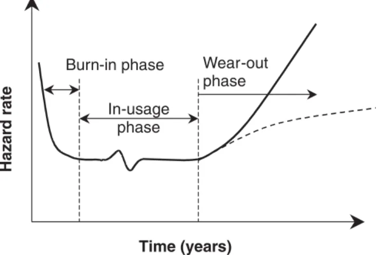
Understanding failure mechanisms of deteriorating infra-structure is paramount for the proactive management of in-frastructure assets. Exposure of water mains to aggressive environmental conditions and deleterious reactions can lead to significant deterioration so as to undermine their ability to reliably deliver safe drinking water. The life cycle of a typi-cal buried pipe is described by the so-typi-called “bathtub” curve as shown in Fig. 1. It describes the instantaneous failure probability (hazard function), and the bathtub curve often distinguishes between three phases in the life of a pipe. The first phase, also known as the “burn-in” phase, describes the
period right after installation, in which breaks occur mainly as a result of faulty installation or faulty pipes. These breaks emerge gradually and are fixed in a declining frequency. Once the system is purged of these “early” problems, the pipeline enters phase two, in which the pipe operates rela-tively trouble free, with a low failure frequency resulting from random phenomena such as unusual heavy loads and third-party interference. The third phase, also called the “wear-out phase,” depicts a period of increasing failure fre-quency due to pipe deterioration and ageing. Not every pipe experiences every phase, and the length of the phases may vary dramatically for various pipes and under various condi-tions. Alternatively, the various phases in the deterioration of structural reliability (expressed here as the factor of safety) that ultimately lead to the failure of the water main are shown in Fig. 2. Older water mains are usually made of pit- or spun-cast iron (CI), and the newer mains are largely made of ductile iron (DI) or polyvinyl chloride (PVC). In an aggressive environment, corrosion in CI takes the form of graphitization (Makar and Rajani 2000), and pitting takes place in DI pipes. PVC water mains have not been used long enough to establish a definite deterioration mechanism.
Received 26 August 2003. Accepted 13 April 2004. Published on the NRC Research Press Web site at http://cgj.nrc.ca on 29 October 2004.
B. Rajani1and S. Tesfamariam. Institute for Research in
Construction, National Research Council Canada, Ottawa, ON K1A 0R6, Canada.
Nonetheless, whatever the pipe materials and the associated deterioration mechanisms, it is assumed that structural strength will decrease, say, as a consequence of corrosion pitting, graphitization, fracture, creep, or material softening. It is further assumed that a leak will develop as soon as the pipe wall is breached. The leak will in turn scour the sur-rounding bedding and undermine the soil support to the pipe. The size of the corrosion pit and the extent to which the bedding support is lost (“unsupported” length) will lower the design factor of safety. An arch is likely to form in sandy soils (backfills); if the leak occurs at the pipe invert or crown, analysis is not required because the pipe is not loaded. A leak at the crown in clayey soils is likely to un-load the pipe initially, but as the soil becomes saturated the clay is likely to cave in and impose earth loads on the pipe. On the other hand, the proposed model allows for any load (q) on the unsupported pipe length, i.e., if arching merits consideration, then the load can be reduced. Consequently, the model considers what can be referred to as a “worst-case” scenario.
Three ingredients required to develop frost heave and hence frost load are availability of water, thermal gradient, and soil with appropriate particle size and hence pore size (Rajani and Zhan 1996). The presence of a water main leak contributes to the first of the three ingredients. All three lead to increased stresses on the pipe which were not considered in the original structural design when the pipes were
in-stalled years ago. Rajani et al. (1996), in analyzing pipe breakage, did not include an assessment of the influence of unsupported length, which could result as a consequence of water leaks and possible shrinkage due to moisture changes in bedding materials. In most cases, shrinkage-susceptible native material (predominantly clayey and silty soils in most urban areas in Canada) was used as backfill and as bedding material for CI pipe installations.
Water mains used in water distribution systems have bell and spigot connections and are referred to here as jointed pipes; typical pipe lengths are 6 m (20 ft). Elastomer gaskets at bell and spigot connections (joints) prevent leaks while permitting axial movement and slight rotation (3–4°) to accommodate limited movement of soil bedding. In the analysis described here, boundary conditions dictated by a bell–spigot joint are assumed to be ideal, i.e., free to move longitudinally and permit rotation. In practice, these move-ments are likely to be restrained as a consequence of ageing of both pipe joint and gasket materials. Longitudinal and ro-tational movements are probably restrained to a greater ex-tent in the case of cast iron pipes than for modern pipe materials. Structural design of water mains usually provides sufficient (with an accepted margin of safety) resistance against circumferential (in-plane) stresses imposed by soil overburden loads, live traffic loads, and internal pressure. Loads imposed on pipes as a result of temperature changes, soil pressures induced by frost heave, and loss of support from bedding are largely unaccounted for in the axial, flex-ural (longitudinal bending), or circumferential response analyses. The practice to exclude some of these circum-stances from routine analyses and design is acceptable as long as the margin of safety is adequate and pipes do not de-teriorate with time, leak, and develop locations with loss of bedding support or differential settlement. Ageing water dis-tribution systems, however, do indicate that pipes deteriorate with time and that there is a marked increase in the number of water main breaks with dramatic temperature differentials between the water in the pipe (1–2 °C) and the adjacent soil (10–12 °C).
The intent of this paper is to quantify the impact of the unsupported length and soil elastoplasticity on the axial and flexural responses considering pipe–soil interaction using the Winkler model. Further, the axial, flexural, and cir-cumferential stress components are consolidated from the analyses described here, and previously reported (Rajani et al. 1996; Ugural and Fenster 1987), to provide an overall picture of the response of buried water mains under the in-fluence of earth and live loads, water pressure, temperature differential, and pipe–soil interaction. Though the extent of loss of support cannot be determined in the field today, sev-eral attempts have been made by Makar (1999) for sewers using nondestructive techniques.
The axial and flexural responses of buried jointed pipe is considered to be uncoupled, and it is assumed that the pipe deformations are small and always within the elastic range. For simplicity, it is also assumed that the leak produces scour (undermined bedding) at the centre of jointed pipe of length 2L, probably representing a worst-case scenario. The soil or bedding in the pipe–soil interaction analysis is con-sidered as an elastoplastic Winkler model. Generally, the Winkler model has several shortcomings, e.g., it assumes no
Fig. 1. The “bathtub” curve of the life cycle of a buried pipe.
interaction through the soil from location to location and no interaction through shear nor volumetric effects, and the model relies on a definition of soil pressure in terms of ab-solute displacement of the pipe, not the displacement of the pipe relative to the soil. Nevertheless, given all uncertainties in modelling pipe–soil interaction, it is an acceptably simple model to permit the consideration of axial effects, longitudi-nal bending and radial effects associated with overburden pressures, internal pressure, frost loads, and thermal effects. It is important to note that the circumferential response cor-responds to that of a rigid pipe but could easily be extended to that of a flexible pipe. This consideration is appropriate for the pipe materials (CI and DI) and pipe sizes of interest here. In the analysis that follows it is assumed that thrust is positive when it results in tensile stresses in the pipe wall and negative when it results in compressive stresses. Simi-larly, a moment (longitudinal bending) is positive when there are tensile stresses on the pipe invert and negative when there are compressive stresses on the pipe invert. Ten-sile stresses in the circumferential direction are treated as positive.
Typical pipe–soil systems are considered in the sensitivity analyses to illustrate the applicability of the proposed mod-els. Pipe and soil properties and the operating conditions se-lected in these analyses are typical of those likely to be encountered in practice.
Axial pipe–soil interaction
Rajani et al. (1996) described the Winkler model for axial pipe–soil interaction of a jointed buried pipe in an elastic soil (medium). The equilibrium equation is governed by [1] ∂σ ∂ x x x k t u u u a sa − =0 <
whereσxais the axial stress, u is the axial displacement, ksais
the axial pipe–soil reaction modulus, t is the pipe wall thick-ness, and uxis the displacement required to develop ultimate
axial resistance (Committee on Gas and Liquid Fuel Life-lines 1984). The axial pipe–soil reaction modulus of the soil can be estimated using the elastic properties as suggested by Scott (1981) or empirical relationships for sand and clay as suggested by the Committee on Gas and Liquid Fuel Life-lines (1984). These relationships are as follows:
[2a] k G D sa s s elastic soil = − 4 1( υ) /2 [2b] k s ux ux sa = α u =2.5 1 .0 mm for clay− 0 [2c] k H K u u x x sa s o 0.5 2.5 5.0 mm for sand = + = − (γ )(1 ) tanδ
where D is the external diameter of the pipe, Gs is the soil shear modulus,υs is the soil Poisson’s ratio, α is the
adhe-sion coefficient, suis the undrained shear strength of clay,γs is the submerged unit weight, H is the burial depth of water mains from the surface to the centreline of the pipe, Ko is the coefficient of active resistance at rest, and δ is the
fric-tional angle between the pipe material and the surrounding backfill.
If the soil is represented as an elastoplastic material (Fig. 3) and the soil deformation exceeds the limiting axial displacement, u = ux, then the governing equilibrium
equa-tion is [3] ∂σ ∂ x x x x F t u u a − =0 ≥
where Fx is the ultimate axial resistance and is given by
[4] Fx =k usa x
Equations [1] and [3] are applicable to a pipe that is fully supported longitudinally and radially (normal to the cir-cumferential direction). As discussed earlier, the bedding of a leaky pipe is likely to be scoured, causing the pipe to lose support. This situation necessitates that the problem be solved piece-wise in three regions, i.e., unsupported pipe length (b), pipe embedded in an elastic soil (d ), and remain-ing pipe length in plastic soil ( f ) (Fig. 4). The soil is repre-sented as a Winkler elastoplastic material.
The axial response (solution to eq. [1]) of the supported pipe length d is described by
[5] ud =C1aexp(−γxd)+C2aexp(+γxd)
where ud is the axial displacement of the pipe embedded in
the elastic soil; C1a and C
2a are axial pipe–soil interaction
constants; and γ is the reciprocal of the axial characteristic length, given by [6] γ υ β υ 2 2 1 1 2 1 1 = + + + k E t E E D t sa p {[ p s/ ( s) p]( / )}
whereυpis Poisson’s ratio of the pipe,β1is a constant as de-fined in Rajani et al. (1996), Esis the elastic modulus of the
soil, and Ep is the elastic modulus of the pipe.
The axial response of the portion of the pipe supported by elastoplastic soil is given by
[7] u F x tE F x T x F f x f f f = 2 + 1 + + 2 2 p a p a α ∆
where uf is the axial displacement of the pipe embedded in
the elastoplastic soil, Ep is the pipe elastic modulus, and F1a
and F2a are constants. Temperature change in the soil is
tured by the termαp∆Txf, whereαpis the linear thermal
ex-pansion coefficient of the pipe material,∆T is the maximum temperature difference between the water and the surround-ing soil, and xf is the longitudinal coordinate system for soil
in plastic region (Fig. 4).
Similarly, the unsupported pipe length b is an axially loaded prismatic element, and its response is described by [8] ub =B x1a +α ∆p T xb+B2a
where ub is the axial displacement of the unsupported pipe,
B1aand B2a are constants, and x is the distance along the pipe
from the centreline. Symmetry considerations require that u xb( =0)=0, and consequently B2a = because unsupported0
length is assumed to form at the centre of the pipe segment. The other boundary conditions are essentially compatibility requirements for deformations at transition points from por-tions of pipe within different regions of soil behaviour, i.e., u xb( b =b) =u xd( d = 0 u x), b′( b =b) =ud′ (xd = 0), u xd( d = d)
= u xf( f = 0 u x), d′ ( d = d)= u xf′( f = 0), andσxa(xf = f ) = 0,
whereσxa is the axial stress. The unknown constants B1a, C1a,
C2a, F1a, and F2a can be obtained by applying these boundary
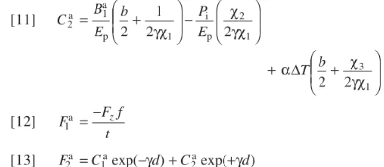
conditions: [9] B F d t P E T x 1 4 5 2 4 6 4 2 a i p p = − + − χ χ χ χ χ χ α ∆ [10] C B E b P E 1 1 1 2 1 2 1 2 2 a a p i p = ⎛ − ⎝ ⎜ ⎜ ⎞ ⎠ ⎟ ⎟ + ⎛ ⎝ ⎜ ⎜ ⎞ ⎠ ⎟ ⎟ γχ χ γχ + ⎛ − ⎝ ⎜ ⎜ ⎞ ⎠ ⎟ ⎟ α χ γχ ∆T b 2 2 3 1 [11] C B E b P E 2 1 1 2 1 2 1 2 2 a a p i p = ⎛ + ⎝ ⎜ ⎜ ⎞ ⎠ ⎟ ⎟ − ⎛ ⎝ ⎜ ⎜ ⎞ ⎠ ⎟ ⎟ γχ χ γχ + ⎛ + ⎝ ⎜ ⎜ ⎞ ⎠ ⎟ ⎟ α χ γχ ∆T b 2 2 3 1 [12] F F f t z 1a = − [13] F2a =C1aexp(−γd)+C2aexp(+γd)
whereχ1,χ2, andχ3are as defined by Rajani et al. (1996) to account for axial pipe movement, internal water pressure, and temperature change, respectively; Pi is the internal water pressure; αp is the linear thermal expansion coefficient of
the pipe material; and Fz is the maximum lateral soil
resis-tance per unit length. The constants χ4, χ5, and χ6 are as follows:
[14a] χ4 = +(1 bγχ1) exp(γd)+ −(1 bγχ1) exp(−γd) [14b] χ5 = − +2 exp(γd)+exp(−γd)
[14c] χ6 = −2χ3+(bγχ1+χ3) exp(γd)
−(bγχ1−χ3) exp(−γd) The axial stress responses in the three different regions of soil behaviour can be expressed in terms of “stress drivers,” i.e., axial pipe movement, internal water pressure, and tem-perature change: [15a] σx x f F t x f b d x b d f a = ( − ) for ( + )≤ <( + + ) [15b] σ χ ∂ ∂ χ χ α x E d u x P E T a p i p p = 1 + 2 − 3 ∆ for b≤ <x (b+d) [15c] σ χ χ χ χ χ χ α x x F d t P E T a i p p = −2 + − 4 5 2 4 6 4 ∆ for 0≤ <x b where σxa is the axial stress. If the soil yields beyond the
plastic limit, i.e., ud > ux, the temperature change will not
have any influence on the axial stress as shown by eq. [15a]. This solution is similar to that developed by Rajani et al. (1996) except that the soil supporting medium is considered as elastoplastic and there is an added consideration for the loss of bedding support as a consequence of scour developed from a leaky pipe. The solution reverts to that previously ob-tained by Rajani et al. (1996) when the unsupported length, b, is zero and the soil is elastic.
Sensitivity analyses: axial stress
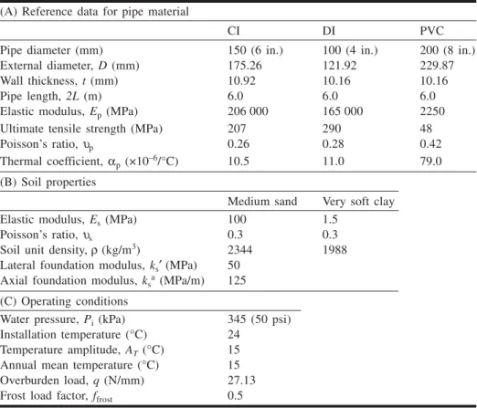
A sensitivity analysis was carried out to investigate the axial response of buried pipe to different pipe materials, pipe diameters, soil types, and soil temperatures close to the pipe. A 150 mm (6 in.) CI pipe buried in medium sand with ksa =
125 MPa/m was selected as a reference case (Table 1) to gauge the sensitivity of the axial pipe–soil system to varia-tions of different parameters.
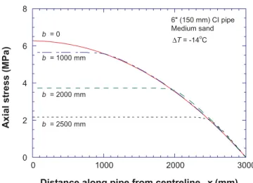
The axial stress profile for a 150 mm diameter CI main shown in Fig. 5 indicates that the axial stress decreased as the unsupported length increased, since the pipe length that is constrained from movement decreases. Similar responses are observed as unsupported pipe lengths increase and pipe diameters decrease (Fig. 6) or if the soil temperatures close to the pipe decrease (Fig. 7). Axial stresses induced at the pipe–soil interface will be lower in large-diameter pipes be-cause of a proportional increase in contact surface area. This is expected because the remaining pipe length that is sub-jected to axial restraint decreases as the unsupported pipe length increases.
Figure 8 shows the maximum axial stress (expressed as a percentage of the ultimate tensile strength) induced in differ-ent pipe materials (CI, DI, and PVC) as a consequence of temperature differential (between soil temperature and tem-perature of water in the pipe). Although there are no appre-ciable differences between the axial responses of CI and DI pipes, the PVC pipe shares a significant proportion (7% of the ultimate stress at ∆T of –14 °C) of the stress because of its higher thermal expansion coefficient and lower elastic modulus.
Axial stresses in the pipe increase (Fig. 9) as the soil be-comes stiffer, i.e., higher axial foundation moduli, for any specific unsupported pipe length. As explained earlier, this increase is accentuated at shorter unsupported lengths be-cause more of the pipe surface in contact with the soil is restrained. The role of elastoplastic behaviour of the soil shown in Fig. 10 corresponds to a pipe with an unsupported length of b = 500 mm and clearly illustrates that
consider-ation of elastoplasticity increases the axial stresses induced in the pipe compared with elastic analysis only. Elastoplastic response of the soil was artificially induced in this example by increasing the temperature difference (–56 °C) by four times the value (–14 °C) used in the rest of analyses to illus-trate the fact that a large temperature differential would have to exist to induce significant stress.
Flexural pipe–soil interaction
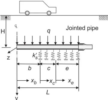
A pipe buried at constant depth in soil backfill or bedding with uniform geotechnical properties should not be normally subjected to flexural or bending deformations or stresses in the longitudinal direction. Loss of bedding support near the pipeline under circumstances described earlier, however, subjects the pipe to flexural stresses. The total load, q, im-posed on the unsupported length of the pipe is the earth load together with the traffic and frost loads. The soil near the un-supported pipe region may exceed the elastic displacement limit (vu) and develop plastic deformations if the overburden
loads or unsupported length are high enough. Prior to the de-velopment of solutions for a jointed pipe, simple solutions considering the supported portion of the pipe as an infinite beam (whenλ[L – (b + c)] > π, where λ is the reciprocal of the flexural characteristic length as defined in eq. [18]) on an elastoplastic foundation (Fig. 11) were obtained to deter-mine if there was merit to incorporating soil elastoplasticity. These simple solutions indicated that soil elastoplasticity is significant for typical pipe–soil characteristics encountered in the water distribution systems when the unsupported
(A) Reference data for pipe material
CI DI PVC
Pipe diameter (mm) 150 (6 in.) 100 (4 in.) 200 (8 in.)
External diameter, D (mm) 175.26 121.92 229.87
Wall thickness, t (mm) 10.92 10.16 10.16
Pipe length, 2L (m) 6.0 6.0 6.0
Elastic modulus, Ep(MPa) 206 000 165 000 2250
Ultimate tensile strength (MPa) 207 290 48
Poisson’s ratio,υp 0.26 0.28 0.42
Thermal coefficient,αp(×10–6/°C) 10.5 11.0 79.0
(B) Soil properties
Medium sand Very soft clay
Elastic modulus, Es(MPa) 100 1.5
Poisson’s ratio,υs 0.3 0.3
Soil unit density,ρ (kg/m3) 2344 1988
Lateral foundation modulus, ks′ (MPa) 50 Axial foundation modulus, ksa(MPa/m) 125
(C) Operating conditions
Water pressure, Pi(kPa) 345 (50 psi)
Installation temperature (°C) 24 Temperature amplitude, AT(°C) 15
Annual mean temperature (°C) 15 Overburden load, q (N/mm) 27.13 Frost load factor, ffrost 0.5
Table 1. Reference data for typical cast iron (CI), ductile iron (DI), and polyvinyl chloride
length is greater than 2 m and rigid body movement is per-mitted. Thus, two distinct regions of soil in contact with the pipe can be characterized as plastic and elastic, where xcand
xerepresent the coordinate axes of regions c and e,
respec-tively, in Fig. 11. The pipe in these circumstances can be modelled as a beam on an elastoplastic foundation (bepf) with partial support.
Frost load (Rajani and Zhan 1996) can be accounted for in a simple form as a multiple of the frost load factor ( ffrost) of the soil load. The frost load multiple, ffrost, ranges from 1,
where there is no frost load, to 2, the maximum expected frost load.
The equilibrium equation for the portion of the pipe sup-ported by elastic bedding is represented by a Winkler beam on an elastic foundation (bef) (Hetényi 1946):
[16] E I v x k v zz e e p s d d 4 4 + ′ =0
where Izzis the second moment of inertia of the pipe around
the z axis, ve is the pipe vertical displacement in the elastic
soil region, and ks′ is the lateral elastic foundation modulus of the soil. The general solution for ve is
[17] ve =exp(λxe)(E1cosλxe+ E2sinλxe)
+ exp(−λxe)(E3cosλxe+ E4sinλxe) where E1, E2, E3, and E4are constants; and the reciprocal of λ is the reciprocal of the flexural characteristic length: [18] λ = k′ E Izz s p 4 4
The lateral elastic foundation modulus of the soil, ks′, in
terms of elastic soil properties can be estimated as suggested by Vesic (1961):
Fig. 5. The effect of unsupported length, b, on axial stress.
Fig. 6. The effect of pipe size and unsupported length on axial
stress.
Fig. 7. The effect of seasonal pipe temperatures on axial stress.
Fig. 8. The effect of pipe material on axial stress as a result of
[19] k E E D E Izz s s s s p 0.65 ′ = − 1 2 4 12 υ
Differentiation of vertical displacement v with respect to x gives the slope, moment, and shear, respectively, asv′ =tan ,θ −E I vp zz ′′ =Mx, and−E I vp zz ′′′ =Q, whereθ is the slope, Mx
is the bending moment, and Q is the shear force.
As stated earlier, loss of support is likely to induce soil deformations that are beyond the elastic limit, vu, and hence will induce plastic deformations in the soil immediately ad-jacent to the point of lost support. The limiting elastic defor-mation, vu, when the plastic deformations of the soil initiate
(Fig. 12) is given by [20] vu = F kz/ s′
where Fz is the maximum lateral soil resistance per unit
length.
The maximum lateral soil resistance per unit length, cor-responding to the undrained state, is computed as proposed by Trautmann et al. (1985) and Poulos and Davis (1980) for sand and clay as follows:
[21] Fz = γsDHNz for sand
[22] Fz =N Dsc u for clay
where Nz is a dimensionless resistance factor for sand, and
Nc is the bearing capacity type factor.
The factor Nc depends on the ratio of burial depth (H) to pipe diameter (D). For typical pipe sizes and burial depths, the ratio H/D can vary between 3 and 20. Rowe and Davis (1982) have shown that the value of Nc (= 11.42) is
essen-tially constant for H/D > 3. Using Vesic’s equation, Das (1995) showed that Nzis approximately 18.4 when the angle
of internal frictionφ is 30°.
Fig. 9. The effect of soil stiffness, ksa, and unsupported length on
axial stress.
Fig. 10. The effect of elastoplastic analysis on axial stress.
Fig. 11. Schematic model for partially supported pipe on
elastoplastic foundation.
The equilibrium equation for the portion of the pipe em-bedded in soil with plastic deformations (region c in Fig. 11) is given by [23] E I v x F zz c z p d d 4 4 + =0
The displacement response, vc, for the eq. [23] is
[24] v F x E I C x C x C x C c z c zz c c c = − 4 + 1 3 + 2 2 + + 3 4 24 p 6 2
where C1, C2, C3, and C4 are constants.
The vertical deflection (vb) along the unsupported length
of the pipe subjected to a uniform load (soil and live), q, can be described by the fourth-order polynomial
[25] v q x E I B x B x B x B b b zz b b b = 4 + 1 3 + 2 2 + + 3 4 24 p 6 2
where B1, B2, B3, and B4are constants.
It is assumed that there is no vertical movement at the bell–spigot joint relative to the adjacent jointed pipe and, as indicated earlier, bell–spigot joints permit rotation and hence no moment will develop. Therefore, the corresponding boundary conditions at the bell–spigot joint are v xe( e =L)= 0 andv x′′e( e =L)=0. Symmetry considerations at the centre-line dictate the boundary conditions, zero rotation, vb′(xb =0) =
0, and zero shear, v′′′b(xb =0)=0 Consequently, B. 1 and B3 are equal to zero. At xb= b and xc= 0, to satisfy continuity
and compatibility, the boundary conditions are vb(x = b) =
vc(xc = 0), vb′(xb = b) = vc′(xc= 0),v′′b(xb = b) =v′′c(xc = 0),
andv′′′b(xb= b) =v′′′c(xc= 0). Similarly, at xc= c and xe= 0, to
satisfy continuity and compatibility, the boundary conditions are vc(xc= c) = ve(xe= 0), vc′ (xc= c) = ve′ (xe= 0),v′′c(xc= c) =
′′
ve(xe = 0), and v′′′c(xc = c) = v′′′e(xe = 0). The unknowns in
eqs. [17], [24], and [25] can be determined by applying these boundary conditions. Detailed derivations and descrip-tions of the unknown terms are given in Appendix A. The unknown terms of eq. [17], B2, and B4are given in eqs. [26]
and [27]: [26] B2 F cz E Izz qb E Izz 3 3 3 2 6 4 4 1 7 2 2 = + + + + − − − + − / p λ / p λ θ θ α α θ θ α α5 [27] B C q b E I B b zz 4 4 4 2 2 24 2 = − − p
where α4–α7 andθ1–θ4 are constants.
Sensitivity analyses: flexural stress
A cursory look indicates that a number of variables influ-ence the flexural response of a partially unsupported pipe on an elastoplastic bedding. Sensitivity analyses are carried out to identify the role of the principal variables such as soil type, pipe material, and pipe diameter. The same 150 mm (6 in.) CI pipe used for the sensitivity study of axial pipe– soil interaction is used to study the flexural pipe–soil inter-action except that the lateral foundation modulus for medium sand is selected as ks′ = 50 MPa.
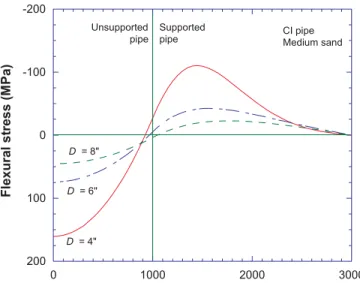
For a given unsupported length, two locations (Fig. 13) along the length of the pipe are susceptible to high stresses:
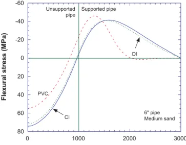
at the centreline and in the soil at the location where the pipe support ends. As expected, small-diameter mains expe-rience higher stresses (Figs. 13, 14) than large-diameter mains, and the stress differences increase as the unsupported length, b, increases (Fig. 14). The 100 mm (4 in.), 150 mm (6 in.), and 200 mm (8 in.) diameter CI pipes approach ulti-mate strength at b = 1150, 1760, and 2180 mm, respectively. The flexural stresses in CI and DI pipes are comparable (Fig. 15), as both pipes have higher moduli of elasticity than PVC. The 150 mm PVC, CI, and DI pipes approach their re-spective ultimate strengths (Fig. 16) at unsupported lengths of b = 1000, 1760, and 1880 mm. This highlights the fact that CI and DI pipes can tolerate much higher unsupported lengths than PVC pipes.
The lateral elastic foundation modulus of the soil, ks′ , is influenced by the pipe rigidity, EpIzz, and elastic modulus of
the soil. The foundation moduli, ks′ , can range between 24
Fig. 13. The effect of pipe size and unsupported length on
flex-ural stress.
Fig. 14. The effect of pipe size and unsupported length on the
and 52 MPa for medium sand and between 0.08 and 0.55 MPa for very soft clay. The flexural responses (Fig. 17) of the same pipe but buried in different soil types can be dramatically different. This difference in response is further demonstrated in Fig. 18, where the flexural stresses decrease with an increase in ks′ . The pipe effectively behaves like a simply supported beam when ks′ is very small. The flexural
stress response does not change (Fig. 18) significantly, how-ever, when the lateral foundation modulus exceeds 50 MPa.
The role of elastoplastic behaviour of the soil on flexural bending stress is shown in Fig. 19 for a pipe with an unsup-ported length of b = 1000 mm. It can be seen that slightly higher bending stresses are obtained when the bedding is modelled as an elastoplastic medium. The soil near unsup-ported pipe develops plastic deformations as the unsupunsup-ported length or overburden load increases. Though the sensitivity analysis does not show a dramatic difference in response, it
can be significant to conduct elastoplastic pipe–soil interaction analysis for flexural behaviour, depending on the specific design variables.
Circumferential (or hoop) pipe–soil
interaction
It was stated earlier that it is appropriate to consider most common pipe materials as rigid, for pipe sizes of interest in the water industry. The overburden (earth) load together with traffic and frost loads induce thrust and moment in the pipe in the circumferential (or hoop) direction. The rigid-pipe assumption considers there is no interaction support from the soil, and there is zero lateral earth pressure (Ko = 0).
This assumption will assure conservative results for the CI pipes and very conservative results for the PVC pipes. The hoop stress,σθw, for the overburden loads, q (combination of
earth, traffic, and frost load), is
Fig. 15. The effect of pipe material and unsupported length on
flexural stress.
Fig. 16. The effect of pipe material and unsupported length on
the maximum flexural stress.
Fig. 17. The effect of soil type on flexural stress.
[28] σ π θ w = ⎛ ⎝ ⎜ ⎜ ⎞ ⎠ ⎟ ⎟ q D t 3 2
(Watkins and Anderson 1999).
The hoop stress (σθPi) in a thin pipe as a result of the
inter-nal pressure is given by [29] σθP P P D t t i i e = − ⎛ − ⎝ ⎜ ⎜ ⎞ ⎠ ⎟ ⎟ ( ) 2
where Peis the external radial pressure. The radial displace-ment is constrained by the radial stiffness of the surrounding soil, and the force–displacement relation for a pipe in an in-finite medium is given by
[30] P k u E D u e r r s s r = = + θ υ ( / ) (2 1 )
where krθ is the radial soil stiffness, and ur is the radial dis-placement. There is no radial restraint in the region where the pipe is unsupported, and hence Pe= 0. It is assumed that for the typical radial displacement, the soil remains in the elastic range.
As a consequence of the Poisson’s effect on longitudinal stress, the bending hoop stressσθf is
[31] σθf = −υ σp f = −υp ⎛ ⎝ ⎜ ⎜ ⎞ ⎠ ⎟ ⎟ x x zz M D I 2
where σxf is the stress in the longitudinal direction due to
flexural action. The temperature differential (∆T) between the inside of the pipe and the surrounding soil induces a thermal hoop stress σθT:
[32] σ α υ θ T p p p o i = − E T r r ∆ 2 1( ) ln( / ) × − − − + ⎛ ⎝ ⎜⎜ ⎞⎠⎟⎟ ⎛ ⎝ ⎜ ⎜ ⎞ ⎠ ⎟ ⎟ 1 1 2 2 2 2 ln ) ln r r r r r r r r r o i o i o 2 o i ( ⎡ ⎣ ⎢ ⎢ ⎤ ⎦ ⎥ ⎥
where riis the distance from the centre of the pipe to the
in-ner wall, rois the distance from the centre of the pipe to the outer wall, and r is the distance from the centre of the pipe to any point (Ugural and Fenster 1987).
The total hoop stress because of external loads, internal pressure, temperature differential, and longitudinal bending is
[33] σθTotal σwθ σθ σθT σθf σθw σθ σθT σ p f i i = + P + + = + P + − x v
Sensitivity analyses: hoop stress
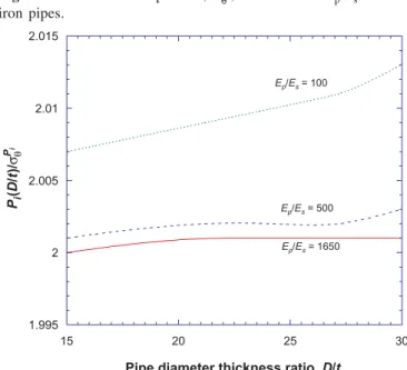
The nondimensional form of hoop stress derived using eq. [29] for CI is shown in Fig. 20 (similar plots for PVC and DI were provided by Rajani et al. 1996). Unlike for PVC and DI pipes, the analyses show that CI pipes exhibit little sensitivity to the surrounding soil stiffness, which is al-together not surprising because CI pipes are considered as rigid.
Fig. 19. The effect of soil elastoplasticity on flexural stress. Fig. 20. Variation of hoop stress,σθPi, with D/t and E
p/Esfor cast
iron pipes.
Fig. 21. Variation of hoop stress with change in soil temperature
The effect of temperature on hoop stress is a combination of the radial restraint and the thermal difference between the inside and outside surfaces of the pipe (eq. [32]). As de-picted in Fig. 21, the radial restraint is almost zero, whereas the thermal stress calculated using eq. [32] is significant (and in compression). The reason for this is that when the inside temperature is greater than the outside pipe tempera-ture, the hoop stress on the outer surface is negative (com-pressive).
Conclusions
Current structural design of new water mains is based pri-marily on circumferential (hoop) stresses imposed by inter-nal pressure and exterinter-nal loads. This design process is valid as long as the pipe is uniformly supported along its length. The deterioration (corrosion) of water mains with time, how-ever, dictates that axial and flexural (longitudinal bending) responses should be considered together with the circumfer-ential response. Furthermore, Rajani et al. (1996) showed the importance of considering temperature differential on the axial response to explain the increased number of water main breaks during periods of late spring – early winter and late winter – early spring, i.e., when the temperature differ-ence between the water and the soil–backfill close to the pipe is likely to be the highest.
In most cases a combination of circumstances leads to the failure of any one particular water main, and it is very
diffi-cult to ascertain the precise cause because all the operational data are not always known, e.g., surge pressure, pipe condi-tion, unsupported length, pit geometry. There is a high degree of uncertainty associated with all the factors contrib-uting to pipe failure because of the great spatial variability (even in a moderate size network), especially with corrosion rates. The analytical procedures developed here for jointed water mains and in combination with those developed earlier provide a means to identify the impact of different interven-ing variables on axial, flexural, and circumferential stress re-sponses. The contributions towards these stress responses from internal water pressure, temperature differential, un-supported pipe length, external loads, and pipe–soil interac-tion are summarized in Tables 2 and 3.
Sensitivity analyses indicate that the extent of the unsup-ported length developed as a result of scour has a significant influence on the flexural pipe–soil response, but the axial pipe–soil response is not negatively affected in terms of higher stress. In general, plastic pipes tolerate less loss of support than metallic pipes. In most practical situations, it is appropriate to ignore soil elastoplasticity, since its influence on pipe response is minor.
The physical deterministic model as described in this paper can be used to conduct postfailure analysis. As previ-ously mentioned, there is a high degree of uncertainty asso-ciated with all the factors contributing to pipe failure because of the great spatial variability. The physical deter-ministic model for pipe–soil interaction proposed here
Domain Internal pressure Temperature Unsupported pipe length External load Pipe–soil interaction (b + d)≤ x < (b + d + f ) — — M D I x zz 2 υp π 3 2 D t q ⎛ ⎝ ⎜ ⎜ ⎞ ⎠ ⎟ ⎟ F t x f x f ( − ) b< x < (b + d) χ2Pi χ3Epαp∆T M D I x zz 2 υp π 3 2 D t q ⎛ ⎝ ⎜ ⎜ ⎞⎠⎟⎟ χ ∂ ∂ 1E u x d p x< b χ χ χ 2Pi 5 4 ⎛ ⎝ ⎜⎜ ⎞⎠⎟⎟ χχ64 α Ep p∆T M D I x zz 2 — −2 4 F d t x χ
Table 2. Longitudinal stress components from axial and flexural responses.
Domain x > b x≤ b
Unsupported pipe length υ
p M D I x zz 2 υp M D I x zz 2 External load 3 2 D t q π ⎛ ⎝ ⎜ ⎜ ⎞⎠⎟⎟ — Internal pressure D t t P E x x − ⎛ ⎝ ⎜ ⎞ ⎠ ⎟ − − − ′′ + ′′ 2 1 2 1 2 1 1 i ββ υp sχ γ γ β χ exp( ) exp( ) Ep(1+ s)[exp(− f)+exp( f)] ⎧ ⎨ ⎪ ⎩⎪ ⎫ ⎬ ⎪ ⎭⎪ υ γ γ P D t t i⎛ − ⎝ ⎜ ⎞ ⎠ ⎟ 2 Temperature D t T E E x x 2 1 3 1 ⎛ ⎝ ⎜ ⎜ ⎠⎟⎟⎞αp∆ − pβη + υp sχ β − ′′ +γ γ ′′ exp( ) exp( ) χ1(1+υ)[exp(−γ )+exp(γ )] ⎧ ⎨ ⎩ ⎫ ⎬ ⎭ s f f + − − − − + ⎛ α υ p p p o i o i i o i o 2(1 E T r r r r r r r r r ∆ ) ln ( / ) 1 ln 1 2 2 2 2 2 ⎝ ⎜⎜ ⎞ ⎠ ⎟⎟ ⎛ ⎝ ⎜⎜ ⎞⎠⎟⎟ ⎡ ⎣ ⎢ ⎢ ⎤ ⎦ ⎥ ⎥ ln r r o i α υ p p p o i 2(1 E T r r ∆ − ) ln ( / ) × − − − + ⎛ ⎝ ⎜ ⎜ ⎞ ⎠ ⎟ ⎟ ⎛ ⎝ ⎜⎜ ⎞ ⎠ ⎟⎟ ⎡ ⎣ 1 1 2 2 2 2 2 lnr ln r r r r r r r r o i o i o o i ⎢ ⎢ ⎤ ⎦ ⎥ ⎥
provides point estimates (or fixed values) to determine the factor of safety, which is generally not sufficient. Therefore, the model requires further development to include uncertain-ties so that the probability of pipe failures at a given time can be quantified to plan maintenance and repair strategies. Possible approaches to do this are Monte Carlo simulations (Sadiq et al. 2004) and fuzzy-based methods (Guynnet et al. 2000) to evaluate the time-dependent reliability, i.e., hazard function of time to failure of buried pipes, and to identify key modelling and input parameters that contribute to the re-duction in factor of safety.
References
Committee on Gas and Liquid Fuel Lifelines. 1984. Guidelines for the seismic design of oil and gas pipeline systems. America So-ciety of Civil Engineering, New York.
Das, B.M. 1995. Principles of foundation engineering. PWS Pub-lishing Company, Toronto, Ont.
Guynnet, D.G., Come, B., Perrochet, P., and Parriaux, A. 2000. Comparing two methods for uncertainty in risk assessments. Journal of Environmental Engineering, ASCE, 125(7): 660–666. Hetényi, M. 1946. Beams on elastic foundations. University of
Michigan Press, Ann Arbor, Mich.
Makar, J. 1999. Diagnostic techniques for sewer systems. Journal of Infrastructure Systems, 5(2): 69–78.
Makar, J.M., and Rajani, B.B. 2000. Gray cast-iron water pipe metallurgy. Journal of Materials in Civil Engineering, ASCE,
12(3): 245–253.
Poulos, H.G., and Davis, E.H. 1980. Pile foundation analysis and design. John Wiley and Sons, Toronto, Ont.
Rajani, B., and Zhan, C. 1996. On the estimation of frost loads. Canadian Geotechnical Journal, 33: 629–641.
Rajani, B., Zhan, C., and Kuraoka, S. 1996. Pipe–soil interaction analysis of jointed water mains. Canadian Geotechnical Journal,
33: 393–404.
Rowe, R.K., and Davis, E.H. 1982. The behaviour of anchor plates in clay. Géotechnique, 32: 9–23.
Sadiq, R., Rajani, B., and Kleiner, Y. 2004. Probabilistic risk anal-ysis of corrosion associated failures in cast iron water mains. Reliability Engineering & System Safety, 86(1): 1–10. Scott, R.F. 1981. Foundation analysis. Prentice Hall Inc.,
Engle-wood Cliffs, N.J.
Trautmann, C.H., O’Rourke, T.D., and Kulhawy, F. 1985. Uplift force–displacement response of a buried pipe. Journal of Geo-technical Engineering, ASCE, 111(9): 1061–1076.
Ugural, A.C., and Fenster, S.K. 1987. Advanced strength and ap-plied elasticity. Elsevier, New York.
Vesic, A.S. 1961. Bending of beams resting on isotropic elastic solid. Proceedings of the American Society of Civil Engineers,
87(EM2): 35–51.
Watkins, R.K., and Anderson, L.R. 1999. Structural mechanics of buried pipes. CRC Press, New York.
Appendix A
For a medium-length beam, the governing equations given in eq. [8] and the corresponding derivatives are as follows:
ve =exp(λxe)(E1cosλxe+ E2sinλxe)+exp(−λxe)(E3cosλxe+E4sinλxe)
ve′ =λ{exp(λxe)[E1(cosλxe −sinλxe)+ E2(cosλxe−sinλxe)]
−exp(−λxe)[E3(cosλxe+sinλxe)−E4(cosλxe−sinλxe)]}
′′ = − − + −
ve 2λ2[ exp(λxe)(E1sinλxe E2cosλxe) exp( λxe)(E3sinλxe −E4cosλxe)]
′′′ = − + − −
ve 2 3 xe E xe xe E xe
1 2
λ{ exp(λ )[ (cosλ sinλ ) (cosλ sinλxe)]
+ exp(−λxe)[E3(cosλxe−sinλxe)+E4(cosλxe+sinλxe)]} It is assumed that because of the bell and spigot connection the vertical displacement and the moment are zero at the finite length of the pipe.
Similarly, at the unsupported beam and the beam supported by a plastic soil connection, to satisfy the continuity, the fol-lowing boundary conditions are solved at x = b and x′ =0:
Condition
Beam resting on
plastic foundation Unsupported beam
vc =vb C1 q b E I B b B zz 4 2 2 4 24 p + 2 + vc′ = ′vb C3 q b E Izz B b 3 2 6 p + ′′ = ′′ vc vb C2 q b E Izz B 2 2 2 p + ′′′ = ′′′ vc vb C1 q b E Izz 2 p
At the intersection of the beam supported by plastic soil and elastic soil, to satisfy the continuity, the following boundary conditions are solved at xc= c and xe= 0:
Using the aforementioned governing equations and bound-ary conditions, the solution can be shown to be
B2 F cz E Izz qb E Izz 3 3 3 2 6 4 4 1 7 2 2 = + + + + − − − + − / p λ / p λ θ θ α α θ θ α α5 B C q b E I B b zz 4 4 4 2 2 24 2 = − − p E1 =θ3+θ4B2 E2 =α4+α5B2 E3 = − −θ2 θ1B2 E4 =α6+α7B2 C q b E Izz 1 2 = p C q b E Izz B 2 2 2 2 = + p C q b E Izz B b 3 2 2 2 = + p C E E F c E I C c C c C c z zz 4 1 3 4 1 3 2 2 3 24 6 2 =( + )+ − − − p
whereα4,α5, α6, and α7 are α λ λ λ λ 4 = F c − − − + E I c c q b E I z zz zz 24 3 3 3 24 2 2 3 p p ( ) ×(3+3c2 2λ +6cλ+3bcλ2+3bλ+b2 2λ) α λ λ λ 5 2 4 4 1 4 = c + b + α λ λ λ λ 6 3 2 2 3 24 3 3 24 = F c − + − + E I c c q b E I z zz zz p p ( ) ×(3+3c2 2λ −6cλ+3bcλ2 −3bλ+b2 2λ) α λ λ λ 7 2 4 4 1 4 = c + b −
andθ1,θ2, θ3, andθ4 are
θ α λ α λ λ λ 1 = 5 + 7 − 2 2 1 2 2 exp( ) ( cos ) cos sin e e e e θ α λ α λ λ λ 2 4 6 2 2 1 2 2 = exp( )+ ( − cos ) cos sin e e e e
θ = θ3 2exp(−2λe)−α4tanλe−α6exp(−2λe) tanλe θ4 =θ1exp(−2λe)−α5tanλe−α7exp(−2λe) tanλe
List of symbols
AT temperature amplitude
b unsupported pipe length
Bia, Cia, Dia, Fia axial pipe–soil interaction constants (i = 1, 2)
c extent of soil in elastoplastic state (lateral)
d extent of soil in elastic state (axial)
D outside pipe diameter
e extent of soil in elastic state
Ei flexural pipe–soil interaction constants (i = 1–4)
Ep elastic modulus of pipe
Es elastic modulus of soil
f extent of soil in elastoplastic state (axial)
ffrost frost load factor
Fx ultimate axial soil resistance
Fz maximum lateral soil resistance per unit length
Gs soil shear modulus
H burial depth of water mains
Izz pipe second moment of inertia around the z axis
krθ radial soil stiffness
ksa axial pipe–soil reaction modulus
ks′ lateral soil elastic foundation modulus Ko coefficient of active resistance at rest
L half jointed pipe length
Mx bending moment
Nz dimensionless resistance factor for sand
Nc bearing capacity type factor for clay
Pe external radial pressure
Pi pipe internal pressure
q overburden load
Q shear force Condition Beam on elastic foundation Unsupported beam
ve =vc E1+ E3 −F c + + + + E I C c C c C c C z zz 4 1 3 2 2 3 4 24 p 6 2 ve′ = ′vc λ(E1+ E2+ E3+ E4) −F c + + + E I C c C c C z zz 3 1 2 2 3 6 p 2 ′′ = ′′ ve vc –2λ2(E2– E4) −F c + + E I C c C z zz 2 1 2 2 p ′′′ = ′′′ ve vc 2λ3(–E1+ E2+ E3+ E4) −F c + E I C z zz p 1
r distance from the centre of the pipe to any point
ri distance from the centre of the pipe to the in-ner wall
ro distance from the centre of the pipe to the outer wall
su undrained shear strength of clay
t pipe wall thickness
u axial displacement
u ub, b′ pipe axial displacement and strain in the
un-supported region
u ud, d′ pipe axial displacement and strain in the
elas-tic region
uf,uf′ pipe axial displacement and strain in the
elastoplastic region
ur pipe radial displacement
ux soil displacement at ultimate axial resistance
v vertical displacement
v vb, b′ ′′ ′′′ pipe vertical displacement, slope, curvature,vb,vb
and change in curvature in the unsupported re-gion
v vc, c′ ′′ ′′′ pipe vertical displacement, slope, curvature,vc,vc
and change in curvature in the elastoplastic re-gion
v ve, e′ ′′ ′′′ pipe vertical displacement, slope, curvature,ve,ve
and change in curvature in the elastic region
vu soil displacement at the ultimate lateral resis-tance
x distance along pipe from the centreline
xb, xc, xd, xe, xf longitudinal coordinate systems for axial (Fig. 4) and lateral (Fig. 11) pipe-soil interac-tion
α adhesion coefficient
αi flexural pipe–soil interaction constants (i = 4–7) αp linear thermal expansion coefficient of pipe
material
β1 axial pipe–soil interaction constants
δ frictional angle between pipe material and surrounding backfill
∆T maximum temperature difference between wa-ter and surrounding soil
φ soil internal friction angle
γ reciprocal of the axial characteristic length γs soil submerged unit weight
η ratio of elastic pipe and soil properties as de-fined by Rajani et al. (1996)
λ reciprocal of the flexural characteristic length υs Poisson’s ratio of soil
υp Poisson’s ratio of pipe
θ slope
θi flexural pipe–soil interaction constants (i = 1–4) ρ unit density soil
σxa axial stress
σxf stress in longitudinal direction due to flexural
action
σθPi hoop stress due to internal pressure
σθf hoop stress due to the Poisson’s effect of
lon-gitudinal bending
σθT hoop stress due to temperature differential
σθTotal total hoop stress
σθw hoop stress due to overburden loads