Publisher’s version / Version de l'éditeur:
Journal of Composites for Construction, 9, Jan/Feb. 1, pp. 15-24, 2005-01-01
READ THESE TERMS AND CONDITIONS CAREFULLY BEFORE USING THIS WEBSITE. https://nrc-publications.canada.ca/eng/copyright
Vous avez des questions? Nous pouvons vous aider. Pour communiquer directement avec un auteur, consultez la
première page de la revue dans laquelle son article a été publié afin de trouver ses coordonnées. Si vous n’arrivez pas à les repérer, communiquez avec nous à PublicationsArchive-ArchivesPublications@nrc-cnrc.gc.ca.
Questions? Contact the NRC Publications Archive team at
PublicationsArchive-ArchivesPublications@nrc-cnrc.gc.ca. If you wish to email the authors directly, please see the first page of the publication for their contact information.
NRC Publications Archive
Archives des publications du CNRC
This publication could be one of several versions: author’s original, accepted manuscript or the publisher’s version. / La version de cette publication peut être l’une des suivantes : la version prépublication de l’auteur, la version acceptée du manuscrit ou la version de l’éditeur.
For the publisher’s version, please access the DOI link below./ Pour consulter la version de l’éditeur, utilisez le lien DOI ci-dessous.
https://doi.org/10.1061/(ASCE)1090-0268(2005)9:1(15)
Access and use of this website and the material on it are subject to the Terms and Conditions set forth at
Modeling the behavior of fiber reinforced polymer-confined concrete columns exposed to fire
Bisby, L. A.; Green, M. F.; Kodur, V. K. R.
https://publications-cnrc.canada.ca/fra/droits
L’accès à ce site Web et l’utilisation de son contenu sont assujettis aux conditions présentées dans le site LISEZ CES CONDITIONS ATTENTIVEMENT AVANT D’UTILISER CE SITE WEB.
NRC Publications Record / Notice d'Archives des publications de CNRC:
https://nrc-publications.canada.ca/eng/view/object/?id=d92f55bb-2136-421a-ae5b-918b38f6b23f https://publications-cnrc.canada.ca/fra/voir/objet/?id=d92f55bb-2136-421a-ae5b-918b38f6b23f
Modeling the behavior of fiber reinforced polymer-confined concrete columns exposed to fire
Bisby, L.A.; Green, M.F.; Kodur, V.K.R.
NRCC-47682
A version of this document is published in / Une version de ce document se trouve dans: Journal of Composites for Construction, v. 9, no. 1, Jan/Feb. 2005, pp. 15-24
Doi: 10.1061/(ASCE)1090-0268(2005)9:1(15)
Modeling the Behavior of FRP-Confined Concrete
Columns Exposed to Fire
By Dr. L.A. Bisby 1, Dr. M.F. Green, 2 and Dr. V.K.R. Kodur, 3 Member, ASCE
Abstract: Very little information is available on the behavior of FRP materials and
FRP-strengthened concrete members in fire, and this is a primary factor hindering the widespread implementation of FRP strengthening technologies in the construction industry. This paper presents a numerical model for evaluating the fire behavior of conventionally reinforced circular concrete columns, FRP-wrapped reinforced concrete columns, and insulated FRP-wrapped reinforced concrete columns. The model is validated against data available in the literature from full-scale fire endurance tests on conventionally-reinforced concrete columns, and preliminary predictions of the model are presented and discussed. It is demonstrated that the model agrees reasonably well with experimental data obtained from tests on circular reinforced concrete columns, that it is unlikely that the structural effectiveness of FRP materials can be maintained during fire, and that the fire behavior of FRP-wrapped columns can be dramatically improved by providing supplemental insulation to the FRP.
Keywords: Reinforced Concrete, Rehabilitation, Strengthening, FRP, Fire Endurance,
Confinement, Concrete Columns.
1
Assistant Professor, Department of Civil Engineering, Queen’s University, Kingston, Ontario, Canada K7L 3N6
2
INTRODUCTION
Fibre-reinforced polymer (FRP) materials are rapidly gaining acceptance as structural materials for a range of civil engineering applications. This is particularly true for FRP as external strengthening reinforcement for concrete members. Until now, the majority of applications of these materials have been for bridges, or other structures, where performance in fire is not a primary design consideration. There is a potentially much larger market for the use of FRP materials in multi-storey buildings, parking garages, and industrial structures, where fire-safety is a key design parameter (Kodur and Baingo, 1998). Research in the area of FRP-confined concrete has advanced to the point that design guidelines are available (under ambient conditions) (ACI, 2002; ISIS, 2001) and widespread acceptance of this promising strengthening technique seems inevitable. Indeed, many existing structures have been strengthened or rehabilitated with external FRP wraps in recent years. However, before FRP reinforcement can be used with confidence in buildings, the performance of these materials during fire, and their ability to meet the fire endurance criteria set out in building codes, must be evaluated. Current design methodologies to ensure fire-safety when using FRP materials (ACI, 2002) are based on conservative assumptions and are not well founded in research. Thus, a more complete understanding of the fire behavior of FRP-confined concrete columns is required before FRP can be used with confidence in buildings.
Full-scale fire endurance tests on FRP-confined reinforced concrete columns are time-consuming and expensive. While a limited number of such tests will certainly be required for the purposes of model validation, accurate numerical models can significantly reduce the time and cost of fire endurance for FRP-confined columns. Once validated, numerical models can be 3
Senior Research Officer, Fire Risk Management Program, Institute for Research in Construction, National Research Council of Canada, Ottawa, Ontario, Canada K1A 0R6
used to conduct parametric studies to investigate the effects of varying a wide range of parameters on member performance in fire. Design guidelines can then be suggested.
This paper presents and discusses a unique numerical model that can be used to evaluate the fire behavior of conventionally reinforced concrete columns, FRP-confined reinforced concrete columns, and insulated FRP-confined reinforced concrete columns.
BACKGROUND
Several important concerns are associated with the high-temperature behavior of FRP materials for use in buildings, and these can be grouped into two broad categories: environmental and structural. Environmental concerns are generally associated with the potential combustion of the polymer matrix component of the FRP. Most FRP matrix materials are combustible and will burn when subjected to a sufficiently high heat flux. Combustion of FRP materials is thus a major concern in buildings, because it could potentially result in increased flame spread, increased fuel load, or generation of thick, black, toxic smoke (Sorathia et al., 1992). Traditional construction materials such as concrete and steel are non-combustible, and so there are typically few concerns (such as smoke generation) associated with their use in buildings. Structural concerns are associated with thermally induced degradation in the strength and stiffness of FRP materials, which can be severe at only mildly increased temperatures (Blontrock et al., 1999). Potential damage to the FRP-concrete bond is another structural concern, since bond relies heavily on the shear strength of the polymer matrix, which is severely degraded at temperatures beyond its glass transition temperature (GTT) (Katz and Berman, 2000). GTTs for common FRP used in concrete reinforcing applications typically range from 65 to 150˚C. In addition, severe differential thermal expansion between FRP and the substrate concrete could result in the development of large thermal stresses and could damage the integrity of the FRP-concrete bond.
While environmental concerns are important considerations for the use of FRP materials in structures, and a complete investigation of the hazards they may potentially create is both warranted and required, the focus of the current study is on structural fire endurance, with an emphasis on the deterioration of strength and stiffness of FRP materials at high temperature, and the consequences for FRP-confined reinforced concrete columns subjected to fire.
Material Behavior at High Temperature
Research conducted during the past 50 years has resulted in a relatively complete understanding of the variation in the thermal and mechanical properties of both steel and concrete at elevated temperature, and validated mathematical relationships to describe the observed trends are widely available (Lie, 1992). This is not true for FRP materials used in structural engineering applications. In particular, information on the high temperature behavior of FRP is essential for accurate numerical modeling of fire behavior, and is extremely scarce. For the purposes of the numerical modeling presented herein, a series of semi-empirical analytical relationships were derived to describe the deterioration of strength and stiffness of FRP with increasing temperature. The relationships are based on multi-variable least-squares regression analyses of data from tensile tests on FRP at high temperature available in the literature. The data were fitted using a sigmoid function that was used previously (Katz and Berman, 2000) to describe deterioration of the FRP-concrete bond at elevated temperature. Details of the analytical equation development will be published elsewhere.
For the purposes of illustration, Fig. 1 shows the approximate variation in strength, with increasing temperature, of concrete, reinforcing steel, and carbon/epoxy FRP. FRP are considerably more sensitive to the effects of elevated temperature, with severe degradation of
tensile strength and elastic modulus at temperatures below 400°C. This highlights the need for research into the unique high-temperature structural behavior FRP-reinforced concrete members.
NUMERICAL MODEL
Fire safety engineering is primarily concerned with the protection of life and property from fire (Lie, 1992). As such, structural fire design criteria are generally based on the minimization of fire spread, the ability to safely evacuate a structure, and the prevention of catastrophic collapse. Fire is traditionally defined in terms of a standard fire, which is a time-temperature profile chosen to represent the conditions to which a member might be subjected in the event of a severe building fire (ASTM, 2001). Thus, any model to predict the behavior of a structure or member during fire must be capable of accurately predicting temperatures within the member, and subsequently using that information to estimate the load capacity of said member. In an effort to study the heat transfer behavior and load carrying capacity of circular FRP-confined reinforced concrete columns during fire, a numerical procedure was developed and programmed for computer. The analysis consists of two main portions: a finite-difference heat transfer analysis, and a strain-equilibrium load capacity analysis.
Heat Transfer Analysis
The heat transfer analysis uses a methodology that is similar to previous work performed at the National Research Council of Canada (NRCC) for modeling the fire endurance behavior of conventionally reinforced concrete columns (Lie and Celikkol, 1991; Lie et al., 1992). The analysis uses an explicit finite-difference formulation, based on an elemental energy balance, to calculate the temperatures inside concrete members when subjected to a specified standard time-temperature curve (ASTM, 2001). It is assumed in the analysis that the column is infinitely long and that the contribution of the internal reinforcing steel to the overall heat transfer within the
member is minimal and can be neglected. Both of these assumptions have been used with success in the past (Lie and Celikkol, 1991).
The analysis is carried out by dividing the column cross-section into a series of circular elemental layers. This is shown in Fig. 2 for a quarter-section of an FRP-confined reinforced concrete column without supplemental insulation. For each layer, an energy balance is formulated, based on conservation of thermal energy, and the resulting equations are combined to yield a series of explicit finite difference equations. As an example of the equation derivation for a specific element in the cross-section, for a ring element in the interior of the FRP wrap, the change in energy stored in the element, ∆Qst, during a time interval ∆t, must be equal to the
difference between the heat into the element due to conduction, Q , and the heat out of the element due to conduction, , thus:
in out Q out in st Q Q Q = − ∆ (1)
The heat stored in the elemental layer can be described in Cartesian coordinates using:
dxdydz t T C Qst ∂ ∂ = ∆ ρ (2)
If the volume of the element is taken as Vlay, and the time interval is taken as ∆t, then for
some overall change in temperature, ∆T, the above equation can be expressed approximately as:
t T V C Qst w w lay ∆ ∆ = ∆ ρ (3)
where ρwCw is the heat capacity of the FRP wrap material (the product of density and specific heat). For a column discretized as shown in Fig. 2, Eqn. 3 can be rewritten as:
(
)
(
)
[
]
[
]
t T T x x m R C Q i m i m w w w w w st ∆ − ∆ ∆ − − = ∆ ρ 2π 1 −1 (4)where is the temperature of element m at the current time step and T is the element temperature at the previous time step.
i m
T mi−1
For a differential volume element, again in Cartesian coordinates, the heat conduction equation in one of the three orthogonal directions can be described using:
dydz x T k Qx ∂ ∂ − = (5)
Because the current heat transfer problem is one-dimensional due to radial symmetry, the heat out of an elemental layer of material per unit time, with thermal conductivity k, surface area Asurf,
and thickness L, by conduction can be approximated as:
L T kA
Qout =− surf ∆ (6)
In the case of a circular elemental layer with variable thermal conductivity:
[
]
[
]
w i m i m w w i m i m out x T T x m R k k Q ∆ − ∆ − − + − = − −+ − −+11 1 1 1 1 2 1 2 2 π (7)where is the temperature of the adjacent element at the previous time step, and k and are the thermal conductivities of the current and adjacent elements at their previous time step temperatures. The energy transferred into the element can be obtained similarly.
1 1 − + i m T mi−1 1 1 − + i m k
Substituting Eqns. 4 and 7 into Eqn. 1, and rearranging to isolate the temperature at the current time step, yields the finite-difference heat transfer equation for an element in the interior of the FRP wrap:
(
)
[
]
(
)(
)
(
)(
)
− + ∆ − − − − + ∆ − − ⋅ ∆ ∆ − − ∆ + = − + − − + − − − − − − − − 1 1 1 1 1 1 1 1 1 1 1 1 2 1 2 1 2 3 1 2 i m i m i m i m w w i m i m i m i m w w w w w w w i m i m T T k k x m R T T k k x m R x x m R C t T T ρ (8)The temperature in the interior of the FRP wrap is thus expressed in terms of thermal properties and temperatures at the previous time step in the adjacent elements, which, for a given instant in time are all known.
The complete suite of heat transfer equations used in the analysis is complicated and lengthy, and the derivation of the equations has not been included here. Similar equations to those used in the current analysis have been presented previously for the thermal analysis of concrete filled circular HSS columns (Lie et al., 1992). In the current study, the equations developed by Lie et al. (1992) have been reprogrammed and extended to account for differences in the thermal and mechanical properties of FRP in comparison with steel, and to allow for the inclusion in the analysis of a layer of insulation applied to the exterior of the FRP wrap.
At any instant in time, the heat transfer equations can be used to determine the current temperature at any location in the column cross-section based on the thermal properties and temperatures of the adjacent elements at the previous time step. In this manner, the complete temperature history throughout the column can be obtained.
Load Carrying Capacity Analysis
Once the distribution of temperatures throughout the cross-section of the column during exposure to fire is known, the axial load carrying capacity of the column can be approximated. The procedure employed is essentially a strain-equilibrium analysis that approximates the buckling strength of the column by discretizing the column cross-section into a series of annular elements with corresponding strain and temperature values. Again, a similar approach has been used by previous authors to estimate the load carrying capacity, during fire, of circular (Lie and Celikkol, 1991) and rectangular reinforced concrete columns, and concrete-filled steel hollow structural sections (Lie et al., 1992).
The load capacity of a column during exposure to fire depends to a great extent on the compressive stress-strain behavior of the concrete in the cross-section, which in turn depends on the temperature of the concrete at that particular location and time, and on the confining pressure applied by the FRP wrap. The confining pressure is important because it places the concrete in a state of triaxial compressive stress, which increases both its strength and ductility (Spolestra and Monti, 1999). However, the confinement pressure depends in turn on the temperature of the wrap and the lateral dilation of the concrete, so a complex iterative analysis is required.
The load capacity analysis relies on the assumptions that plane sections before bending remain plane after bending, concrete has no strength in tension, there is no slip between the internal reinforcing steel and the concrete, and the deterioration of mechanical properties for confined concrete with temperature can be treated in the same manner as the deterioration of mechanical properties for unconfined concrete.
Overall Procedure
The column is subdivided into a series of annular elements, as shown in Fig. 3. Neither the FRP wrap nor the insulation, in cases where insulation is included in the heat transfer analysis, are included in the discretization of the column for the purposes of calculating its load capacity. The FRP wrap is assumed to have fibres in the circumferential direction only, and its direct contribution to the axial strength of the column is assumed to be negligible. However, the effect of the confinement provided by the FRP, which increases the axial strength and ductility of the concrete, is included in the analysis using an iterative confinement model, as described later. The insulation is assumed to provide thermal protection only and has negligible strength.
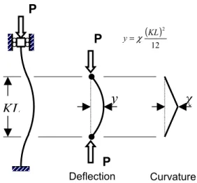
The curvature of the column is assumed to vary linearly from inflection points to mid-height, as shown in Fig. 4, so for any assumed curvature, χ, the mid-height deflection, y, of the column, with effective length KL, can be calculated using:
( )
12
2 KL
y=χ (9)
For each element in the column’s cross-section, the temperature, stress, and strain are assumed to be represented by those at the centroid of the element. The axial strain that causes stress in any element is equal to the sum of the free thermal strain,
( )
εT e, the bending strain,χ e
d , and the overall (average) axial strain, εa, since all elements are subjected to both axial and flexural loads. Thus, for an element on the left-hand side of the column centreline, the axial strain causing stress is calculated from:
( )
εe l =−( )
εT e+εa +heχ (10)where is the distance from the element centroid to the column centerline (refer to Fig. 4). A similar procedure is used on the right-hand side of the column centerline, with the sign of the bending strain is reversed. Once the strain in each element is determined, the stress-strain characteristics at its current temperature, determined using the iterative confinement routine described below in combination with concrete thermomechanical subroutines, can be used to determine the stress. In this manner the elemental force due to each element can be obtained.
e
h
The strains and temperatures in the longitudinal reinforcing bars are assumed to be the same as the concrete elements that the bars lie within. The stress in the steel is determined using thermomechanical subroutines for steel, and the force due to each bar can thus be calculated.
At each instant in time, the overall axial strain in the column is varied until the internal moment at mid-height, due to the contributions of each of the annular elements and reinforcing
bars about the centreline of the column, is equal to the external moment at mid-height, due to the product of applied load and mid-height deflection. The internal moment at mid-height is calculated by summing the contributions of each of the elements, whereas the external moment is calculated as the product of the total vertical force at mid-height, and the horizontal (lateral) deflection of the column at that location. To facilitate the numerical analysis, an initial eccentricity of axial load must be assumed. In the current studies, the initial eccentricity, eo, has
been assumed as eo =15+0.03d , witheo in mm, where d is the column diameter (also in mm).
This value is in accordance with the minimum eccentricity recommended as per Clause 10.12.3.2 of ACI 318 (ACI, 1995) for the design of conventionally-reinforced concrete columns.
By repeating the above procedure for increasing curvatures, load versus mid-height deflection plots for the column can be obtained for a range of times during exposure to fire. From these plots, the maximum load capacity of the column can determined, and a plot of load capacity versus fire exposure time can be developed. The above model can also be used to predict the axial expansion/contraction of circular FRP-confined columns during fire exposure, as well as the pure axial (crushing) strength of short circular FRP-confined columns.
Confinement Modeling at High Temperature
A unique aspect of the numerical model described herein is that it accounts for the beneficial effects of FRP confinement on the strength of FRP-confined reinforced concrete columns exposed to fire. The confinement effect has been incorporated in the analysis using a modified version of the iterative confinement procedure developed by Spolestra and Monti (1999). This specific model was chosen for the current numerical development because it is one of the few available confinement models that can rationally calculate the confining pressure exerted by an FRP wrap for any level of compressive strain in the concrete (Bisby et al., 2003).
Applying the Spolestra and Monti confinement model to the numerical analysis presented herein is complicated by the fact that the mechanical properties of the concrete in the column (required as inputs for the model) are non-uniform over the column cross-section due to material deterioration at increased temperature. Thus, an extension of the model was required to account for the damaging effect of fire on the properties of both the concrete and the FRP wrap.
With the overall axial strain in the concrete assumed, and the temperatures throughout the cross-section known, the maximum unconfined concrete stress and strain for each ring of the column, and the modulus and ultimate tensile strength of the wrap (based on its average temperature) are obtained from thermomechanical subroutines. These mechanical properties are used as inputs for the Spolestra and Monti model, and the confining pressure is determined. The procedure for calculation of the confinement pressure at any instant in time is as follows:
1. The column is discretized into a series of ring elements (refer to Fig. 2). 2. The overall axial strain in the column, εa, is assumed.
3. The confining pressure applied by the wrap, flat, is assumed.
4. The average temperature of the FRP wrap, Twrapi , at time step, i, is calculated using:
1 1 1 M T T i m M m i wrap
∑
= = (11)and the stress-strain characteristics of the wrap at the current temperature are obtained from thermomechanical subroutines.
5. For each ring of the column, the confined concrete strength, fcc' , is obtained, using:
− − + = ' 2.25 1 7.9 ' 2 ' 1.25 ' co lat co lat co cc f f f f f f (12)
where is the compressive strength of the unconfined concrete at the current temperature of the element in question.
'
co
f
6. The confined compressive strength of the element is used, along with the concrete stress-strain curve of Popovics (1973), to determine the current element stress, , at the current strain, c f a ε : r cc c x r r x f f + − ⋅ ⋅ = 1 ' (13) where cc a x εε = , − + = 1 5 ' 1 ' co cc co cc f f ε ε , sec E E E r c c − = , cc cc f E ε ' sec = (14a, b, c, d)
In the above equations Ec is the initial modulus for the unconfined concrete, taken as '
5700 fco (Spolestra and Monti, 1999).
7. The lateral strain, εlat, for each ring element is determined using an equation developed by Spolestra and Monti (1999), which gives dilation as a function of axial strain and concrete stress: c c a c lat f f E β ε ε 2 − = where 5700 500 ' − = co f β (15)
8. The lateral strain in each ring due to thermal expansion, εT, is determined assuming that all elements are free to expand laterally, and the total lateral strain in each concrete ring is calculated by summing the dilation and thermal strains over the cross-section.
9. The overall lateral stain of the column, εtot, is approximated by averaging the lateral strain contributions from each elemental concrete ring over the cross-section:
(
)
1 2 2 1 M M M M m m T lat tot − + =∑
= ε ε ε (16)10. The overall lateral strain is used to determine the strain in the FRP wrap, and hence to update the lateral confinement pressure, which is calculated using a modification to the Spolestra and Monti confinement procedure suggested by Manfredi and Realfonzo (2001):
w tot w w lat d E t f =0.685⋅2 ε (17)
In the above equation, t is the overall thickness of the FRP wrap, is the modulus of the FRP wrap at the current average wrap temperature, and d is the average diameter of the wrap.
w Ew
w
11. The confinement pressure obtained above is used as the new value assumed in step 3, and steps 3 to 10 are repeated until convergence of the confining pressure is achieved.
The confinement model as implemented here essentially assumes that the wrap is unbonded, since it suggests a constant confining pressure at all points in the column cross section. Tests have indicated that, for columns subjected to both axial and flexural loads, a bonded wrap will actually provide a higher level of confinement in the regions of the cross section subjected to compressive flexural strains. The assumption of a constant confining pressure is thus conservative in the current analysis.
Thermomechanical Subroutines
To accurately model the effects of fire on structural members, a detailed knowledge of the thermal and physical properties of the constituent materials is required. In the numerical model presented herein, the variation in thermal and physical properties of the constituent materials with temperature is accounted for by updating the temperatures of constituent materials
in thermomechanical subroutines. These subroutines compute thermal and mechanical properties at the updated temperatures and transfer this information back to the main program.
Subroutines for reinforcing steel and concrete were developed using mathematical relationships that are relatively well established for numerical fire modeling (Lie, 1992). For FRP, the density, thermal conductivity, and specific heat were modeled using data presented by Griffis et al. (1984), and the mechanical properties were modeled using semi-empirical analytical relationships derived by the authors (Bisby, 2003). Only thermal property subroutines describing thermal conductivity and heat capacity were required for the supplementary thermal insulation.
MODEL VALIDATION
Test data are not currently available on the fire behavior of FRP-confined reinforced concrete columns. It is instructive, however, to compare predictions of the model with experimental data from fire endurance tests on conventional reinforced concrete members, such that the model can be used with relative confidence to conduct preliminary qualitative studies investigating the fire behavior of FRP-confined columns. Few test results from fire endurance tests on circular reinforced concrete columns are available in the literature, and to the knowledge of the authors, only two such studies have been performed. Lie and Celikkol (1991) reported the results of two full-scale fire endurance tests on circular spirally-reinforced concrete columns, and Franssen and Dotreppe (2003) reported the results of four full-scale fire endurance tests on tied circular reinforced concrete columns. The Lie and Celikkol (1991) columns were 3810 mm long with a diameter of 356 mm. Their 28-day concrete cylinder compressive strength was 42 MPa, and their longitudinal reinforcement consisted of six 20 mm diameter bars with a yield strength of 414 MPa. The columns were tested with fixed-fixed end conditions. The Franssen and Dotreppe (2003) columns were 2100 mm long with a diameter of 300 mm. Their 28-day
concrete cube compressive strength was 60 MPa, and their longitudinal reinforcement consisted of six 20 mm diameter or six 12 mm diameter bars with yield strengths of 500 MPa. These columns were tested with pinned-pinned end conditions. In both studies the columns were cast using siliceous aggregate concrete. Details of the columns are presented in Table 1.
Prediction of Temperatures
The numerical model presented herein was used to evaluate the fire behavior of the Lie and Celikkol (1991) columns, and a comparison was made between the experimental results and the predictions of the model. Fig. 5 shows experimental and predicted temperatures in the concrete at various depths as a function of fire exposure time. Significant variability is observed in the experimental data, likely due to slight dislocation of the thermocouples in the concrete during concrete pouring operations, and due an incomplete understanding of the variation in material properties with temperature. At a depth of 25 mm, there is generally good agreement between the experimental and predicted temperatures, although the model tends to under-predict temperatures within the first hour of fire exposure. At depths of 64 and 178 mm, the experimental curves are characterized by rapid increases in temperature followed by regions of relatively constant temperature. This behavior is more pronounced at greater depths, and has been attributed by previous authors (Lie and Celikkol, 1991; Lie et al., 1992) to thermally induced moisture migration in the concrete, which is not accounted for in the model. While the model accounts for evaporation of moisture at a temperature of 100ºC, it does not account for its migration toward the centre of the column during heating. Hence, the numerical model tends to under-predict concrete temperatures early in the fire exposure, with closer agreement demonstrated at later stages. It is important to recognize that the late-stage temperatures are
those that play an important role in determining the fire endurance of the columns, and hence the initial discrepancy is not of major concern.
Axial Deformation
Fig. 6 shows the measured and predicted axial deformation of the Lie and Celikkol (1991) columns, as a function of fire exposure time, using an applied axial load of 1431 kN (as was applied during the fire endurance tests). Within the first two hours of fire exposure, the calculated deformation is generally slightly greater than that observed in tests. This could be due to short term creep of the concrete or seating effects not accounted for in the model, both of which would tend to decrease the observed deformation. However, both the maximum deformation and the point of failure are predicted reasonably well by the model. The greatest difference between predicted and measured axial deformation is in the order of 1.5 mm, which is small in comparison to the overall length of the columns (3810 mm). Axial deformation of the members is due to a number of factors, including thermal expansion, load effects, short-term thermally induced creep, and bending, some of which cannot (at this point) be completely accounted for by the model. Nonetheless, the model adequately predicts the overall magnitude of elongation as compared with test data.
Load Capacity
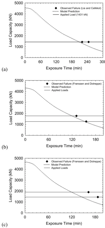
Fig. 7a shows the predicted axial strength of the Lie and Celikkol (1991) columns as a function of fire exposure time, and Figs. 7b and 7c show similar plots for the Franssen and Dotreppe (2003) columns. Also included in Fig. 7 are horizontal lines showing the sustained axial load that was applied to the various columns during fire endurance tests. The fire endurance of the members is defined as the point where load capacity drops below the applied axial load. Fire endurances, as observed in tests, are included as points in Fig. 7. The reader will
note excellent agreement between the model predictions and experimentally observed fire endurance times. Table 1 gives a comparison of predicted and observed fire endurances for all six columns examined. It is evident that the numerical model generally performs well at predicting the fire endurance of conventionally reinforced circular concrete columns, and that it is slightly conservative (from 3% to 16%) for all six columns used in the comparison.
With the above discussion in mind, the model was deemed to satisfactorily predict the fire behavior of circular reinforced concrete columns, although the above comparisons provide no validation of the model for the confining effect of an FRP wrap during fire. Full-scale fire endurance tests on loaded FRP-confined reinforced concrete columns are currently underway. These tests will provide data that can be used to more completely validate the numerical model.
PRELIMINARY MODEL PREDICTIONS
The numerical model can be used to make preliminary predictions and provide insight into the behavior of FRP-confined columns during fire. It was used to predict the behavior in fire of the Lie and Celikkol (1991) columns with four different configurations: the unconfined reinforced concrete column as described in Table 1 (column No. 1 or 2), the same column confined with a single layer of a typical carbon FRP sheet, and the confined column with either a 10 mm or 25 mm thick layer of supplemental insulation applied to the exterior of the FRP wrap. For the purposes of illustration, the insulation is assumed to have a constant thermal conductivity of 0.2 W/m·K and a constant heat capacity of 1360 kJ/m3·K, properties which are equivalent to those of a typical gypsum plaster at room temperature (Buchanan, 2001). The FRP wrap is assumed to have a thickness of 0.76 mm, an ultimate tensile strength of 1510 MPa, and an elastic modulus of 90.2 GPa. Details of the columns used in the preliminary comparative analysis are included in Table 2.
Fig. 8 shows the predicted temperatures at the wrap/concrete interface all four columns analyzed. The effect of supplemental insulation is clearly evident in the predictions, with much lower temperatures predicted at the level of the FRP for the two insulated cases, as should be expected. It has been suggested in the past that satisfactory performance of FRP wrapping systems in fire could be defined as maintenance of the FRP wrap temperature below the GTT of the polymer matrix, the rationale being that the wrap should presumably maintain some effectiveness at temperatures below its GTT. It is likely that such a criterion is highly-conservative, given the life-safety objectives of fire design, and the more holistic structural approach that is preferable. However, it is interesting to consider what the consequences of such a criterion might be.
Most polymer matrices for use in external plating of reinforced concrete structures have GTTs in the range of 65ºC to 150ºC (ACI, 2002). If the GTT is taken to be 100ºC, for the purposes of illustration, then Fig. 8 and Table 2 suggest that, even with a 25 mm thick coating of insulation (with the thermal properties of gypsum plaster) applied to the exterior of the FRP wrap, the fire endurance of the FRP-confined column examined here would only be about 33 minutes, far less than is generally required for concrete columns in conventional structures. This suggests that maintaining the FRP below the GTT will be difficult, if not impossible (for insulation thicknesses that could be used in practice). In any case, the fire endurance of FRP-confined columns should be defined in terms of load carrying capacity during exposure, rather than the temperature at some specific location.
Fig. 9 shows the predicted load carrying capacity of the four columns as a function of fire exposure time. It is evident that the capacity of all four columns decreases with increasing fire exposure. The initial strength of the unconfined column is slightly less than the confined
columns due to the confining effect of the FRP wrap. It is interesting to note that the increase in strength due to FRP wrapping is predicted to be relatively small (only about 4%). This can be explained by considering that the load capacity analysis is essentially a buckling strength analysis, and FRP confinement cannot be expected to significantly increase the modulus of elasticity of the concrete in the column. Hence, the room temperature strength of the columns is increased only slightly by FRP wrapping.
The unconfined column is predicted to fail, at the instant when the load capacity of the column drops below its applied service load, at 164 minutes of fire exposure. The service load has been approximated by back-calculating from the ACI-318 (ACI, 1995) design strength assuming a 1-to-1 live-to-dead load ratio. The FRP-confined column, which has an increased service load as a consequence of its increased design strength due to FRP confinement, is predicted to fail at 117 minutes based on a service load back-calculated from the ultimate design strength predicted by ACI-440.2R-02 (ACI, 2002). Load calculations have been included in the appendix. However, the FRP-confined and insulated columns have much higher fire endurances, even though the effectiveness of the wrap is likely lost in the early stages of fire exposure (when the GTT is exceeded). Thus, thermal insulation, applied to the exterior of the FRP wrap, results in superior fire performance for the FRP-confined column, even if the effectiveness of the FRP wrap is lost early in the fire exposure. This can be explained by considering that concrete and reinforcing steel, unlike FRP, are relatively unaffected by temperatures up to 400ºC. Thus, it is thermal protection of the existing column that contributes to enhanced fire endurance. Of course, full-scale fire resistance tests are required to verify this result and to ensure that any specific insulation used will stay in place during fire. Such tests on FRP-confined and insulated
reinforced concrete columns are currently underway, and the results of this test program will be reported at a later date.
CONCLUSIONS
In this paper, a numerical model was described that can be used to evaluate the endurance of circular FRP-confined reinforced concrete columns to exposure to a standard fire. The model has been validated against data from fire endurance tests on reinforced concrete columns available in the literature, and has been found to agree reasonably well with experimental results. The model was subsequently used to conduct a preliminary numerical investigation of the fire endurance of FRP-confined reinforced concrete columns, and suggests that:
• If the fire endurance of an FRP-confined reinforced concrete column is defined in terms of the temperature at the level of the FRP wrap, then supplemental fire insulation, applied to the exterior of the FRP wrap, is essential to maintain temperatures below prescribed values. The limiting temperatures would likely be the GTT or ignition temperature of the polymer matrix. • It will likely be very difficult, within the practical range of insulation thicknesses, to maintain the confining effectiveness of an FRP wrap during fire. If fire endurance is defined in terms of the load-carrying capacity of the column – as it should be according to current fire endurance testing guidelines (ASTM, 2001) – then the FRP wrap should be considered ineffective during fire. However, supplemental insulation applied to the exterior of the wrap is capable of dramatically improving the fire endurance of the overall column.
APPENDIX I. ACKNOWLEDGEMENTS
The authors are members of the Intelligent Sensing for Innovative Structures Network (ISIS Canada) and wish to acknowledge the support of the Networks of Centres of Excellence Program of the Government of Canada and the Natural Sciences and Engineering Research
Council of Canada. The authors would also like to acknowledge the financial contributions of the National Research Council of Canada and Queen’s University, Canada.
APPENDIX II. REFERENCES
ACI. (2002) “Guide for the design and construction of externally bonded FRP systems for strengthening concrete structures.” ACI 440.2R-02, Farmington Hills, MI.
ACI. (2001) “Guide for the design and construction Concrete Reinforced with FRP Bars.” ACI 440.1R-01, Farmington Hills, MI.
ASTM. (2001) “Standard Methods of Fire Test of Building Construction and Materials.” E 119-01, West Conshohocken, PA.
ACI. (1995) “Building Code Requirements for Structural Concrete.” ACI 318-95, Farmington Hills, MI.
Bisby, L.A. (2003) Fire Behavior of FRP Reinforced or Confined Concrete, Ph.D. Thesis, Dept. Civ. Engrg, Queen’s University, Kingston, ON.
Bisby, L.A., Dent, A.J.S, and Green, M.F. (2003) “A comparison of models for FRP-confined concrete.” Submitted to J. Comp. Constr., 9 pp.
Blontrock, H., Taerwe, L., and Matthys, S. (1999) “Properties of Fiber Reinforced Plastics at Elevated Temperatures with Regard to Fire Resistance of Reinforced Concrete Members.” Fibre Reinforced Polymer Reinforcement for Reinforced Concrete Structures, ACI, Detroit, MI, 43-54. Buchanan, A.H. (2001) Structural Design for Fire Safety, Wiley, New York.
Franssen, J.-M. and Dotreppe, J.-C. (2003) “Fire Tests and Calculation Methods for Circular Concrete Columns.” Fire Tech., 39, 89-97.
Griffis, C.A., Masmura, R.A., & Chang, C.I. (1984) “Thermal response of graphite epoxy composite subjected to rapid heating.” Environmental Effects on Composite Materials, V. 2, Technomic, Lancaster, PA, 245-260.
ISIS. (2001) Strengthening reinforced concrete structures with externally bonded fiber reinforced polymers, Intelligent Sensing for Innovative Structures Canada, Winnipeg, MB.
Katz, A., and Berman, N. (2000) “Modeling the effect of high temperature on the bond of FRP reinforcing bars to concrete.” Cement and Concrete Comp., 22, 433-443.
Kodur, V.K.R., and Baingo, D. (1998) “Fire Resistance of FRP Reinforced Concrete Slabs.” IRC Internal Report No. 758. National Research Council of Canada, Ottawa, ON.
Lie, T.T. (1992) Structural Fire Protection. ASCE Manuals and Reports on Engineering Practice No. 78, New York, NY.
Lie, T.T. and Celikkol, B. (1991) “Method to calculate the fire resistance of circular reinforced concrete columns.” ACI Mat. J., 88(1), 84-91.
Lie, T.T., Chabot, M., and Irwin, R.J. (1992) “Fire Resistance of Circular Hollow Steel Sections Filled with Bar-Reinforced Concrete.” IRC Internal Report No. 636, National Research Council of Canada, Ottawa, ON.
Manfredi, G., and Realfonzo, R. (2001) “Models for concrete confined by fiber composites”. Proc. 5th Annu. Symp. on Fibre-Reinforced-Plastic Reinf. for Concrete Struct., Thomas Telford, London, 865-874.
Popovics, S. (1973) “Numerical approach to the complete stress-strain relation for concrete.” Cement and Conc. Res., 3(5), 583-599.
Sorathia, U., Dapp, T., and Beck, C. (1992) “Fire Performance of Composites.” Mat. Engng.,
Spoelstra, M. R., and Monti, G. (1999) “FRP-confined concrete model.” J. Comp. Constr., 3(3), 143–150.
APPENDIX III. NOTATION
The following are symbols used in this paper: Ag gross cross-sectional area of concrete;
Ast cross-sectional area of steel;
C specific heat;
CE environmental reduction factor for FRP;
d diameter;
h moment lever arm for an element about the column centerline;
E elastic modulus;
eo initial eccentricity;
f’ concrete stress;
f stress;
h moment lever arm for an element about the column centerline;
i time step counter;
K effective length factor;
k thermal conductivity;
L layer thickness;
M1 element counter at the wrap-fire interface;
M2 element counter at the wrap-concrete interface;
m element counter;
Pmax maximum allowable axial load on an FRP-wrapped column;
Q thermal energy (heat);
R radius;
r parameter described by Eqn. 14c;
DL
S service dead load after FRP wrapping;
LL
S service live load after FRP wrapping;
T temperature;
t time;
tf thickness of a single play of FRP wrap;
V volume;
x radial distance ordinate;
y column deflection at mid-height;
β parameter described by Eqn. 15;
∆Q change in thermal energy (heat);
∆t time interval;
ε strain;
κa confinement effectiveness coefficient;
π 3.14159;
ρ density;
ρf FRP reinforcement ratio;
φ strength reduction factor;
(max)
n
P
φ maximum axial design strength of column;
column curvature at mid-height; and
f additional strength reduction coefficient for confined concrete.
Subscripts
a axial;
c in the concrete;
cc of the confined concrete;
co of the unconfined concrete;
e of the element;
fe effective, for the FRP wrap;
fu at ultimate, for the FRP wrap;
in into an element;
l to the left of the column centerline;
lat lateral;
lay of a layer;
out out of an element;
sec secant;
st stored in an element;
surf of the surface;
T thermal;
tot total;
w of an element in the FRP wrap;
wrap of the entire FRP wrap; and
APPENDIX IV. LOAD CALCULATIONS
Fire endurance test loads were calculated in accordance with ASTM E119 (ASTM, 1998). The actual tested properties for the Lie and Celikkol (1991) columns have been used, as an example, in all calculations. Thus, a concrete compressive strength of 42 MPa and a yield strength of 414 MPa in the longitudinal reinforcing steel have been assumed. The maximum design strength, φPn(max), for a spirally-reinforced unwrapped concrete column according to ACI 318 is taken as (Cl. 10.3.5.1):
(
)
[
c g st y st]
n f A A f A P(max) =0.85φ 0.85 ' − + φ (18)where φ is equal to 0.75 for spiral columns, Ag is the gross cross-sectional area of concrete, and
Ast is the area of longitudinal reinforcing steel in compression. Thus, for the current discussion:
( )
[
( ) ( )
(
( )
)
(
)
]
kN 2699 300 6 414 300 6 178 42 85 . 0 75 . 0 85 . 0 2 (max) = ⋅ + − = π φPn (19)The wrap is assumed to have an ultimate tensile strength of 1510 MPa and a thickness of 0.76 mm per layer. The confining pressure provided by an FRP jacket installed around a circular member with a diameter, d, can be found using the ACI 440.2 procedure (Cl. 11.1):
00854 . 0 356 76 . 0 1 4 4 = ⋅ ⋅ = = d ntf f ρ (20)
where n is the number of layers of FRP, tf is the wrap thickness per layer, and d is the column
diameter. The effective ultimate strength of the FRP wrap is taken as the product of the ultimate strength and an environmental reduction coefficient, CE:
MPa 5 . 1283 1510 85 . 0 ⋅ = = = E fu fe C f f (21)
In the above expression, CE is equal to 0.85 for CFRP with an interior conditioned exposure
(ACI, 2002). The confining pressure at ultimate can be determined as (with κa= 1.0 for a circular column): MPa 96 . 10 2 5 . 1283 00854 . 0 0 . 1 2 = ⋅ ⋅ = = a f fe lat f f κ ρ (22)
The confined ultimate strength of the concrete is calculated using:
MPa 2 . 91 25 . 1 2 94 . 7 1 25 . 2 , , , , = − − + = co lat co lat co cc f f f f f f (23)
Finally, the ultimate strength of the FRP-wrapped RC column can thus be determined as:
(
)
[
]
(
)
[
(
) ( )
(
( )
)
(
]
kN 5064 300 6 414 300 6 178 2 . 91 95 . 0 85 . 0 75 . 0 85 . 0 85 . 0 85 . 0 2 ' (max) = ⋅ + − ⋅ = + − = π ψ φ φPn f fcc Ag Ast fyAst)
(24) ACI 440.2 (Cl. 8.2) states that careful consideration should be given to determine reasonable strengthening limits. These limits must be imposed to guard against collapse of the structure should some compete failure of the FRP system occur due to unforeseen circumstances. As such, the existing strength of the structure should satisfy:( )
φRn existing ≥(
1.2SDL +0.85SLL)
new (25)In the above expression,
( )
φRn existing is the existing strength of the member, is the strengthened service dead load, and S is the strengthened service live load.DL
S
LL
Assuming that the factored design load is 50% due to live load and 50% due to dead load, and using the ACI load factors of 1.4 and 1.7 for dead and live loads, respectively, the maximum allowable axial design strength, Pmax, can be calculated for the FRP-wrapped column as follows:
( )
(
)
kN 3977 7 . 1 5 . 0 85 . 0 4 . 1 5 . 0 2 . 1 2699 85 . 0 2 . 1 max max max ⇒ ≤ + ≥ + ≥ P P P S S Rn existing DL LL new φ (26)Thus, with a 1-to-1 dead-to-live load ratio the maximum allowable service load is:
kN 2589 7 . 1 5 . 0 4 . 1 5 . 0 max max = + = P P S (27)
Table 1: Details of columns used for validation of the numerical model No. (1) Diameter (mm) (2) Principal reinforcement (3) Clear cover (mm) (4) Concrete strength (MPa) (5) Steel yield strength (MPa) (6) Applied load (kN) (7) F.E. test (min) (8) F.E. model (min) (9) F.E.model F.E.test (10) 11 356 6 Ø 20 mm 48 42 414 1431 220 209 0.95 21 356 6 Ø 20 mm 48 42 414 1431 245 209 0.85 32 300 6 Ø 12 mm 38 60 500 1260 156 152 0.97 42 300 6 Ø 12 mm 38 60 500 1770 131 119 0.91 52 300 6 Ø 20 mm 38 60 500 1450 187 146 0.78 62 300 6 Ø 20 mm 38 60 500 1900 163 120 0.74 1
test reported by Lie and Celikkol (1991)
2
Table 2: Details of columns used in numerical studies No. (1) FRP wrap details (2) Insulation thickness (mm) (3) Service load1 (kN) (4) Ultimate load1 (kN) (5) Fire endurance2 (min) (6) Fire endurance3 (min) (7) % difference2 vs. unwrapped (8) 1 None 0 mm 1758 2699 4 164 -- 2 1 layer 0 mm 2589 3977 4 117 -29% 3 1 layer 10 mm 2589 3977 27 284 73% 4 1 layer 25 mm 2589 3977 33 >300 >100% 1
refer to the appendix for load calculations
2
based on reaching the critical temperature of the matrix GTT (100ºC) at the FRP/concrete interface
3
Temperature (oC) 0 200 400 600 800 Stren g th (% of initita l) 0 20 40 60 80 100
Concrete (Kodur and Baingo, 1998) Steel (Kodur and Baingo, 1998) FRP (Bisby, 2003)
Figure 1: Variation in tensile strength of concrete, steel, and FRP at elevated temperature
½ ∆xw 1 ∆xw 2 Fire M1 ½ ∆xc ∆xc M1 Rc Wrap Rw m Concrete M2
Figure 2: Discretization of column cross-section for heat transfer analysis
Column Centreline FRP-Concrete Boundary M 1, 1 ∆C M1+2, 1 M1+2, n M1+2, N R Line of Symmetry M2, 1
( ) 12 2 KL y χ P P =
y
KL
Deflection P CurvatureFigure 4: Assumed variation in column curvature and deflection used in load-capacity analysis
Exposure Time (min)
0 60 120 180 240 T e mp er a tur e ( o C) 0 200 400 600 800 1000
Lie and Celikkol - Test 1 Lie and Celikkol - Test 2 Model Predictions 25 mm Depth 64 mm Depth 178 mm Depth
Figure 5: Predicted and observed temperatures at various locations in the columns tested by Lie and Celikkol (1991)
Exposure Time (min)
0 60 120 180 240 Axia l E longa ti o n (mm) 0 2 4 6 8 10
Lie and Celikkol - Test 1 Lie and Celikkol - Test 2 Model Prediction
(a) Exposure Time (min) 0 60 120 180 240 300 L oad Cap a cit y (kN) 0 1000 2000 3000 4000 5000
Observed Failure (Lie and Celikkol) Model Prediction
Applied Load (1431 kN)
(b) Exposure Time (min)
0 60 120 180 Load C apacit y (kN ) 0 1000 2000 3000 4000 5000
Observed Failure (Franssen and Dotreppe) Model Prediction
Applied Loads
(c) Exposure Time (min)
0 60 120 180 L oad Cap a cit y (kN) 0 1000 2000 3000 4000 5000
Observed Failure (Franssen and Dotreppe) Model Prediction
Applied Loads
Figure 7: Predicted and observed load carrying capacity of the validation columns (a) columns No. 1 and 2 tested by Lie and Celikkol (1991)
(b) columns No. 3 and 4 tested by Franssen and Dotreppe (2003) (c) columns No. 5 and 6 tested by Franssen and Dotreppe (2003)
Exposure Time (min) 0 60 120 180 240 300 T e mp er a tur e ( o C) 0 200 400 600 800 1000 ASTM-E119 Fire Unwrapped Wrapped-Uninsulated Wrapped-Insulated 1 Wrapped-Insulated 2
Figure 8: Predicted temperature at the outside surface of the concrete for various column and wrap configurations
Exposure Time (min)
0 60 120 180 240 300 L oad Cap a cit y (kN) 0 1000 2000 3000 4000 5000 6000 Unwrapped Wrapped-Uninsulated Wrapped-Insulated 1 Wrapped-Insulated 2 117min 164 min 284 min Unwrapped Service Load Wrapped Service Load
LIST OF FIGURE CAPTIONS
Figure 1: Variation in tensile strength of concrete, steel, and FRP at elevated temperature Figure 2: Discretization of column cross-section for heat transfer analysis
Figure 3: Discretization of column cross-section for load capacity analysis
Figure 4: Assumed variation in column curvature and deflection used in load-capacity analysis Figure 5: Predicted and observed temperatures at various locations in the columns tested by Lie and Celikkol (1991)
Figure 6: Predicted and observed elongation of columns tested by Lie and Celikkol (1991) Figure 7: Predicted and observed load carrying capacity of the validation columns
(a) columns No. 1 and 2 tested by Lie and Celikkol (1991) (b) columns No. 3 and 4 tested by Franssen and Dotreppe (2003) (c) columns No. 5 and 6 tested by Franssen and Dotreppe (2003)
Figure 8: Predicted temperature at the outside surface of the concrete for various column and wrap configurations
AUTHOR CONTACT INFORMATION
Luke A. Bisby, Ph.D.
Assistant Professor
Department of Civil Engineering Queen’s University
Kingston, Ontario, Canada K7L 3N6
Phone: 613-533-3086 Fax: 613-533-2128
Email: bisby@civil.queensu.ca
Mark F. Green, Ph.D., P.Eng.
Professor
Department of Civil Engineering Queen’s University
Kingston, Ontario, Canada K7L 3N6
Phone: 613-533-2147 Fax: 613-533-2128
Email: greenm@civil.queensu.ca
Venkatesh K.R. Kodur
Senior Research Officer Fire Risk Management Group
Institute for Research in Construction National Research Council of Canada Ottawa, Ontario, Canada
K1A 0R6
Phone: 613-993-9729 Fax: 613-954-0483