HAL Id: hal-03118797
https://hal.archives-ouvertes.fr/hal-03118797
Submitted on 22 Jan 2021
HAL is a multi-disciplinary open access
archive for the deposit and dissemination of
sci-entific research documents, whether they are
pub-lished or not. The documents may come from
teaching and research institutions in France or
abroad, or from public or private research centers.
L’archive ouverte pluridisciplinaire HAL, est
destinée au dépôt et à la diffusion de documents
scientifiques de niveau recherche, publiés ou non,
émanant des établissements d’enseignement et de
recherche français ou étrangers, des laboratoires
publics ou privés.
Facile chemical activation of graphite felt by KMnO4
acidic solution for vanadium redox flow batteries
Ali Hassan, Théodore Tzedakis
To cite this version:
Ali Hassan, Théodore Tzedakis. Facile chemical activation of graphite felt by KMnO4 acidic
so-lution for vanadium redox flow batteries. Applied Surface Science, Elsevier, 2020, 528, pp.146808.
�10.1016/j.apsusc.2020.146808�. �hal-03118797�
Any correspondence concerning this service should be sent
to the repository administrator:
tech-oatao@listes-diff.inp-toulouse.fr
This is an author’s version published in:
http://oatao.univ-toulouse.fr/27300
To cite this version: Hassan, Ali and Tzedakis, Theodore
Facile chemical activation of graphite felt by KMnO4 acidic
solution for vanadium redox flow batteries. (2020) Applied
Surface Science, 528. 146808. ISSN 0169-4332
Official URL
DOI :
https://doi.org/10.1016/j.apsusc.2020.146808
Open Archive Toulouse Archive Ouverte
OATAO is an open access repository that collects the work of Toulouse
researchers and makes it freely available over the web where possible
Facile chemical activation of graphite felt by KMn0
4acidic solution for
vanadium redox flow batteries
Ali Hassan
*
, Theodore Tzedakis
*
Laboratoire de Génie Chimique, UMR CNRS 5503, Université de Toulouse, UT-III-Paul Sabatier, 118 Route de Narbonne, F-31062 Toulouse, France
A BST R ACT
Keywords:
Graphite felt chemical activation
Vanadium redox flow batteries
Charge-discharge cycles GF surface free energy
Intrinsic heterogeneous electronic transfer constant
The activation method is proposed to enhance the electroactivity of the graphite felt (GF), to be used as positive half-cell electrode for vanadium redox flow batteries (VRFBs). Two following activation approaches are used 1) functionalization of electrode surface by the chemical treatment with acidic solution of the KMnO4 and 2) deposition of KMnO4 derived particles on the surface of GF. The intrinsic heterogeneous electronic transfer
constant (k0) ofv<VJ ;v<rvJ system is enhanced by 2.6 and 6.1 times for the oxidation cv<1VJ-+ yCVJ) and reduction
cvcvJ -+ yOVJ) reactions, respectively. The performed electrolysis in the half-cell shows the improved reversibility
of the electrode. The treated electrode is also evaluated on the stack level by using 100 cm2 GF in each elec trolytic section of the battery, by charge and discharge cycles. The results clearly indicate the lowering of anodic and cathodic overvoltage, i.e. the average charging voltage decreases from 1.86 V to 1.76 V, while the obtained voltage during discharge increases from the 0.59 V to 0.8 V. The proposed activation method is operationally simple; and activated electrode shows the promising performance as positive half-cell electrode in VRFBs.
1. Introduction
Renewable energy has been getting prime importance since few decades because of diminishing conventional power resources and en vironmental challenges. But the intermittent nature of these resources, limits their viability and raise the question of their sustainability on commercial scale. Effective energy storage systems are important to shear off the gap between the supply and demand; and to align it with the Joad requirements. Redox flow batteries (RFBs) can successfully overcome this practical limitation because of their underlying char acteristics of detached energy and power density. There is the ad vantage of flow batteries over conventional lead-acid batteries, that the energy is stored in the electrolyte, outside of stack. So, the capacity of flow batteries depends on concentration and the volume of electrolyte. Due to this, the scale up of battery is easy; as it requires just to alter the volume of electrolyte, without changing the stack.
Different redox couples (Fe/Cr, V /Br, Zn/Ce, bromine/poly sulphide) with wide potential gap, have been investigated for the flow batteries [1-5]. For large scale energy storage applications, the elec trolyte stability for long time is very importance; but using different redox couple in catholyte and anolyte leads to the cross contamination of the electrolyte. In addition to that, it also causes the self-discharge of the flow cell. This problem can be minimized by employing the same metal ions in both compartment of the flow battery, such as in the case
• Corresponding authors.
E-mail address: hassan@chimie.ups-tlse.fr (A. Hassan).
of al! vanadium redox flow batteries (VRFBs) [6-9] The vanadium element exits in four different valencies "v00, ycno, ycrvi, ycvJ,,_ The
idea of using vanadium in both half cells of flow battery was first floated by the Prof. Skyllas Kazacos [10]. The primary redox reactions in the positive and negative half-cell are represented by the eq. (1) and (2), respectively. The standard overall cell voltage is 1.26 V.
Positive electrode: VO{
+
zH++
e- a= vo2++
H20E0(Vo2+/VOt)= l.00VvsSHE; (1) Negative electrode: V3+ + e- a= vz+E0(V2+/V3+) = -0.26VvsSHE; (2)
These redox reactions are taking place on electrodes; and hence, the power density of the flow cell depends on the active surface area of the electrodes and its electro-kinetic activity . So, the selection for the electrode material is critical in the optimization of the vanadium redox flow battery stack. It is also important, because the stack is contributing approximately 30% of the total cost of VRFBs [11]. Many carbon electrode materials have been investigated so far, to be used as elec trode for the vanadium redox flow batteries i-e carbon paper, glassy carbon, graphene oxide, graphite fibers, graphite felt, carbon felt and multiwalled carbon nanotubes etc. [12-14]. The PAN based graphite felt with 3D fibrous structure, is potential candidate as electrode ma terial for the VRFBs, because of its significant surface area [15]; in
A. Hassan and T. Tzedakis
addition to that, it is very stable in acidic conditions. However, it shows very poor kinetic reversibility against vanadium redox flow couples
[16].Different strategies are reported in literature to enhance the electrocatalytic activity of the graphite felt by electrochemical, che mical and thermal activation methods, but most often they are com plicated, prolong and involved complicated experimental setups. The purpose of these methods is to increase the available surface area and fabricate different functional groups on surface. The increase in the active surface area helps the battery to achieve higher current operating currents; while the different functional groups of the oxygen and ni trogen act as catalyst, resulted into the lowering of the activation overpotential [17-26]. Different metals and their oxides (Pt, ZrO2, Nb2O5, CeO2, Pd, PbO2, Au etc.) also facilitate to overcome the kinetic limitation of the carbon electrodes towards the vanadium redox flow couples[27-31]. But most often they are expensive; and their me chanical stability is also questionable in the flow conditions of acid electrolyte. Meta! oxides also accelerate the secondary reactions of the 02 and H2 formation, which narrows down the operating voltage window of the battery[32-33]. The negative half-cell redox reaction is relatively faster and more reversible than positive half-cell reaction, as it involves one electron transfer step (V2+ s=V3+); while the positive half-cell reaction(Vot s= vo2+) undertake one additional step of oxygen transfer [34-36]
Robert [37] discussed that the strong oxidizers like KMnO4 can be used to activate the carbon-based electrode by thermal and electro chemical treatment for flow batteries. The patent content is very gen eral and qualitative; moreover, the expected effects, at the least in the positive electrode of vanadium redox flow battery, were not indicated. In this study, two different approaches were investigated to activate the GF, to use as positive half-cell electrode in VRFBs. In first approach, the GF was heated at 140 "C for 2 h in 0.01 M KMnO4 acidic solution, under non-reflux conditions. The method modified the surface chemistry and morphology of GF successfully, by fabricating the oxygenal groups on its surface and incorporate more roughness on it. The activated GF showed enhanced electro-kinetic activity, as positive half-cell electrode. In another method, the KMnO4 derived particles were fabricated on the GF, but it did not show any catalytic activity towards positive half-cell redox reaction. It is important to note, that Wang et al. [38] fabricated the MnO2 nanosheets array-decorated carbon paper by KMnO4 and it showed improved electroactivity as negative half-cell electrode in VRFBs.
2. Experimental
2.1. Materials
Ali the chemicals were of analytical grade and not required further processing. Vanadium (IV) oxide sulfate hydrate VOSO4·xH2O and po tassium permanganate KMnO4 were provided by the VWR interna tional, France. The nafion membrane (N-424) was purchased from the Ion power Inc. USA. The Sulphuric acid (95-97%) was purchased from the Sigma-Aldrich Co. France. Poly acrylonitrile (PAN) based graphite felt (GF) of 3 mm thickness, and platinum wire of 0.125 mm thickness (99.95%) were provided by Goodfellow Cambridge Ltd. France.
2.2. Electrode preparation
In this study, GF was activated by adopting two different ap proaches. First approach is concerned to change the surface chemistry and roughness of the GF, by heating it in the KMnO4 acidic solution and named as class-1 for further reference. Second approach is concerned to fabricate residuals potassium permanganate particles on the surface of the GF, to analyze their effect against vo2+ /VO2 + reaction and de scribed as Class - 2 in further text. Both are discussed in detail, as following.
2.2.1. Glass -1 approach
The purpose of this treatment is to functionalize the surface of the GF by harnessing the oxidizing power of acidic KMnO4 solution. For this, the commercial GF was thoroughly rinsed with the distilled water and used as reference (untreated-GF). After, it was pretreated at 400 "C for 2 h in muffle furnace to had better solution interaction while che mical activation ( 400 "C -2h-GF). The annealed GF was heated at 140 "C for 2 h in 0.01 M KMnO4 + 3 M H2SO4 solution, under non reflux conditions (KMnO4-140 "C-2 h-GF). Tuen the GF was washed with hot and cold distilled water several times to remove any kind of the acidic and KMnO4 residues.
2.2.2. Glass -2 approach
During this operation, two different GF samples were prepared to investigate the following two possibilities:
1) To fabricate the thermally cracked KMnO4 particles on the GF and check their electroactivity against VO2 + /VO
2 + redox system
(KMnO4-600 "C-N2-GF).
2) To deposit the KMnO4 particles (without chemical decomposi tion) on the GF and investigate their catalytic effect against the VO2 + / VO2 + redox system (KMnO4-400 "C-air-GF).
First sample was prepared by dipping the GF in the beaker, con taining 0.01 M KMnO4 + 3 M H2SO4 solution , and then put this beaker in the oven at 80 "C until ail the solution was evaporated. The obtained dry GF, covered with residual permanganate was heated at 600 "C in the nitrogenous environment for 90 min, to thermally decompose the KMnO4 compounds and to have GF surface covered with cracked KMnO4 particles (KMnO4-600 "C-N2-GF).
Second sample was prepared by adopting the similar procedure as above, except 1) the operating temperature was fixed for oven at 400 "C and 2) the presence of the air in the oven. The purpose of heating at 400 "C was to attach the residual permanganate on the GF surface. As the objective here, was not to thermally crack the KMnO4, so the temperature chosen was lower ( 400 'C) than the previous one (600 'C). Both samples were washed thoroughly with the distilled water con taining few drops of H2SO4
3. Electrode characterization
3.1. Electrocatalytic evaluations
The electrode electrocatalytic activity was evaluated at transient state by cyclic voltammetry (CV) in classical three electrode cell. The 1 cm2
piece of the GF was precisely eut and subject to CV at the fol lowing experimental parameters; scan rate: 10 mV s-1; in 0.05 M vo2+ + 2 M H2SO4 electrolyte; between the potential ratio of O V to 1.6 V in unstirred conditions. The platinum foi! of 3 cm2
and saturated calomel electrode (SCE) were used as counter and reference electrode, respec tively.
Linear sweep voltammetry (LSV) curves were plotted with the precisely eut graphite felt of 1.5 x 1.5 cm2 at the scan rate of 1 mV s-1 with stirring rate of 350 rpm. To study the kinetics of the of vcrvJ to vM reaction on GF, the experiment was started from open circuit potential (OCP) towards the anodic direction, in solution of 0.5 M vo2+ + 3 M H2SO4. The anodic scan was stopped, when system approached 1.2 V. The reverse scan was performed towards cathodic direction, in the electrolyte of 0.47 < VO2cto < 0.49 + 3 M H2SO4, to evaluate the performance of GF for vM to vovJ reaction. The VO
2 + solution used for
the reverse scan was obtained by the electrolysis of the 0.5 M vo2+ + 3 M H2SO4 solution, in the half cell.
3.2. Electrode surface characterization
The changes occurred in the surface chemistry of the GF were analyzed by the Fourier transform infrared spectroscopy (FTIR) on thermo Nicolet 6700 (Thermo Fisher Scientific, USA). The untreated
A. Hassan and T. Tzedakis
Fig. 1. a) The vanadium redox flow battery having electrochemical reactor with 10 cm x 10 cm electrodes (1), accompanied by posolyte (2 + ) and negolyte storage tanks (2-) of 1 L capacity; with two pumps (3) for continuons flow of the electrolyte; b) The individual components of electrochemical reactor of VRFBs, comprising of steel plate, teflon plate, gaskets, membrane, positive and negative half-cell electrolytic sections.
80 40
--~·
==
� �1E
0 -40 0.0a)
2- -
4oo•c
-lh-G•· 3 --KMnO4-140°C-2h-GF 0.4 0.8 1.2E
(GFISCE)V 1.6 80 40;:;--:;;
� -,:::-
0 -40 0.0b
)
Untre11ted-GF - -KMnO,-400' -Air-CF 5 KMnO4-<iOO 'C-0.4 2-GF 0.8 1.2E
(GF/SCEJV 1.6 Fig. 2. a) The CV of the class-1 and b) class - 2 electrodes; in 0.05 M VO2 + + 2 M H2SO4 ; at scan rate of 10 m V s -1, with precisely eut 1 cm2 of GF as working electrode, 3 cm2 platinum foi! as counter electrode and saturated calomel electrode (SCE) as reference electrode.
and treated GF was grinded to prepare samples for the FTIR analysis. 2.5 mg of the grinded powder was mixed with the 250 mg of KBr and subjected to the 10 ton of pressure to fonn a disk of 13 mm diameter. The modification of surface morphology and roughness of the electrode was analyzed at the acceleration voltage of the 10 KV, by the scanning electron microscopy (SEM) on the Phenom XL (Thenno Fisher scien tific, USA).
3.3. Half-cell and full stack evaluation
The H-shaped divided lab scale reactor (shown in the inset of
Fig. 8), was used to perform the charge discharge cycles. Initially po sitive half-cell was constituted by 0.5 M vo2 + + 3 M H2S04, while the
negative half-cell contained the 3 M H2S04• The GF (2.25 cm2) and platinum foil (3 cm2) were used as the positive and negative electrodes, respectively. The saturated calomel electrode (SCE), placed in a lugging capillary, was introduced to follow the potential of the positive elec trode. The full battery scale charge-discharge cycles of VRFBs were performed in filter press reactor, having 100 cm2 of GF electrode in positive and negative electrolytic section, as shown in Fig. 1. Two storage tanks containing the anolyte and catholyte, each having the capacity of 1 L, were coupled to the electrochemical plug flow reactor. The constant flow of electrolyte was maintained through the reactor during charge and discharge process. To avoid the re-oxidation of V2 +
by oxygen, the supply of Argon was continuously provided in the ne gative storage tank. The individual components of the electrochemical
A. Hassan and T. Tzedakis
reactor are shown in Fig. l,b. As current collector, the grid of platinized titanium is inserted into the part of the GF that is outside of the elec trolytic section.
4. Results and discussion
4.1. Cyclic voltammetry analysis
The CV curves were plotted to evaluate the improvement in the electrode after activations, in the 0.05 M vo2+ + 2 M H2SO4 elec trolyte; between the potential ratio of O V to 1.6 V, at the scan rate of 10 mV s-1• The scan started in the anodic direction from the open
circuit potential (OCP) until 1.6 V, then it revered back towards cathodic direction until O V, as shown in Fig. 2.
In the analysis of the CV curves, the following performance para meters are compared; 1- anodic peak current (la), 2- cathodic peak current (le) 3- anodic to cathodic peak current ratio (la / le), 4- dif ference between the anodic and cathodic peak potentials (J.Ea/c = Ea -EJ. The individual peak currents correspond to the available surface area for the reactions, so any increment of the current observed, could be linked to the increase of available surface area of the electrode. The reversibility of the reactions on the electrode improves with the de crease of la / le and J.E a/c , and vice versa [39].
Fig. 2,a shows the comparison of the voltammograms of the class -1 treated electrodes i-e untreated-GF, 400 °C -2h-GF and KMnO4
-140 °C-2 h-GF. The peak observed around 1.1 V- 1.3 V shows the oxi dation of the VO2 + to VO2 + , while peak in the reverse scan shows the reduction of the VO2 + to VO2 +. In the case of untreated electrode, the reverse scan does not have the well-defined peak, indicating the poor reversibility of the electrode. All the performance parameters (la, le, la/
Ie, 11Ea;c) are improved due to the prescribed activation procedure, as summarized in the table 1. The increment of - 35% is observed in the magnitude of peak currents and peak potential difference is minimized by 300 mV. The improvement of the electrochemical activity of the GF is due to the oxygenal functional groups and roughness, that is fabri cated on surface because of the chemical treatment. The oxygenal groups act as the catalytic sites for the vo2+ /VO2 + redox reaction. The surface roughness increases the available surface area for positive half cell reaction and reflected in the increase of the anodic (IJ and cathodic Uc) currents.
Fig. 2,b shows the voltammograms of the class-2 treaded electrodes, in which the KMnO4 particle are adsorbed on the electrode surface. Four peaks are observed in the CV, two in anodic directions and two in cathodic section. Peaks at 1.1 V/1.4 V and 0.4 V/0.6 V are the signais of the oxidations of VO2 + and reduction of VO2 +, respectively. The ad ditional peaks at 0.8 V /1.3 V and 1.5 V /1.6 V is due to the reduction and oxidation of KMnO4 derived species, respectively. Following con clusions could be drawn from these CV observations of class-2 elec trodes; 1) The residual KMnO4 and ail the compounds resulting from its reduction are strongly adsorbed on the surface, as the 10th cycle of the CV has the huge signal of their reduction and oxidation 2) The residual KMnO4 does not exhibit any catalytic behavior against the vo2+ /VO2 + redox couple; and in addition to that, these particles are getting addi tional power to oxidize and reduce back on the surface. 3) There is still little increase in the peak current of vo2+ /VO2 + reaction in compar ison with the untreated electrode, certainly because of the increase in
Table 1
Comparative results of the performance parameters of class- 1 electrodes. The results are extracted from Fig. 2,a voltammograms.
GF samples 1. (mA) [, (mA) 1.11, '1Ea1, = Ea -E, (V)
Untreated-GF 46.9 21.7 2.16 0.99
400 °C -2h-GF 52.5 33.25 1.57 0.77
KMnO4-l40 °C-2 h-GF 63.1 48.03 1.31 0.70
Applied Swface Science 528 (2020) 146808 1500 1000
---
500..
e
� 0 -500 -1000,
I 0.6 --Untreated-GF - --KMnO4°140 °C-2h-GF,
; ; I ; I ;,
;,
0.8 1.0 E( GF!SCE) (V) I , I,
1.2Fig. 3. LSV curves of the untreated-GF and KMnO4-140 °C-2 h-GF with 2.25 cm2 geometrical area; at r = 1 mV s-1, with stirring rate 350 rpm; counter electrode = Pt 3 cm2; Reference electrode = SCE; anolyte initial solution: 0.5 M vo2+ + 3 M H2SO4; catholyte initial solution = 0.47 < VO2dv!J < 0.49 + 3 M H2SO4.
the surface area of the GF .
So, the CV analysis concluded that the class-1 GF electrode, che mically activated by an acidic KMnO4 solution (KMnO4-140 °C-2 h-GF)
exhibits enhanced electrocatalytic activity against VO2 + /VO2 + redox reaction. On the other end, the class-2 GF electrodes having residual KMnO4 particles (and derived adducts) on their surfaces, do not show any improvement against positive half- cell reaction, and will not be discussed further in the text, except in the SEM images section.
4.2. Linear sweep voltammetry (LSV) for k0 calculations
Linear sweep voltammetry was used to investigate the electro-ki netic parameters of vo2+ a=VO2 + reaction on 'untreated-GF' and 'KMnO4-140 °C-2 h-GF', as shown in Fig. 3. A fresh solution containing 0.5 M vo2+ + 3 M H2SO4 was used to plot the anodic curves, while the solution obtained after electrooxidation of initial solution, was used to register the cathodic curves. The curves clearly show that the kinetics of the vo2+ /VO
2 + reaction is improved by the activation procedure. The electronic transfer limited region ofLSV curve (0.7 < Eœ;nv;scE < 1.17) is considered for the calculations of the kinetic parameters (k0, a and fJ), by using simple form of the Butler Valmer Law (Eq. (3)) and the results are summarized in the table 2. The k0 value of the anodic reaction in
creases almost three folds (1.7-+ 4.14 µm s-1), while for the cathodic reaction, this enhancement is 6 times (0.9 --> 5.6 µm s-1).
I _ -nFSk·c bulkexp ( +a or - {3)n'F
RT 7J
Where: 7J = the overvoltage; n
Table 2
(3)
electron exchange number;
Comparative data of kinetic parameters concerning redox system VO2 + /VO2 + on untreated-GF and KMnOr140 °C-2 h-GF, calculated by logarithmic analysis of the LSV curves in Fig. 3.
GF electrodes Reaction involved a J3 k0 (µm s-1)
Untreated-GF vo2+-vo
2+ 0.1 1.7
KMnO4-140 °C-2 h-GF 0.17 4.14
Untreated-GF vo2 +- vo2+ 0.1 0.92
A. Hassan and T. Tzedakis
'\ .. -.t_
'•.,t ... , ___ ---
:1500 2000 2500 3000 3500 4000
Wanenumber (cm·')
Fig. 4. FTIR spectra of the untreated-GF and the KMnO4-140 °C-2 h-GF.
F
=
faradie constant; S=
surface area; k0=
intrinsie heterogeneous electronie transfer constant; a and f3 = anodie and cathodie electronie transfer coefficients, respectively.4.3. FITR and SEM analysis
The surface of the electrode was characterized by FTIR analysis, before and after treatment. The obtained spectra is compared in Fig. 4. The peak at the 3443 cm - l corresponds to the stretching vibration of -OH group [ 40], while the peak at the 1628 cm - l is assigned to the hydroxyl group in enol -C
=
C-OH [41]. The intensity of both peaks increased after activation of the GF, thus indieating the increase in the concentration of oxygenal groups on the surface of electrode. These groups are supposed to act as catalytic sites towards the positive half cell reaction, as the vo2 + s= V02
+ reaction involves the oxygen transfer; and presence of the oxygen groups on the GF could possibly assist this transfer.
The changes occurred in the surface morphology of the GF were also characterized by the SEM analysis. Fig. 5 show the comparative images of Untreated-GF (a,b,c) and KMnO4-140 °C-2 h-GF (d,e,D, at different
magnifications. Activation method did not cause any physieal damage in the overall fibrous structure, as no fragments of broken fibers are visible in Fig. 5, d. The surface of
the untreated GF is relatively smooth with some scratches; these scratches becomes sharper after activation. The sharp scratches and higher roughness provide more available surface area for the positive half-cell reactions. This observation is also consistent with the CV
results, in whieh peak current enhanced on the KMnO4-140 °C-2 h-GF
and it is directly linked with increase of active surface area.
The SEM images of the class-2 treated electrode is shown in Fig. 6
(a,b,c). It is evident that KMn04 particles are successfully adsorbed on the GF surface. It was discussed with detail in the cyclie voltammetry section 4.1, that these particles are practically not contributing towards the vanadium reactions.
4.4. Swface free energy quantification of electrode
The better electrode-electrolyte interaction is one of the important parameters towards the kineties of the redox reactions. The surface of the graphite felt is intrinsieally hydrophobie and requires activation for the improvement of its wettability. The proposed chemieal activation successfully enhanced the wettability of the electrode. To observe this electrode-electrolyte interaction, 5 µL droplet of the 0.5 M vo2 + + 3 M H2SO4 was placed on untreated-GF and KMnO4-140
°
C-2 h-GF. The droplet retained on the surface of the untreated GF, while it penetrates immediately in the 3D fibrous structure of treated GF, as shown in Fig. 7
a, d. This observation clearly indieates, that the activation successfully increases the surface energy of the electrode that resulted into the improvement of its wettability.
Improvement in the wettability can be quantified by surface energy calculations. For this, the semi quantitative approach is used, men tioned somewhere else [42]. Eq. (4) and (5) are representative equa tions for these calculations. The electrode-electrolyte contact angles of two different liquids of known dispersive and polar components are required. The yJF o.s (slope) and y!JF 0·5(intercept) are obtained by the plot of(YL(l + cose))/(2(yf:}°5
) vs (ri/rf:)05•
(4) (5)
where; YaF, YbF yf}F represents the total, polar and dispersive surface free energy of electrode, respectively; And Yv Yi , yf:, indieates the total, polar and dispersive surface free energy of liquid. e represents the electrode-electrolyte contact angle.
In this study, water and glycerol were used for the quantification of the surface energy of the GF. The untreated and treated GF was crushed and spread over the hydrophobie tape. After, the contact angles of the glycerol and water droplets (10 µL each) were precisely measured on this approximate fiat surface. The contact angle of the water droplet decreased from 98.5°
to 44.9°
(Fig. 7 b,e), while the glycerol angle was changed from 93.5°
to 34.3°
(Fig. 7 c,D. The results of the surface free
A. Hassan and T. Tzedakis
Fig. 6. SEM images of the KMn04-600 °C-N2-GF at different magnifications (class 2 electrode).
Fig 7. Wettability evaluation by placing 5 µL droplet of 0.5 M vo2+ + 3 M H2S04 on untreated GF(a) and KMn04-140 °C-2 h-GF(d); The 10 µL droplet of water on
untreated GF (b) and KMn04-140 °C-2 h-GF (e); 10 µL droplet of glycerol on untreated GF (c) and KMn04-140 °C-2 h-GF (f). energy calculations are summarized in table 3
Due to activation of electrode, the surface free energy is increased from 13.9 mN/m to 53.29 mN/m. This increment is responsible for the better wettability and electrode-electrolyte interaction.
4.5. Charge-Discharge cycles
To evaluate the performance of activated GF against vo2+ :;::t V0 2 +
reaction, charge-discharge cycles were performed in following two different reactors, 1) H shaped divided electrochemical cell and 2) filter
press divided electrochemical reactor. The electrolysis was carried out
under galvanostatic conditions at constant current density.
4. 5.1. H shaped divided electrochemical cell
The electrolysis was initially performed in H type divided cell, as shown in the inset of Fig. 8. The posolyte was constituted by 0.5 M vo2+ + 3 M H
2S04 , while the negolyte was an aqueous solution of 3 M sulfuric acid. Operating in a half-cell enables to check the perfor mance of the positive electrode without having any interference from the reactions involved at the negative electrode. The posolyte was mechanically stirred at 350 rpm, while the stirring conditions in ne golyte was indigenously established by the H2 bubbles, produced during protons electro-reduction.
The electrolysis was performed in anodic direction at constant current density of 667 Am -2, enabling the oxidation of yOVJ to V(V). The electrolysis was carried out until the working electrode voltage
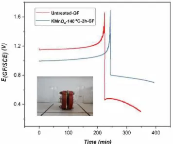
A. Hassan and T. Tzedakis 1.6 ----Untreated-GF KMnO.·140 °C-2h-GF S 1.2 � � � 0.8 tu 0.4 0 100 200 Time (min) 300 400
Fig. 8. Evolution of the working electrode potential of untreated-GF and KMnO4-140 °C-2 h-GF, during charge- discharge electrolysis, performed in a H
shaped divided electrochemical cell (inset). Nafion membrane is used for se paration of electrolytic compartrnents. posolyte: 0.5 M vo2+ + 3 M H
2SO4;
negolyte: 3 M H2SO4; SGF: 2.25 cm2
Table 3
The results of surface free energy calculations of untreated GF and KMnO
4-140 °C-2 h-GF. Electrode Untreated GF KMn04-140 °C-2 h-GF 6.5 30.25 23.04 7.4 Yap(mN/m) 13.9 53.29
approached 1.65 V. Then the cathodic current density of 667 A m -2 was applied to convert back vCVJ to vcrvi_ The voltage evolution of char ge-discharge electrolysis of untreated-GF and KMnO4-140 °C-2 h-GF is shown in Fig. 8. Due to the activation of GF, the average charging voltage decreased from 1.18 V to 1.04 V and average discharge voltage increased from 0.42 V to 0.75 V. These observations confirm the posi tive effect of the treatment on the electrode, as the decrease of the
2.4
a)
- - "7 Untreate<f-GF 2.2 --; KMn04-140'C-2h-GF .� 2.0 I,,
/ a, I,,
/ I / / / / 0 1.8 :::. 1.6 1.4 0 5 10 15 20 25 time (h)overvoltage translates to the increase in energy and voltage efficiency. Three consecutive charge-discharge cycles were performed to check the durability of electrode performance; and the electrode maintained the performance during these cycles.
4.5.2. Filter press divided electrochemical reactor
The filter press electrochemical reactor was used to perform the charge-<lischarge cycles under galvanostatic mode, to evaluate the performance of electrode on the full-scale redox flow battery. Both, posolyte and the negolyte were initially constituted by 0.5 M vo2+ +
3 M H2S04. The initial volume of the posolyte (500 ml) was double than the negolyte to compensate the difference in the electrolysis duration, induced by the electron's ratio cvrv - vov)l(VIV - VII) = 1/2. The electrolysis was carried out under a constant current of 0.5 A (SGF = 100 cm2), until the cell voltage reached 2 V; then the applied current decreased to 0.35 A, and the electrolysis pursued again until the cell voltage approached 2 V. This sequence was repeated in two addi tional stages at 0.2 A and 0.1 A respectively, until the 80% state of charge (SOC) of battery was achieved. After it, half volume of the po solyte was removed, and subsequently charge-discharge cycle was performed under galvanostatic conditions by using untreated-GF and
KMnO4-140 °C-2 h-GF electrodes. The constant current density of 50 A m -2 was applied during charge discharge cycles. 2 V was set as the upper voltage limit, because the solvent tends to oxidize at higher voltages and can be observable in the form of 02 evolution. On the other end, the release of H2 is also possible in the negative electrode compartment if the applied current is higher than the total limiting current of the successive reduction of vo2+ to v2+.
The cell voltage evolution during electrolysis for electrolyte pre paration, is shown in the Fig. 9, a. Only the first and last voltage point is plotted at each current. The cell voltage is lower in the case of treated electrode than the untreated electrode, during ail the operation. The observation indicates the enhanced electrocatalytic behavior of the activated electrode.
Cell voltage curves during charge-discharge cycle are shown in
Fig. 9, b. Due to activation of electrode, the average charging voltage decreased from 1.86 V (untreated) to 1.76 V (treated) and average discharging voltage increased from 0.59 V (untreated) to 0.80 V (treated) . At a current density of 50 A m-2, there is an improvement of
20% and 13% in energy and voltage efficiency (VE), respectively. This observation reveals that, in comparison with untreated electrode, the
2.4
b)
2.0 � 1,6 � 0 1.2:::.
0.8 0.4 0.0 0 500 1000 - Untreated-GF ---+-KMn04-140 °C-2h-GF 1500 Q (mA.h) 2000 2500Fig. 9. a) cell evolution during the electrolyte preparation by using untreated GF and KMnO4-140 °C-2 h-GF; b) charge discharge cycles of untreated GF and KMnO
A. Hassan and T. Tzedakis
activated electrode requires lower power for charging; and obtained power during discharge is higher. Also, the duration of the charging and discharging is prolonged, resulted in the higher conversions.
5. Conclusion
The proposed chemical method successfully activated the GF, to be used as positive electrode in the VRFBs. In the CV analysis , -35% enhancement was observed in the peak current of V02 + .= V0
2 + redox reaction. The electronic transfer kinetic constant (k.0) of charge and discharge reactions in positive half-cell, were enhanced by 2.6 and 6.1 times, respectively. The surface free energy calculations by contact angle measurements reveals that the electrode-electrolyte affinity was improved after activation that plays an important role in the surface catalysis. The surface oxygenal groups, integrated during activation process was expectedly catalyzing the positive half-cell reactions. Moreover, the available surface area for the reactions was enhanced because the activation made the surface rough and grooved. The acti vated GF showed the promising results during charge-discharge cycles, conducted at the following two different reactors 1) H-shaped divided
electrochemical ceU and 2) filter press divided electrochemical reactor. The
prescribed activation process is operationally very easy, as it does not require any complicated procedures .
6. Financials
This work was supported by ANR (L'Agence nationale de la re cherche, France) and the Campus France.
CRediT authorship contribution statement
Ali Hassan: Conceptualization, Methodology, Investigation,
Writing - original draft, Formal analysis, Validation. Theodore
Tzedakis: Conceptualization, Methodology, Supervision, Writing - re
view & editing, Validation.
Declaration of Competing Interest
The authors declare that they have no known competing financial interests or personal relationships that could have appeared to influ ence the work reported in this paper.
Acknowledgments
The authors would like to acknowledge Ms. Brigitte Dustou for providing technical support regarding the filter press divided electro chemical reactor. We are also very grateful to Dr. Fabien Chauvet for his technical support for the contact angle measurements.
References
[l] A.Z. Weber, M.M. Mench, J.P. Meyers, P.N. Ross, J.T. Gostick, Q. Liu, Redox flow batteries: A review, J. Appl. Electrochem. 41 (2011) 1137-1164, https://doi.org/ 10.1007 /sl0800-0l l-0348-2.
[2] Y.K. Zeng, T.S. Zhao, L. An, X.L. Zhou, L. Wei, A comparative study of ail-vanadium and iron-chromium redox flow batteries for large-scale energy storage, J. Power Sources. 300 (2015) 438-443, https://doi.org/10.1016/j.jpowsour.2015.09.100. [3] H. Zhou, H. Zhang, P. Zhao, B. Yi, A comparative study of carbon felt and activated
carbon based electrodes for sodium polysulfide/bromine redox flow battery, Electrochim. Acta. 51 (2006) 6304--6312, https:/ /doi.org/10.1016/j.electacta. 2006.03.106.
[ 4] H. Vafiadis, M. Skyllas-Kazacos, Evaluation of membranes for the nove! vanadium bromine redox flow cell, J. Memb. Sei. 279 (2006) 394-402, https:/ /doi.org/10. 1016/j.memsci.2005.12.028.
[5] D.J. Park, K.S. Jeon, C.H. Ryu, G.J. Hwang, Performance of the ail-vanadium redox flow battery stack, J. Ind. Eng. Chem. 45 (2017) 387-390, https://doi.org/10. 1016/j.jiec.2016.10.007.
[6] L. Cao, A. Kronander, A. Tang, D.W. Wang, M. Skyllas-Kazacos, Membrane per meability rates of vanadium ions and their effects on temperature variation in va nadium redox batteries, Energies. 9 (2016), https:/ /doi.org/10.3390/en9121058.
[7] C. Choi, S. Kim, R. Kim, Y. Choi, S. Kim, H. young Jung, J.H. Yang, H.T. Kim, A review of vanadium electrolytes for vanadium redox flow batteries, Renew. Sustain. Energy Rev. 69 (2017) 263-274. doi:10.1016/j.rser.2016.11.188.
[8] M. Skyllas-Kazacos, L. Cao, M. Kazacos, N. Kausar, A. Mousa, Vanadium Electrolyte Studies for the Vanadium Redox Battery-A Review, ChemSusChem. 9 (2016) 1521-1543, https://doi.org/10.1002/cssc.201600102.
[9] L. Joerissen, J. Garche, C. Fabjan, G. Tomazic, Possible use of vanadium redox-flow batteries for energy storage in small grids and stand-alone photovoltaic systems, J. Power Sources. 127 (2004) 9S-104, https://doi.org/10.1016/j.jpowsour.2003.09. 066.
[10] M. Skyllas-Kazacos, All-Wanadium Redox Battery, United States Pat. (1988). [11] M. Zhang, M. Moore, J.S. Watson, T.A. Zawodzinski, R.M. Counce, Capital Cost
Sensitivity Analysis of an Ail-Vanadium Redox-Flow Battery, J. Electrochem. Soc. 159 (2012) All83-All88, https://doi.org/10.1149/2.041208jes.
[12] A. Di Blasi, O. Di Blasi, N. Briguglio, A.S. Aricà, D. Sebastian, M.J. Lâzaro, G. Monforte, V. Antonucci, Investigation of several graphite-based electrodes for vanadium redox flow cell, J. Power Sources. 227 (2013) 15-23, https:/ /doi.org/10. 1016/j.jpowsour.2012.10.098.
[13] C. Flox, J. Rubio-Garcia, R. Nafria, R. Zamani, M. Skoumal, T. Andreu, J. Arbiol, A. Cabot, J.R. Morante, Active nano-CuPt3 electrocatalyst supported on graphene for enhancing reactions at the cathode in ail-vanadium redox flow batteries, Carbon N. Y. 50 (2012) 2372-2374, https://doi.org/10.1016/j.carbon.2012.01.060. [14] A. Bourke, M.A. Miller, R.P. Lynch, X. Gao, J. Landon, J.S. Wainright, R.F. Savinell,
D.N. Buckley, Electrode Kinetics of Vanadium Flow Batteries: Contrasting Responses of V O -V rn and V ,v -V v to Electrochemical Pretreatroent of Carbon, J. Electrochem. Soc. 163 (2016) A5097-A5105, https://doi.org/10.1149/2. 013160ljes.
[15] R. Schweiss, T. Oelsner, F. Diirfler, A. Davydov, S. Wiihner, A. Hirschvogel, Recent lnsights into Carbon Felt Electrodes for Redox, Flow Batteries (2011).
[16] K.J. Kim, S.W. Lee, T. Yim, J.G. Kim, J.W. Choi, J.H. Kim, M.S. Park, Y.J. Kim, A new strategy for integrating abondant oxygen functional groups into carbon felt electrode for vanadium redox flow batteries, Sei. Rep. 4 (2014) 1--6, https://doi. org/10.1038/srep06906.
[17] A. Hassan, T. Tzedakis, Enhancement of the electrochemical activity of a com mercial graphite felt for vanadium redox flow battery (VRFB), by chemical treat ment with acidic solution of K2Cr2O7, J. Energy Storage. 26 (2019) 100967, , https:/ /doi.org/10.1016/j.est.2019. l 00967.
[18] P. Mazur, J. Mrlîk, J. Benes, J. Pocedic, J. Vrâna, J. Dundâlek, J. Kosek, Performance evaluation of thermally treated graphite felt electrodes for vanadium redox flow battery and their four-point single cell characterization, J. Power Sources. 380 (2018) 105-114, https://doi.org/10.1016/j.jpowsour.2018.01.079. [19] T. Liu, X. Li, C. Xu, H. Zhang, Activated Carbon Fiber Paper Based Electrodes with
High Electrocatalytic Activity for Vanadium Flow Batteries with Improved Power Density, ACS Appl. Mater. Interfaces. 9 (2017) 4626-4633, https://doi.org/10. 1021/acsami.6b14478.
[20] Z. He, Y. Jiang, H. Zhou, G. Cheng, W. Meng, L. Wang, L. Dai, Graphite felt elec trode modified by square wave potential pulse for vanadium redox flow battery, !nt. J. Energy Res. 41 (2017) 439-447, https://doi.org/10.1002/er.3626.
[21] Y.C. Chang, J.Y. Chen, D.M. Kabtamu, G.Y. Lin, N.Y. Hsu, Y.S. Chou, H.J. Wei, C.H. Wang, High efficiency of CO2-activated graphite felt as electrode for vanadium redox flow battery application, J. Power Sources. 364 (2017) 1-8, https://doi.org/ 10.1016/j.jpowsour.2017.07.103.
[22] J. Kim, H. Lim, J.Y. Jyoung, E.S. Lee, J.S. Yi, D. Lee, Effects of Doping Methods and Kinetic Relevance of N and O Atomic Co-Functionalization on Carbon Electrode for V(IV)/V(V) Redox Reactions in Vanadium Redox Flow Battery, Electrochim. Acta. 245 (2017) 724-733, https:/ /doi.org/10.1016/j.electacta.2017.06.008. [23] Z. He, Y. Jiang, W. Meng, F. Jiang, H. Zhou, Y. Li, J. Zhu, L. Wang, L. Dai, HF/
H2O2treated graphite felt as the positive electrode for vanadium redox flow bat tery, Appl. Surf. Sei. 423 (2017) 111-118, https://doi.org/10.1016/j.apsusc.2017. 06.154.
[24] J. Kim, H. Lim, J.Y. Jyoung, E.S. Lee, J.S. Yi, D. Lee, High electrocatalytic perfor mance of N and O atomic co-functionalized carbon electrodes for vanadium redox flow battery, Carbon N. Y. 111 (2017) 592-601, https://doi.org/10.1016/j.carbon. 2016.10.043.
[25] D.M. Kabtamu, J.Y. Chen, Y.C. Chang, C.H. Wang, Water-activated graphite felt as a high-performance electrode for vanadium redox flow batteries, J. Power Sources. 341 (2017) 270-279, https://doi.org/10.1016/j.jpowsour.2016.12.004. [26] X.L. Zhou, Y.K. Zeng, X.B. Zhu, L. Wei, T.S. Zhao, A high-performance dual-scale
porous electrode for vanadium redox flow batteries, J. Power Sources. 325 (2016) 329-336, https://doi.org/10.1016/j.jpowsour.2016.06.048.
[27] B. Sun, M. Skyllas-Kazakos, Chemical modification and electrochemical behaviour of graphite fibre in acidic vanadium solution, Electrochim. Acta. 36 (1991) 513-517, https://doi.org/10.1016/0013-4686(91)85135-T.
[28] H. Zhou, Y. Shen, J. Xi, X. Qiu, L. Chen, ZrO2-Nanoparticle-Modified Graphite Felt: Bifunctional Effects on Vanadium Flow Batteries, ACS Appl. Mater. Interfaces. 8 (2016) 15369-15378, https://doi.org/10.1021/acsami.6b03761.
[29] B. Li, M. Gu, Z. Nie, X. Wei, C. Wang, V. Sprenkle, W. Wang, Nanorod niobium oxide as powerful catalysts for an ail vanadium redox flow battery, Nano Lett. 14 (2014) 15S-165, https:/ / doi.org/10.1021/nl40367 4a.
[30] H. Zhou, J. Xi, Z. Li, Z. Zhang, L. Yu, L. Liu, X. Qiu, L. Chen, CeO2 decorated graphite felt as a high-performance electrode for vanadium redox flow batteries, RSC Adv. 4 (2014) 61912-61918, https://doi.org/10.1039/c4ral2339e. [31] X. Wu, H. Xu, L. Lu, H. Zhao, J. Fu, Y. Shen, P. Xu, Y. Dong, PbO2-modified graphite
felt as the positive electrode for an ail-vanadium redox flow battery, J. Power Sources. 250 (2014) 274-278, https://doi.org/10.1016/j.jpowsour.2013.11.021. [32] A.A. Shah, H. Al-Fetlawi, F.C. Walsh, Dynamic modelling of hydrogen evolution
A. Hassan and T. Tzedakis
effects in the ail-vanadium redox flow battery, Electrochim. Acta. 55 (2010) 1125-1139, https:/ /doi.org/10.1016/j.electacta.2009.10.022.
[33] H. Al-Fetlawi, A.A. Shah, F.C. Walsh, Modelling the effects of oxygen evolution in the ail-vanadium redox flow battery, Electrochim. Acta. 55 (2010) 3192-3205, https://doi.org/10.1016/j.electacta.2009.12.085.
[34] M.H. Chakrabarti, R.A.W. Dryfe, E.P.L. Roberts, Evaluation of electrolytes for redox flow battery applications, Electrochim. Acta. 52 (2007) 2189-2195, https://doi. org/10.1016/j.electacta.2006.08.052.
[35] M. Gattrell, J. Park, B. MacDougall, J. Apte, S. McCarthy, C.W. Wu, Study of the Mechanism of the Vanadium 4 + /5 + Redox Reaction in Acidic Solutions, J. Electrochem. Soc. 151 (2004) Al 23, https:/ /doi.org/10.1149/1.1630594. [36] K.J. Kim, M.-S. Park, Y.-J. Kim, J.H. Kim, S.X. Dou, M. Skyllas-Kazacos, A tech
nology review of electrodes and reaction mechanisms in vanadium redox flow batteries, J. Mater. Chem. A. 3 (2015) 16913-16933, https://doi.org/10.1039/ C5TA02613J.
[37] I. Bureau, Wo 2016/164017, (2016).
[38] Y. Jiang, X. Feng, G. Cheng, Y. I.i, C. I.i, Z. He, J. Zhu, W. Meng, H. Zhou, L. Dai,
L. Wang, Electrocatalytic activity of MnO2 nanosheet array-decorated carbon paper as superior negative electrode for vanadium redox flow batteries, Electrochim. Acta. 322 (2019) 134754,, https://doi.org/10.1016/j.electacta.2019.134754. [39] Z. Gonzâlez, C. Flox, C. Blanco, M. Granda, J.R. Morante, R. Menéndez,
R. Santamaria, Outstanding electrochemical performance of a graphene-modified graphite felt for vanadium redox flow battery application, J. Power Sources. 338 (2017) 155-162, https://doi.org/10.1016/j.jpowsour.2016.10.069.
[ 40] X. Wu, H. Xu, P. Xu, Y. Shen, L. Lu, J. Shi, J. Fu, H. Zhao, Microwave-treated graphite felt as the positive electrode for ail-vanadium redox flow battery, J. Power Sources. 263 (2014) 104-109, https://doi.org/10.1016/j.jpowsour.2014.04.035. [ 41] C. Gao, N. Wang, S. Peng, S. Liu, Y. Lei, X. Liang, S. Zeng, H. Zi, Influence of
Fenton's reagent treatment on electrochemical properties of graphite felt for ail vanadium redox flow battery, Electrochim. Acta. 88 (2013) 193-202, https:/ /doi. org/10.1016/j.electacta.2012.10.021.
[42] V.G. Papadakis, Estimation of Estimation of, J. Appl. Polym. Sei. 13 (1969) 1741-1747.