READ THESE TERMS AND CONDITIONS CAREFULLY BEFORE USING THIS WEBSITE.
https://nrc-publications.canada.ca/eng/copyright
Vous avez des questions? Nous pouvons vous aider. Pour communiquer directement avec un auteur, consultez la première page de la revue dans laquelle son article a été publié afin de trouver ses coordonnées. Si vous n’arrivez pas à les repérer, communiquez avec nous à PublicationsArchive-ArchivesPublications@nrc-cnrc.gc.ca.
Questions? Contact the NRC Publications Archive team at
PublicationsArchive-ArchivesPublications@nrc-cnrc.gc.ca. If you wish to email the authors directly, please see the first page of the publication for their contact information.
NRC Publications Archive
Archives des publications du CNRC
This publication could be one of several versions: author’s original, accepted manuscript or the publisher’s version. / La version de cette publication peut être l’une des suivantes : la version prépublication de l’auteur, la version acceptée du manuscrit ou la version de l’éditeur.
Access and use of this website and the material on it are subject to the Terms and Conditions set forth at
A Non-destructive method to measure the airflow resistance of jet
engine nacelles
Nightingale, T. R. T.; Tinianow, B.
https://publications-cnrc.canada.ca/fra/droits
L’accès à ce site Web et l’utilisation de son contenu sont assujettis aux conditions présentées dans le site LISEZ CES CONDITIONS ATTENTIVEMENT AVANT D’UTILISER CE SITE WEB.
NRC Publications Record / Notice d'Archives des publications de CNRC:
https://nrc-publications.canada.ca/eng/view/object/?id=81182639-1b0b-4d44-8e47-c190b97caff5 https://publications-cnrc.canada.ca/fra/voir/objet/?id=81182639-1b0b-4d44-8e47-c190b97caff5
A Non-destructive method to measure the airflow
resistance of jet engine nacelles
Nightingale, T.R.T.; Tinianow, B.
NRCC-47680
A version of this document is published in / Une version de ce document se trouve dans: International Congress on Acoustics, Seattle, WA., June 20-25, 1998, pp. 1899-1900
A Non-Destructive Method to Measure the Airflow Resistance of Jet Engine Nacelles
T.R.T. Nightingale*, Brandon Tinianow†
* Institute for Research in Construction, National Research Council, Ottawa, Ontario, Canada K1A OR6 † Johns Manville Technical Center, 10100 West Ute Ave., Littleton Colorado, USA 80127
Abstract: A method using a modified ASTM E1050 impedance tube is shown to provide a non-destructive method to measure the airflow resistance of nacelle components. The results agree with the traditional ASTM C522 test method. Theory is presented for the prediction of the total resistance and reactance of nacelles based on measurable physical parameters.
INTRODUCTION
As a noise control measure to reduce inlet fan noise of jet engines, the nacelles are often equipped with a thin resistive wire mesh placed over a honeycomb structure. Historically there has been a problem using non-destructive methods, the airflow resistance of repaired or replacement nacelle parts for the purpose of demonstrating OEM compliance. ASTM C522 is the traditional airflow resistance test method and is destructive since it requires a sample be cut from the specimen and fit into an apparatus where the flow velocity due to a constant pressure drop can be measured. This paper presents a non-destructive test method and summarizes the associated theory to describe the impedance of the nacelle.
SPECIMEN DESCRIPTION AND THEORY
Typically a nacelle has a honeycomb core with a rigid plate on one side and a perforated plate on the other. This creates a series of resonant cavities as shown in Figure 1. The cavities do not offer resistance but do offer significant reactance associated with the mass of the air volume. The impedance of the cavity, Zcav, is given by1,
( )
(
L c)
i
Zcav =− cot ω / (1)
where L is the depth of the cavity, c is the speed of sound and ω is angular frequency. The presented resistance and reactance values are normalized to ρc.
The perforated plate has a hole diameter and spacing such that there is significant open area, typically about 40%, with several holes to each honeycomb cell. There is a small resistive component associated with the shear resistance through the holes. The air mass contained in the holes introduces a reactance that is usually small compared to that of the honeycomb cavity. The impedance of the perforated plate is given by,
10 2 , 8 8 2 1 2 〉 ′ + + ′ = ν ω σ νω σ ω σ νω d for cd t c t i cd t Z p p p plate (2)
where ν is the kinematic viscosity (0.15 in CGS units), σp is the fractional open area of the plate and t′ is the
effective plate thickness which includes end corrections and can be approximated by t′=t+d, where t is the actual plate thickness and d is the hole diameter.
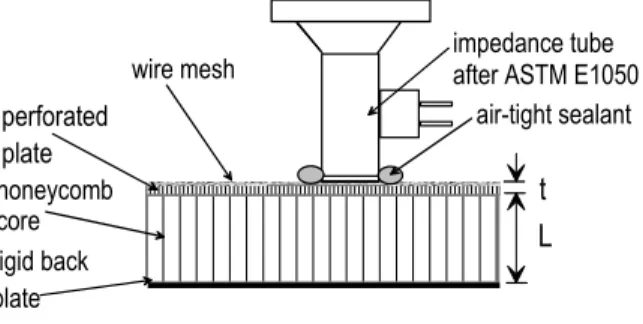
honeycomb core perforated plate rigid back plate
wire mesh impedance tubeafter ASTM E1050 air-tight sealant
L t
Figure 1: Sketch showing the nacelle and the impedance
tube.
Adhering the wire mesh to the perforated plate reduces the effective area of the mesh by a factor of σp.
Thus, the effective impedance of the wire mesh will by Zm =θm /σ p where θm is the mesh resistance. The resistance
to oscillatory airflow through the bonded mesh will be largely independent of frequency until the thickness of the viscous boundary layer is greater than the width of the effective orifice between adjacent strands. The frequency, fb,
at which the resistance will increase with increasing frequency is given by,
2 o b d f
π
ν
= , woof warp m o N Nd =
σ
,σ
m=
1
−
N
warpd
warpN
woofd
woof (3, 4, 5) where do is the effective width of the orifice between strands of wire, Nwarp is the number of warp strands per unitlength, Nwoof is the number of woof strands per unit length and σm is the fraction open area of the mesh given in
Often the resistance at a specific flow rate is required to assess the non-linear characteristics of the assembly resistance. Unfortunately, the particle velocity can not be measured directly but it can be computed from the measured impedance, Zt, when
the root mean square sound pressure, Prms, is known,
-1.0 -0.5 0.0 0.5 1.0 1.5 800 1000 1250 1600 2000 2500 3150 4000 Frequency, Hz Norm al iz ed I m pedance Resistance at 0.3 m/s flow velocity Resistance at 2.7 m/s flow velocity Reactance at 0.3 m/s flow velocity
Figure 3: Measured (solid lines) and predicted (dashed lines)
resistance of a specimen at two flow rates, 0.03 and 0.27 m/s, and the reactance at 0.03 m/s.
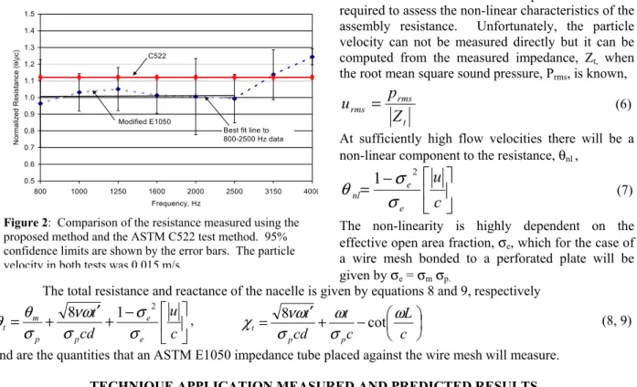
0.5 0.6 0.7 0.8 0.9 1.0 1.1 1.2 1.3 1.4 1.5 800 1000 1250 1600 2000 2500 3150 4000 Frequency, Hz Norm al iz ed Resi st ance ( θ / ρ c) C522 Modified E1050
Best fit line to 800-2500 Hz data
Figure 2: Comparison of the resistance measured using the
proposed method and the ASTM C522 test method. 95% confidence limits are shown by the error bars. The particle velocity in both tests was 0.015 m/s.
t rms rms
Z
p
u
=
(6) At sufficiently high flow velocities there will be a non-linear component to the resistance, θnl ,
−
=
c
u
e e nlσ
σ
θ
1
2 (7)The non-linearity is highly dependent on the effective open area fraction, σe, which for the case of
a wire mesh bonded to a perforated plate will be given by σe = σmσp.
The total resistance and reactance of the nacelle is given by equations 8 and 9, respectively
− + ′ + = c u cd t e e p p m t
σ
σ
σ
νω
σ
θ
θ
8 1 2 , − + ′ = c L c t cd t p p tω
σ
ω
σ
νω
χ
8 cot (8, 9)and are the quantities that an ASTM E1050 impedance tube placed against the wire mesh will measure. TECHNIQUE APPLICATION MEASURED AND PREDICTED RESULTS
The impedance of the nacelle was measured at nine points using a modified ASTM E1050 impedance tube as shown in Figure 1. The average measured resistance and reactance are shown in Figure 2. The measured resistance is independent of frequency below about 2500 Hz, while above this frequency there is a sharp increase in the resistance with increasing frequency. Equation 3 predicts that above 2600 Hz the resistance will cease to be independent of frequency. The y intercept of the best-fit line through the resistance data, 500—2500 Hz, is 1.01 ρc and should be representative of the steady airflow resistance measured using the ASTM C522 test method.
The airflow resistance of nine samples cut from the same nacelle were measured in accordance with ASTM C522 and are shown in Figure 2 as a straight line, 1.12 ρc with a 95% confidence limit of 0.02 ρc. The proposed non-destructive test method for measuring airflow resistance agrees with ASTM C522 test method within experimental error.
Equations 6, 7, 8 and 9 were used to predict the resistance and reactance of a nacelle at two flow velocities 0.03 and 0.27 m/s. The measured and predicted resistance shown in Figure 3 are in good agreement for frequencies less than fb; the range
where the resistance model is applicable. Measured and predicted values for the reactance agree within the experimental uncertainty at most frequencies.
The proposed method provides a non-destructive method to measure the airflow resistance of rigid backed locally reacting absorbers such as jet engine nacelles.
REFERENCES