HAL Id: hal-01338169
https://hal.archives-ouvertes.fr/hal-01338169
Submitted on 28 Jun 2016
HAL is a multi-disciplinary open access
archive for the deposit and dissemination of
sci-entific research documents, whether they are
pub-lished or not. The documents may come from
teaching and research institutions in France or
abroad, or from public or private research centers.
L’archive ouverte pluridisciplinaire HAL, est
destinée au dépôt et à la diffusion de documents
scientifiques de niveau recherche, publiés ou non,
émanant des établissements d’enseignement et de
recherche français ou étrangers, des laboratoires
publics ou privés.
Pressure drop and axial dispersion in industrial
millistructured heat exchange reactors
Maxime Moreau, Nathalie Di Miceli Raimondi, Nathalie Le Sauze, Michel
Cabassud, Christophe Gourdon
To cite this version:
Maxime Moreau, Nathalie Di Miceli Raimondi, Nathalie Le Sauze, Michel Cabassud, Christophe
Gourdon.
Pressure drop and axial dispersion in industrial millistructured heat exchange
reac-tors. Chemical Engineering and Processing: Process Intensification, Elsevier, 2015, 95, pp.54-62.
�10.1016/j.cep.2015.05.009�. �hal-01338169�
O
pen
A
rchive
T
OULOUSE
A
rchive
O
uverte (
OATAO
)
OATAO is an open access repository that collects the work of Toulouse researchers and
makes it freely available over the web where possible.
This is an author-deposited version published in :
http://oatao.univ-toulouse.fr/
Eprints ID : 15850
To link to this article : DOI : 10.1016/j.cep.2015.05.009
URL :
http://dx.doi.org/10.1016/j.cep.2015.05.009
To cite this version :
Moreau, Maxime and Di Miceli Raimondi,
Nathalie and Le Sauze, Nathalie and Cabassud, Michel and
Gourdon, Christophe Pressure drop and axial dispersion in
industrial millistructured heat exchange reactors. (2015) Chemical
Engineering and Processing: Process Intensification, vol. 95. pp.
54-62. ISSN 0255-2701
Any correspondence concerning this service should be sent to the repository
administrator:
[email protected]
Pressure
drop
and
axial
dispersion
in
industrial
millistructured
heat
exchange
reactors
Maxime
Moreau
a,b,
Nathalie
Di
Miceli
Raimondi
a,b,*
,
Nathalie
Le
Sauze
a,b,
Michel
Cabassud
a,b,
Christophe
Gourdon
a,baUniversitédeToulouse,INP,UPS,LGC(LaboratoiredeGénieChimique),4alléeEmileMonso,F-31432Toulouse,Cedex04France bCNRS,LGC(LaboratoiredeGénieChimique),F-31432Toulouse,Cedex04France
Keywords:
Heatexchangereactors Pressuredrop Axialdispersion Modelling
ABSTRACT
Hydrodynamic characterizationby meansof pressure drop and residence time distribution (RTD) experimentsisperformedinthreemillistructuredheatexchangereactors:twoCorningreactors(further referredtoasCorningHPandCorningRT)andaChartreactor.Pressuredropismeasuredfordifferent flowratesandfluids.FanningfrictionfactoristhencalculatedanditsevolutionversusReynoldsnumber isplottedforeachreactor,showingtheinfluenceofthegeometricalcharacteristicsofthereactorsonthis parameter.FromRTDexperiments,axialdispersioncoefficientsthatallowcalculatingPécletnumbersare identifiedbysolvingtheconvection-dispersionequation.Theresultshighlightplugflowbehaviorof thesereactorsfortherangeofflowratesstudied.PécletnumberinCorningHPremainsconstantinthe rangeofReynoldsnumberstudied.Itsspecificpatternisdesignedtogeneratemixingstructuresthat allowhomogenizationofthetraceroverthecross-section.Itexplainstheplugflowbehaviorofthis reactorevenatlowReynoldsnumberbutgenerateshighpressuredrop.PécletnumberinCorningRTand ChartShimTec1increaseswithReynoldsnumber.Thisevolutionisencounteredforstraightcircular
pipesinturbulentregimeandconfirmsthepressuredropanalysis.
1.Introduction
The need to develop safer, more effective and less energy
consuming processes while respecting environmental
require-mentscausedsinceafewyearstheinterestoftheindustryforthe
intensifiedtechnologies.Inthiscontext,heatexchangereactorsare
promising technologies [1]. Indeed it is difficult to control
temperatureinbatchorsemi-batchreactorswhenreactionsare
highly exothermic. Heat exchange reactors may offer a better
thermalcontrolofthereactionsincreasingsafetyandselectivity
while reducing by-products generation. Continuous
millistruc-turedheatexchangereactorsprovideheattransferattheclosestof
thereaction.Theycombinetheadvantagesofmillireactors(fast
mixing,reactivevolumeconfinement)andcompactheat
exchang-ers(hightransferareaandlargematerialmassperunitofreactive
volume).
However, the miniaturization of the devices leads to low
Reynoldsnumberfortheprocessfluid.Toavoidpurelaminarflow,
instabilitieshavetobegeneratedformixingandtransferissues.
Thereforemillistructureddevicesaregenerallycharacterizedbya
complexgeometry of theprocess channelsto promotemixing,
providing specific hydrodynamicbehaviors notably in terms of
pressure dropand Residence TimeDistribution (RTD). Pressure
dropisakeyparametertodesignaprocesssincethecostofthe
pumpsdrivingthefluidthroughtheinstallationisgenerallyagreat
partofthewholecapitalcost.RTDgivespreciousinformationon
thehydrodynamics of the reactorand particularlyon theaxial
dispersion generated. Axial dispersion is responsible of the
spreading of the reactants and the products along the device
which can lead to selectivity and conversion issues. This
hydrodynamicparametermustthus bedeterminedtocorrectly
modelthereaction[2].
The aim of this study is to provide and analyze the
hydrodynamicbehaviorof threeindustrial millistructured
reac-tors:twoCorningfluidicmodulesandaChartreactor.Elgueetal.
[3] demonstrated the performances of these devices for the
implementationofachemicalreaction.Theauthorscarriedouta
two-phaseesterificationandobservedhigherconversionwiththe
intensifiedmillireactorsthaninbatchconditions.Brauneetal.[4]
*Correspondingauthor.Tel.:+33562258920;fax.:+33562258891.
E-mailaddresses:[email protected](M.Moreau),
[email protected](N.DiMiceliRaimondi),
[email protected](N.LeSauze),[email protected]
(M.Cabassud),[email protected](C.Gourdon).
thenBuissonetal.[5]alsodemonstratedtheefficiencyofmass
transfer in Corning mixing module by performing selective
reactions.PressuredropandresidencetimedistributioninCorning
reactorshavealreadybeeninvestigated[6,7]andresidencetime
distribution have also been studied in Chart ShimTec1 based
technologybyCantu-Perezet al.[8].However, theexperiments
werecarriedoutwithwaterforpressuredropmeasurementsand
generic correlations are missing toestimate thehydrodynamic
behaviorusingquantitativeparameters.
In thepresentwork,pressuredropandRTDexperimentsare
carriedout.Theyareanalyzedinordertosuggestcorrelationsfor
the estimation of dimensionless numbers characteristic of the
hydrodynamics of reactors such as Fanning friction factor and
Pécletnumber.Theimpactofthegeometryofthethreedeviceson
thepressuredropandtheRTDresultsisalsodiscussed.Thefirst
part of this paper presents the reactors design and the
experimentalsetup.Thepressuredropresultsarepresentedina
secondpart.Then,theRTDexperimentsandthemethodologyto
identifythePécletnumberaredescribed.Theresultsarecompared
tomodelsavailableinliterature.
2.Experimentalmethod
2.1.Descriptionofthereactors
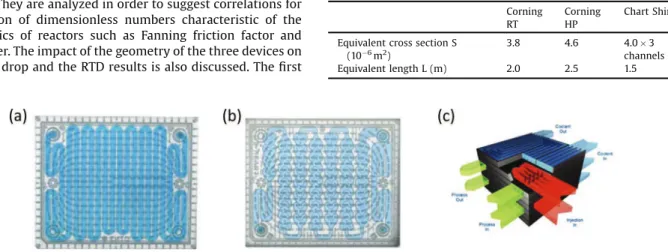
ThedevicestestedaretwoCorningfluidicmodulesG1basedon
theCorningAdvanced-FlowTMtechnology[9]andaChartreactor
basedontheShimTec1technology[10](Fig.1).
Corningmodulesaremadeofthreeglassparts.ThefirstCorning
module (hereinafter called Corning RT for Residence Time) is
composedofoneplatecarvedbyasinglerectangularchannelwith
180!bends.Thesecondmodule(hereinaftercalledCorningHPfor
HeartPattern)isbasedonaHeartPatterndesigned togenerate
mixing structures (51 hearts by plate). Each process plate is
combined with two utility plates that allow to control the
temperatureofthereaction.Thesemodulescanbeusedinseries
to form a complete reactor. The Chart ShimTec1 reactor is
composed of thin plates (also called shims) that include the
channelsofthereactor.Theyarebonded togethertocreatethe
wholestructure.Itiscomposedofthreeparallelprocesschannels.
Thereactorcanbefedbyautilityfluidforheatexchangepurpose.
Thesethreereactorsaredesignedforspecificapplications.Corning
RTismadetopre-heatreactantsbeforeareactionplateortoadd
residencetimeattheendofthesetup.CorningHPislikelyusedfor
two-phase reactions that need intensified mass transfer. Chart
ShimTec1 reactoris designed to producelow pressure dropto
performreactionswithviscousfluids.Theircharacteristic
dimen-sionsaregiveninTable1.Itisdifficulttoestimatethelengthof
CorningHPreactorsinceitssectionisnotconstant.However,the
RTDresultsareusedtoidentifytheequivalentcrosssectionand
length of the reactor. Indeed, these parameters are fitted by
comparingtheshapesoftheexperimentalandcalculatedoutlet
RTDcurvesandtheexperimentalandtheoreticalresidencetimes
(seeAppendixA).Nevertheless,eveniftheseequivalent
character-isticsarenotperfectlyreliable,theydonotaffecttheidentification
ofhydrodynamicbehaviorsasfunctionofthereactorgeometry.For
theChartShimTec1reactor,theequivalentlengthistheaverage
lengthofthe3channels.FortheRTDexperiments,itisconsidered
thattheoutputRTDcurvescanbedecomposedintothreedistinct
curvesrepresentingthepathofthetracerinthethreechannelsof
Nomenclature
c Concentrationoftracer(molm"3)
Dax Axialdispersioncoefficient(m2s"1)
Dh Hydraulicdiameterofthetube(m)
Dm Molecular diffusion coefficient of tracer in solvent
(m2s"1)
E Distributionfunction(s"1)
f Fanningfrictionfactor(")
J Numberofstirredtanks(")
L Lengthofthereactor(m)
P Perimeterofthecrosssection(m)
Pe Pécletnumber(")
Q Flowrate(m3s"1)
Reh HydraulicReynoldsnumber(")
Re ffiffipS SquaresectionReynoldsnumber(")
S Crosssectionofthechannel(m2)
s Minimizationfunction(mol2sm"6)
t Time(s)
tr,exp Experimentalresidencetime(s)
u0 Averagevelocity(ms"1)
V Volume(m3)
x Longitudinalcoordinate(m)
Greekletters
m
Dynamicviscosity(Pa.s)r
Density(kgm"3)D
P Pressuredrop(Pa)Subscripts
calc Calculated
exp Experimental
in Inletofthereactor
out Outletofthereactor
square Squaresection
Fig.1.Millistructuredreactors:(a)CorningRT,(b)CorningHPand(c)ChartShimTec1
[9,10]. Table1 Reactorsdimensions. Corning RT Corning HP ChartShimTec1 EquivalentcrosssectionS
(10"6m2)
3.8 4.6 4.0$3
channels
differentlength.However,itisassumedthatthetracer
concentra-tionattheentranceofeachchannelisthesameastheaverage
velocityand theaxial dispersioncoefficientcharacterizingeach
channel.
2.2.Experimentalsetup
TheexperimentalsetupisillustratedonFig.2.Itiscomposedof
an external gearpump connectedto a feedingtank.A by-pass
systemallowsabettercontroloftheflowrate.AT-shapeinjectoris
usedtoinjectthetracerwithasyringerightbeforetheinletofthe
reactortocarryouttheRTDexperiments.Theoutletofthereactor
islinkedtoastoragetank.ACoriolis-effectflowmetermeasures
the mass flow rate and the density of the process fluid. A
Rosemountdifferentialpressuretransducerconnectedtotheinlet
andtheoutletofthereactorisusedtomeasurethepressuredrop
generated.UVsensorsmeasuretheabsorbanceofthefluidatthe
inletandtheoutletofthereactortofollowtheconcentrationofthe
tracerasafunctionoftime.
2.3.Pressuredropmeasurement
Thepressuredropismeasuredfordifferentflowrates.Water
(
m
=1cP,r
=1000kgm"3)isusedforthehigherReynoldsnumbers.Silicon oils (
m
=9.3cP,r
=960kgm"3;m
=21 cP,r
=970kgm"3)and a glycerol-water mixture with 75%wt glycerol (
m
=40cP,r
=1200kgm"3)for thelowerones.Table2 showstherangeofflowratesandReynoldsnumbersusedforeachreactor.Hydraulic
diameterDhisgenerallyusedasthecharacteristiclengthscalefor
non-circularchannels.HoweverBahramietal.[11]showedthatit
ismoreappropriatetousethesquarerootofthecrosssectionSfor
pressuredropconsiderations.Therefore,thecharacteristiclength
is equivalenttothewidthof asquarechannel.AnewReynolds
number is definedand basedonS, theaveragevelocity u0,the
density
r
andtheviscositym
ofthefluid.Re ffiffipS¼
r
u0ffiffiffi
S
p
m
(1)Theaveragevelocityiscalculatedfromtheexperimentalflowrate
oftheprocessfluidQfromEq.(2).
u0¼
Q
S (2)
Re ffiffipScanberelatedtotheclassicalhydraulicReynoldsnumberReh
usingEq.(3),wherePisthechannelperimeter.
Re ffiffipS¼ P
4 ffiffiffi
S
p Reh (3)
WiththehydraulicReynoldsnumberdefinedasafunctionofthe
hydraulicdiameterDhfollowingEq.(4).
Reh¼
r
u0Dhm
(4)ThehydraulicdiameterDhisderivedfrom:
Dh¼
4S
P (5)
2.4.RTDexperiments
Residence Time Distribution (RTD) is determined by the
injectionofamethylenebluetracerintheprocessfluid(water)
atdifferentflowrates.Itsmoleculardiffusioncoefficientinwateris
Dm=3.10"10m2s"1[12,13].UVsensorsmeasuretheabsorbanceof
thefluidpassingthroughthereactorasafunctionoftime.Both
sensors are calibrated and the linear relationship between
absorbanceand thetracerconcentrationis establishedinorder
tocalculatetheaverageconcentrationatthemeasurementpoints.
The RTD response to a Dirac-like injection is given by the
distributionfunctionE(t)which isa normalizedfunctionof the
concentrationc(t).
EðtÞ¼R1cðtÞ
0 cðtÞdt
(6)
Fig.3isanexampleofexperimentalinjections.Thecontinuousline
correspondstothereactorentrance.Thecurve’strailisduetothe
syringe-injection method. The dashed line corresponds to the
outletofthereactor.Thespreadingofthecurveisduetotheaxial
dispersion generated by the hydrodynamic conditions in the
reactor.Table3showstherangeofflowrateandReynoldsnumber
studiedforeachreactor.
Fig.2. Experimentalsetup. Table2
Experimental range of flow rates and Reynolds numbers for pressure drop measurement.
CorningRT CorningHP ChartShimTec1
Water Q(Lh"1) 0.5–15 1–15 2–78 Re ffiffipS 85–2000 350–1850 200–3600 Siliconoils Q(Lh"1) 2–12 3–14 3–15 Re ffiffipS 25–170 40–180 4–130 Glycerol Q(Lh"1) – 4–14.5 – Re ffiffipS – 15–63 –
3.Resultsanddiscussion
3.1.Pressuredrop
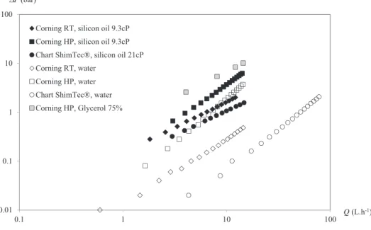
Fig.4showstheevolutionofpressuredropversusflowratefor
eachreactorandeachprocessfluidused.Foragivenfluid,Chart
ShimTec1reactorgenerateslesspressuredropthantheotherones.
Reactor
Q
=
6 L.
h
-1Q
= 10 L.
h
-1Corning
RT
0 0.5 1 1.5 2 20 15 10 5 0 E(t) (s-1) Time (s)Experimental inlet Experimental outlet
0 0.5 1 1.5 2 2.5 15 10 5 0 E(t) (s-1) Time (s)
Experimental inlet Experimental outlet
Corning
HP
0 0.5 1 1.5 2 20 15 10 5 0 E(t) (s-1) Time (s)Experimental inlet Experimental outlet
0 0.5 1 1.5 2 15 10 5 0 E(t) (s-1) Time (s)
Experimental inlet Experimental outlet
Chart
ShimTec
®
0 0.5 1 1.5 2 25 20 15 10 5 0 E(t) (s-1) Time (s)Experimental inlet Experimental outlet
0 0.5 1 1.5 2 2.5 15 10 5 0 E(t) (s-1) Time (s)
Experimental inlet Experimental outlet
Fig.3.DistributionfunctionsE(t)obtainedinthethreereactorsforQ=6Lh"1andQ=10Lh"1.
Table3
RangeofflowratesandReynoldsnumbersforRTDexperiments.
Flowrate(Lh"1) Re ffiffipS
CorningRT 6–12 850–1700
CorningHP 3–11 380–1420
ChartShimTec1
Thedivisionoftheflowinthreeparallelchannelsallowstoreduce
the averagevelocity per channelcompared to a single-channel
configurationwiththesamehydraulicdiameterwhilemaintaining
thesameglobalflowrate.Itconfirmsitscapabilitytodealwith
viscousfluidsorhighflowrates.Asexpected,CorningHPreactor
generatesmorepressuredropthantheotherreactors.Itspattern,
designedtoimprovemixingandtwo-phasetransferperformances
leads to larger energy dissipation into the fluid producing
significantpressuredrop.
ThepressuredropgeneratedinachannelisfunctionofFanning
frictionfactorf,density
r
,averagevelocityu0,lengthofthereactorL,its crosssectionareaSand itsperimeterPfollowing Eq.(7).
Therefore, it is possible to determine f from a pressure drop
measurement(Eq.(8)).
D
P¼1 2fr
u0 2L S (7) f¼2D
PSr
u02L (8)Fanningfrictionfactordependsonthegeometryofthechannel.
Forastraightsquarechannelithasdifferentempiricalexpressions
have been established depending on the flow regime [14]. In
laminarconditions(Re ffiffipS<2100):
fsquare¼ k1
Re ffiffipS (9)
Intransitionalflowforsmoothducts(2100<Re ffiffipS<10000):
fsquare¼k2Re ffiffip "0:25S (10)
(Blasiusequation)
Infullyturbulentflow(Re ffiffipS>10000):
fsquare¼k3 (11)
kiareconstantvaluesdependingontheshapeofthechannelcross
section.Fig.5representsFanningfactorversusReynoldsnumber.
Fromthisfigure,correlationsareproposedtopredictthepressure
dropinthethreereactorsstudied(Table4).
TheevolutionoftheFanningfrictionfactorforallthereactors
canbecomparedtotheoneinastraightsquarechannel.Forlow
Reynoldsnumber(Re ffiffipS<1000forCorningRTandChartShimTec1 Fig.4. Experimentalpressuredropversusflowrate.
0.001 0.01 0.1 1 10 10000 1000 100 10 1 f √ Corning RT Corning HP Chart ShimTec®
Straight square channel, laminar flow
Straight square channel (smooth), transitionnal flow
reactor and Re ffiffipS<50 for Corning HP) the trend observed
correspondstoEq.(9)associatedtoalaminarbehavior.
AnevolutiontothetransitionalregimeisobservedatRe ffiffipS¼
1000respectivelyforChartShimTec1andCorningRTandatRe ffiffi
S p
around 50 for Corning HP. Above these values, Fanning factor
valuesseemtofollowtheBlasiusequationtrend.Thedifference
betweenReynolds number values correspondingto theregime
changeforstraightpipeandforthereactorsstudiedmustbedueto
theparticulargeometriesofthereactors.Indeed,theChartreactor
iscomposed ofthreechannelswitha fewbends;CorningRTis
composedofarectangularchannelwithnumerous180!bendsthat
generate energy dissipation at lower Reynolds than straight
channels.The trend observed for Corning HP canbe explained
by the specific geometry of the channel which is designed to
generatemicromixingstructuresevenatlowReynoldsnumber.
ThelaminarregimeisonlyobservedforReynoldsnumberlower
than 50. Fanning factor seems to reach a constant value,
characteristic of a turbulent regime for Reynolds higher than
1000insteadof10000inastraightpipe.
3.2.RTDexperiments
Theglobalhydrodynamicbehaviorofchemicalreactorsisoften
characterizedbytheRTD.Itcorrespondstothetimenecessaryfor
different elements of fluid to pass through the reactor. It
determines if the reactorbehavior is closeto a perfect stirred
tankortoaplugflowreactor.RTDprovidesinformationaboutthe
Table4
TendenciesofFanningfrictionfactordependingontheflowregime.
CorningRT ChartShimTec1
CorningHP Re ffiffipS<1000:f¼ 16 Re ffiffipS Re ffiffipS<1000:f¼ 25 Re ffiffipS Re ffiffipS<50:f¼ 25 Re ffiffipS Re ffiffipS>1000:f0:08 Re0:25 ffiffi S p Re ffiffipS>1000:f¼ 0:33 Re0:25 ffiffi S p Re ffiffipS>1000:f¼0:2
Reactor
Q
=
6 L.
h
-1Q
= 10 L.
h
-1Corning
RT
0 0.5 1 1.5 2 0 5 10 15 20 E(t) (s-1) Time (s)Experimental inlet Experimental outlet Calculated outlet 0 0.5 1 1.5 2 2.5 0 5 10 15 E(t) (s-1) Time (s)
Experimental inlet Experimental outlet Calculated outlet
Corning
HP
0 0.5 1 1.5 2 0 5 10 15 20 E(t) (s-1) Time (s)Experimental inlet Experimental outlet Calculated outlet 0 0.5 1 1.5 2 0 5 10 15 E(t) (s-1) Time (s)
Experimental inlet Experimental outlet Calculated outlet
Chart
ShimTec
®
0 0.5 1 1.5 2 0 5 10 15 20 25 E(t) (s-1) Time (s)Experimental inlet Experimental outlet Calculated outlet 0 0.5 1 1.5 2 2.5 0 5 10 15 E(t) (s-1) Time (s)
Experimental inlet Experimental outlet Calculated outlet
mixingefficiencyanddefectssuchasstagnantregionsorshortcuts
thatcanlowertheperformancesofthereactor.RTD
characteriza-tionisthennecessarytomodelappropriatelyreactivesystems.
In a plug flow reactor, each element of fluid has the same
residence time. RTD experiments in a tubular reactor allowto
highlight a deviationfrom this idealbehavior. Thedeviation is
generally quantified by the Péclet number Pe. It comparesthe
convectivetransportandthediffusivetransportoverthelengthof
adeviceandisdefinedasfollows:
Pe¼u0L Dax
(12)
Peisdirectlyrelatedtotheaxialdispersioncoefficientthattakes
intoaccountallthephenomenainducingdispersioninareactor.
Axialdispersionisduetomoleculardiffusion,turbulenceand
non-uniformity of the velocityprofile. It is thus a key factor when
reactions with selectivity issues are considered [15,16]. This
dimensionlessnumberquantifiesthedifferencebetweenaperfect
stirredreactorandaplugflowreactor.Theplugflowbehavioris
assumedwhenPe>100[15].
Current methodologies for the characterization of axial
dispersionarebasedontheidentificationoftheaxialdispersion
coefficient fromRTDexperiments. It consistsin comparingthe
outletsignalwithananalyticalsolutionprovidedbyaconvection–
dispersionmodel[8,17,18]orasuccessionofperfectlymixedtanks
model[19].ThesemodelsimplyaperfectDiracinjectionthatis
experimentallydifficulttoperform.Totakeintoaccountthereal
injection, a deconvolution method is often used to treat the
entrancesignal[8,17].Butthismathematicaltreatmentcanleadto
alossofinformation,especiallyalossconcerningthetrailofthe
injection.
Another method is proposed in this work totreat the RTD
experimentswithoutdeconvolutionstep.Itconsistsinsolvingthe
one dimension convection–dispersion equation (Eq.(13))using
thecommercialsoftwareComsolMultiphysics.
@
c@
t þu0@
c@
x "Dax@
2c@
x2¼0 (13)WithInitialcondition:
t¼0:cðxÞ¼0 (14)
AndBoundaryconditions:
x¼0:cðtÞ¼cin;expðtÞ (15)
x¼L:
@
c@
x ¼0 (16)cistheaverageconcentrationoftraceroverthecrosssection.tis
timeandxthelongitudinalcoordinatealongthereactor(0*x*L).
At t=0, notraceris present in thereactor(Eq. (14)).The inlet
concentrationissetequaltotheexperimentalconcentrationcin,
exp(t) (Eq. (15)). At the outlet of the reactor the gradient of
concentrationissupposedtobezero(Eq.(16)).
Firstly, an initial value of Dax is chosen and the calculated
concentrationatx=L,cout,calc(t),iscomparedtotheexperimental
concentrationcout,exp(t).ThevalueofDaxisthenadjustedfollowing
the least squares method in order to minimize the s function
definedasfollows:
s¼
Z 1
0 ðcout;calcðtÞ"
cout;expðtÞÞ2$dt (17)
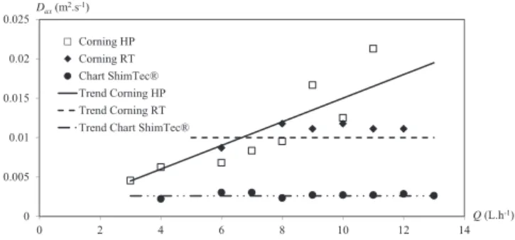
Fig.6givesexamplesofcalculatedE(t)curvewithidentifiedDaxby
minimization of the s function. This method is applied to
characterizethethree reactors.Daxisrepresentedasa function
of flow rate onFig. 7.The axial dispersioncoefficient remains
constantforbothCorningRTandChartShimTec1reactorswhile
the flow rate increases. For the Corning HP, this coefficient
increaseswiththeflowrate.Table5summarizesthesetendencies
andproposesacorrelationtocalculateDaxinthestudiedrangeof
flowratefortheCorningHP.
Fig. 8 shows the results of Péclet numbers as function of
Reynoldsnumberforeachindustrialreactor.Eachofthesethree
devicescanbeconsideredasaplugflowreactorforRe ffiffipS>400
sinceallthevaluesofPécletarerathercloseto100.InFigs.7and8,
theirregularity of thecurves is due tothe uncertainty on the
experimentalaxialdispersioncoefficients.Itisrelatedtothenoise
ontheabsorbancesignalswhichgeneratesanuncertaintyofabout
+0.05s"1onE(t)functions.ExtremevaluesofD
axareidentifiedby
adding and subtracting this uncertainty on RTD curves. The
resultinguncertaintyonDaxisaround+20%.
In Corning RTand Chart ShimTec1 reactors, Péclet number
increaseswithReynoldsnumber.Theplugflowbehaviorofthese
reactorsresultsofthevelocityofthefluid.Pécletnumberofthe
CorningHPreactorisquiteconstantaroundthevalue100inthe
studiedrangeofReynoldsnumber.Thiscanbeexplainedobserving
thegeometryofthechannel.TheHeartPatternhadbeendesigned
to generate mixing structures at low velocity. These mixing
structuresimplythehomogenizationofthetracer’sconcentration
across the section of the channel. In fact, each heart can be
consideredasindividualperfectmixedvolume.Thewholereactor
issocomposedofa successionof51equivalentstirredtanks.It
resultsinatheoreticalPécletnumberof100usingEq.(18)whereJ
correspondstothenumberofstirredtanksinseries[20].
Pe¼2ðJ"1Þ (18)
Therefore,theplugflowofthisreactorisduetothegeometryofits
channel, instead of being due to the velocity of the incoming
processfluidasitisforthetwootherreactors.
3.4.Discussion
Theaxialdispersioncoefficientsobtainedfromtheexperiments
arecomparedtomodelsavailableinliteratureforcircularpipes:(i)
themodelsuggestedbyTaylor[21]forlaminarflowand(ii)the
modelproposedbyLevenspiel[15]forturbulentflow.
For laminar flow in tubular pipes (Re<2100), Taylor model
givesarelationshipbetweentheaxialdispersioncoefficientDax,
themoleculardiffusioncoefficientDm,thehydraulicdiameterand
theaveragevelocity[21].
Dax¼Dmþu0 2D
h2
192Dm
(19)
Eq.(19)wasdemonstratedbyTaylor[21]inthecaseofsteady
flow.Thisequationgivesveryaccurateapproximationconsidering
0 0.005 0.01 0.015 0.02 0.025 0 2 4 6 8 10 12 14 Dax(m2.s-1) Q(L.h-1) Corning HP Corning RT Chart ShimTec® Trend Corning HP Trend Corning RT Trend Chart ShimTec®
that Daxonly depends on geometricaland physicalparameters
[22,23].
Inturbulentregime(Reh>2100)andforstraightcircularpipes
the relationship between the axial dispersion coefficient and
Reynoldsnumberiswrittenasfollows[15,24]:
Dax u0Dh¼ 3,107 Reh2:1 þ 1:35 Reh0:125 (20)
Fig.9 showstheevolutionofPéclet numberasafunctionof
Reynoldsnumber forastraight circularpipeusingbothmodels
(Eqs.(19)and(20)).ThelengthofthereactorissetatL=2mand
Dh=2mmwhich roughlycorresponds tothedimensions ofthe
Corning and Chart reactors studied.The experimental data are
added to the graph.The models predict that Péclet number
decreaseswhen Reynoldsnumber increasesin laminarflow.At
higher Reynolds number, Péclet number first increases with
Reynoldsnumber(2100<Reh<10000)andthentendstoreacha
constantvalue.
TheevolutionofPécletversusReynoldsobtainedforCorningRT
andChart ShimTec1 reactors in therange ofReynolds number
exploredissimilartotheevolutionobtainedinastraightpipein
thetransitionalregime.Itisconsistentwiththeinterpretationof
thepressuredropresults(Section3.1).TheconstantvalueofPe
experimentallyobtainedfortheCorningHPreactorcorrespondsto
the tendency observed in turbulent regime at high Reynolds
numbersin a straight pipe. This is still in agreement withthe
pressuredropcharacterizationdescribedinSection3.1.
4.Conclusion
Thisworkdescribesandcomparesthehydrodynamicsofthree
millistructured reactors. Pressuredrop is measuredin order to
estimatetheFanningfrictionfactor.RTDexperimentsarecarried
outinordertostudytheflowbehaviorofthesethreedevices.The
methodology usedin this work toidentifytheaxial dispersion
coefficientfromtheRTDcurvesisbasedonthecomputationofthe
convection–dispersionequation.Itallowstotakeintoaccountthe
realsignalshapeofthetracerinjectiontoavoidanytreatmentof
theexperimentaldatasuchasdeconvolutionthatcouldleadtoa
lossofinformation.
Thethreereactorshavedifferentgeometriesinaccordanceto
theapplicationtheyaredesignedfor.CorningHPreactorcanbe
consideredasamixer-exchanger.CorningRTislikelyusedto
pre-heatreactantbeforeareactionortoaddresidencetimeafterthe
reaction occurred. Chart ShimTec1 is used toperform reaction
withviscousfluids.Thesecharacteristicshaveanobviousimpact
onthehydrodynamicsofthereactors.Plugflowbehaviorofthese
threereactorsishighlightedbytheRTDanalysis.TheHeartPattern
particular geometrygeneratesmixing structures thatinduces a
plug flow behavior independently of the flow rate but is also
responsibleforthehighpressuredropobservedinthismodule.
Pressuredropmeasurementsshowthatthetransitiontoturbulent
regime is observed for Re ffiffipS¼50. In Corning RT and Chart
ShimTec1, the RTD experiments show that Péclet number
increaseswithReynoldsnumber.Thevelocityofthefluidenhances
plug flow behavior for these reactors. This last result is in
accordance with literature data for straight circular pipes in
turbulentregimeandcorroboratespressuredropresultswherethe
transitiontoturbulentregimeoccursaroundRe ffiffipS¼1000.
In ordertocomplete the hydrauliccharacterizationof these
reactors,furtherstudywillbeperformedintermsofmixingtime
asfunctionofflowrateandfluidproperties.
Acknowledgements
ThisworkhasbeensupportedbytheANR(AgenceNationalede
laRecherche),France:ProjectANRPROCIP,
ANR-2010-CD2I-013-01.Theexperimentalfacilitywassupportedby:theFNADT,Grand
Toulouse,PrefectureMidi-PyreneesandFEDERfundings.
AppendixA.
CorningHPreactor:estimationoftheequivalentcrosssection
andlength
EquivalentlengthandcrosssectionforCorningHPreactorare
identifiedbyusingtheRTDresults(8experiments).Indeed,these
parameters are fitted by comparing the experimental and
theoretical residence times (Eq. (A.1)) and the shapes of the
experimentalandcalculatedoutletcurvesE(t)wheretheaverage
velocityu0intheonedimensionconvection-dispersionequation
givenbyEq.(13)isobtainedfromthecrosssection(Eq.(A.2)).
tr;exp¼ LS Q (A.1) u0¼ Q S (A.2)
TheresultsintermsofcrosssectionandlengtharegiveninTable1.
References
[1]Z.Anxionnaz,M.Cabassud,C.Gourdon,P.Tochon,Heatexchanger/reactors (HEXreactors):conceptstechnologies:state-of-the-art,Chem.Eng.Process. ProcessIntensif.47(2008)2029–2050.
Table5
CorrelationofDax[m2s"1].ForCorningHP,DaxisexpressedasafunctionofQ[Lh"1].
CorningRT ChartShimTec1
CorningHP Dax[m2s"1] 0.0100+0.0020 0.0026+0.0005 (0.0015+0.0005)Q 0 50 100 150 200 250 0 500 1000 1500 2000 Pe √ Corning HP Corning RT Chart ShimTec®
Fig.8.EvolutionofPécletnumberasfunctionofReynoldsnumber.
0.01 0.1 1 10 100 1000 10000 10 100 1000 10000 100000 Pe h Corning HP Corning RT Chart ShimTec® Laminar flow (Taylor model) Turbulent flow
Fig.9.PécletnumberasfunctionofReynoldsnumber:models(L=2m,Dh=2mm,
[2]K.D.Nagy,B.Shen,T.F.Jamison,K.F.Jensen,Mixinganddispersionin small-scaleflowsystems,Org.ProcessRes.Dev.16(2012)976–981.
[3]S.Elgue,A.Conte,A.Marty,J.S.Condoret,Two-phaseenzymaticreactionusing processintensificationtechnologies,Chem.Today31(2013)6.
[4]S.Braune,P.Pöchlauer,R.Reintjens,S.Steinhofer,M.Winter,O.Lobet,etal., Selectivenitrationinamicroreactorforpharmaceuticalproductionunder cGMPconditions,Chem.Today27(2009)26–29.
[5]B.Buisson,S.Donegan,D.Wray,A.Parracho,J.Gamble,P.Caze,etal.,Slurry hydrogenationinacontinuousflowreactorforpharmaceuticalapplication, Chem.Today27(2009)12–14.
[6]M.S.Chivilikhinl,L.Kuandykovl,E.D.Lavric,R.Federation,F.Avon,Residence time distributionincorning1
advanced-flowTMreactors. Experimentand
modelling,Chem.Eng.Trans.25(2011)791–796.
[7]E.D.Lavric,P.Woehl,Advanced-flowTMglassreactorsforseamlessscaleup,
Chem.Today27(2009)45–48.
[8]A.Cantu-Perez, S.Bi,S.Barrass, M.Wood,A. Gavriilidis,Residencetime distributionstudiesinmicrostructuredplatereactors,Appl.Therm.Eng.31 (2011)634–639.
[9]Corning,Corning1
Advanced-FlowTMG1Reactor,http://www.corning.com/
WorkArea/showcontent.aspx?id=48113(2012).
[10]Chart, Compact Heat Exchange Reactors, http://www.chart-ec.com/pdf/ Compact-Heat-Exchange-Reactors.pdf,(2009).
[11]M.Bahrami,M.M.Yovanovich,J.R.Culham,Pressuredropoffully-developed laminarflowinmicrochannelsofarbitrarycross-section,J.FluidsEng.128 (2006)1036.
[12]G. Fate, D.G. Lynn, Molecular diffusion coefficients: experimental determinationanddemonstration,J.Chem.Educ.67(1990)536.
[13]V.Balakotaiah,H.C.Chang,Dispersionofchemicalsolutesinchromatographs andreactors,Philos.Trans.A351(1995)39–75.
[14]R.B.Bird,W.E.Stewart,E.N.Lightfoot,TransportPhenomena,2nded.,John Wiley&SonsInc.,NewYork,2007.
[15]O.Levenspiel,ChemicalReactionEngineering,3rded.,JohnWiley&SonsInc., NewYork,1999.
[16]D.W.Rippin,Simulationofsingle-andmultiproductbatchchemicalplantsfor optimaldesignandoperation,Comput.Chem.Eng.7(1983)137–156. [17]C.H. Hornung, M.R. Mackley, The measurement and characterisation of
residencetimedistributionsforlaminarliquidflowinplasticmicrocapillary arrays,Chem.Eng.Sci.64(2009)3889–3902.
[18]W.Roetzel,F.Balzereit,Determinationofaxialdispersioncoefficientsinplate heatexchangersusingresidencetimemeasurements,Rev.GénéraleTherm.36 (1997)635–644.
[19]Z.Anxionnaz-Minvielle,M.Cabassud,C.Gourdon,P.Tochon,Influenceofthe meanderingchannelgeometryonthethermo-hydraulicperformancesofan intensifiedheatexchanger/reactor,Chem.Eng.Process.ProcessIntensif.73 (2013)67–80.
[20]J.Villermaux,GéniedelaRéactionChimique,2nded.,Tec&Doc,Paris,1993. [21] G.Taylor,Dispersionofsolublematterinsolventflowingslowlythrougha
tube,Proc.A219(1953)186–203.
[22]W.N.Gill, R. Sankarasubramanian, Exact analysis ofunsteady convective diffusion,Proc.Roy.Soc.LondonA316(1970)341–350.
[23]W.N.Gill,Unsteadytubularreactors-timevariableflowandinletconditions, Chem.Eng.Sci.30(9)(1975)1123–1128.
[24]P.Trambouze,LesRéacteursChimiques–DelaConceptionàlaMiseenœuvre, Technip,Paris,1984.