Publisher’s version / Version de l'éditeur:
Questions? Contact the NRC Publications Archive team at
PublicationsArchive-ArchivesPublications@nrc-cnrc.gc.ca. If you wish to email the authors directly, please see the first page of the publication for their contact information.
https://publications-cnrc.canada.ca/fra/droits
L’accès à ce site Web et l’utilisation de son contenu sont assujettis aux conditions présentées dans le site LISEZ CES CONDITIONS ATTENTIVEMENT AVANT D’UTILISER CE SITE WEB.
3rd International Conference on Structural Health Monitoring of Intelligent Infrastructure (SHMIT-3) [Proceedings], pp. 1-12, 2007-11-14
READ THESE TERMS AND CONDITIONS CAREFULLY BEFORE USING THIS WEBSITE.
https://nrc-publications.canada.ca/eng/copyright
NRC Publications Archive Record / Notice des Archives des publications du CNRC :
https://nrc-publications.canada.ca/eng/view/object/?id=5dd3e697-adf9-4887-8cea-35349c6fa9a1 https://publications-cnrc.canada.ca/fra/voir/objet/?id=5dd3e697-adf9-4887-8cea-35349c6fa9a1
NRC Publications Archive
Archives des publications du CNRC
This publication could be one of several versions: author’s original, accepted manuscript or the publisher’s version. / La version de cette publication peut être l’une des suivantes : la version prépublication de l’auteur, la version acceptée du manuscrit ou la version de l’éditeur.
Access and use of this website and the material on it are subject to the Terms and Conditions set forth at Field condition monitoring of water mains in the Canadian prairies
http://irc.nrc-cnrc.gc.ca
F i e l d c o n d i t i o n m o n i t o r i n g o f w a t e r m a i n s i n
t h e C a n a d i a n p r a i r i e s
N R C C - 5 0 2 5 4
C h a u d r y , T . S . ; G h e o r g h i u , C . ; H u , Y .
A version of this document is published in / Une version de ce document se trouve dans: 3rd International Conference on Structural Health Monitoring of Intelligetn Infrastructure (SHMII-3), Vancouver, B.C., Nov. 14-16, 2007, pp. 1-12
The material in this document is covered by the provisions of the Copyright Act, by Canadian laws, policies, regulations and international agreements. Such provisions serve to identify the information source and, in specific instances, to prohibit reproduction of materials without written permission. For more information visit http://laws.justice.gc.ca/en/showtdm/cs/C-42
Les renseignements dans ce document sont protégés par la Loi sur le droit d'auteur, par les lois, les politiques et les règlements du Canada et des accords internationaux. Ces dispositions permettent d'identifier la source de l'information et, dans certains cas, d'interdire la copie de documents sans permission écrite. Pour obtenir de plus amples renseignements : http://lois.justice.gc.ca/fr/showtdm/cs/C-42
FIELD CONDITION MONITORING OF WATER MAINS IN THE CANADIAN PRAIRIES
Tariq Saleem Chaudry University of Manitoba, Canada
Catalin Gheorghiu University of Manitoba, Canada
Yafei Hu NRC Centre for Sustainable Infrastructure Research, Canada
Abstract
Water distribution systems are gradually deteriorating due to ageing, operational stresses and external environmental conditions. This deterioration has resulted in increased operation and maintenance costs, or in some cases a reduction in the water quality or reliability of service supplied to customers. There is a need for a clear understanding of the behaviour of water mains under various conditions so municipalities can manage water distribution systems efficiently.
To understand soil behaviour and pipe–soil interaction under operating conditions, a field monitoring project has been set up. A section of asbestos cement (AC) pipe has been instrumented to monitor the performance of water mains in an older area of the City of Regina, which has experienced frequent pipe breakage in recent years. The instrumentation includes sensors for monitoring the longitudinal and circumferential strains along the pipe section, soil displacement, soil moisture content, soil pressure, and pipe temperature and soil temperatures at different depths. Data from this field monitoring system will serve as a basis for research on the failure mechanisms and performance of AC water mains in the expansive clay soil conditions of the Prairies.The paper presents analysis of the measurements taken from strain and temperature sensors during the initial months of installation (September 2006 to January 2007). Preliminary results indicate that the pipe experienced no significant flexural strains. The temperature drop decreases with the increasing depth of the trench.
This project is unique in the sense that it is the first Intelligent Sensing for Innovative Structures (ISIS) application of monitoring water mains using fibre-optic sensors (FOS), and is a joint project with the National Research Council Centre for Sustainable Infrastructure Research (NRC-CSIR) in Regina, Canada.
INTRODUCTION
In the City of Regina, two thirds or approximately 531 km of the water mains are made of asbestos cement (AC). These pipes have experienced more and more failures in recent years and account for most of the water main breaks in the city. To ensure that Regina can manage its water
distribution network in a cost-effective, reliable and sustainable manner, it is essential that a clear understanding exist of AC pipe failure conditions and mechanisms.
A recent study [1] investigated the breakage pattern of the AC water mains for the 1980 to 2004 period in the City of Regina to assess the conditions and identify factors that influence the breakage of these water mains. It was observed that the pipe age, diameter, climate, soil
conditions, construction and repair methods all contribute to pipe failures with climate and soil conditions being the two critical factors. Peaks in water main failures have been observed during the extreme dry and cold seasons. The observed monthly break pattern during the 25-year period was similar to that of Winnipeg where similar soil conditions exist [2].
Another work [3] analyzed the pipe breakage data of cast iron (CI) and AC water mains in the City of Winnipeg for the 1948 to 1953 period and observed that the monthly number of circumferential failures had a cyclic pattern with peaks occurring in September and January. The circumferential breakage pattern was compared with the monthly mean temperatures, precipitation and approximate depth of snow cover in the City of Winnipeg, and a close correlation with
seasonal climate changes was observed. It was suggested that the high swelling–shrinkage potential of soil in this area has a significant impact on these failures. Three test installations consisting of CI and AC mains were instrumented to monitor the pipe movement. Upward displacement was observed during the investigation and the maximum differential movement along the buried pipe was 20 mm in all three test installations. Such movements induce flexural stresses in the pipe, potentially leading to circumferential failures or joint failures, especially in small diameter mains [1].
A broader study [4] analyzed data from four water authorities with inventory of AC pipes, one with clay soil and the other three in sand and gravel conditions. It was observed that the distribution of water main failures was fairly random, during the year, in the areas with sand and gravel, whereas most of the failures in areas of predominantly clay soil occurred during the dry summer months. Two peaks in the annual failure rate were observed over the period from 1952 to 1982, and they corresponded to two hot summers with long dry periods, indicating higher
shrinkage. The high occurrence (over 97%) of circumferential failures and the large proportion of failures of small diameter mains (over 98% being 75, 100 or 150 mm diameter) suggests that circumferential failures caused by high flexural stresses induced by soil movement around the pipe prove detrimental for small diameter AC mains [1].
It can be inferred from the preceding discussion that for pipes buried in expansive soils, the occurrence of water main failures is closely correlated with the variation in soil moisture content during extreme climate conditions. Montmorillonite clay with high swelling/shrinkage
characteristics is dominant in the City of Regina. Reduction of soil moisture in dry summer seasons results in the shrinkage of cohesive soil. This shrinkage is also observed in winter. This phenomenon is believed to be caused by the progressive freezing of the water in the soil, which draws pore water from lower depths (i.e., around the pipe) [5]. As a result of less percolation of
surface water during winter, the reduced moisture content at lower depths causes soil shrinkage. The changes in soil volume with the fluctuation in soil moisture result in soil movement. The movement of soil around the water mains results in flexural stresses through different mechanisms, such as non-uniform bedding support or differential settlement.
To better understand the soil’s behaviour and the corresponding responses of water mains under expansive soil conditions, a field instrumentation and monitoring system has been set up to continuously monitor the performance of an AC pipe section. The preliminary strains and
temperature measurements obtained from the sensors installed on the AC pipe section are discussed here.
FIELD INSTALLATION
A section of AC pipe was installed in a residential area of the City of Regina. The location selection was based on a number of factors including the number of breaks that occurred during the past five years, access to a power source and space for putting up the instrumentation enclosure (Hu et al., 2007).
Trench Excavation and Backfill
Field installation was carried out between September 11, 2006 and September 15, 2006. A trench, 2.5 m wide, 5.9 m long and 2.6 m deep was excavated (Figure 1), and the existing AC pipe section, which was 2.2 m below the ground surface, was removed. An instrumented section of pipe was installed in the trench and sensors was carried out at different levels. The external instrumentation box is shown in Figure 2.
Sand provided by the City of Regina was used as backfill material for the haunch and bedding areas throughout the trench. Mixed concrete, a blend of recycled crushed concrete and subbase gravel with a ratio of 2:1 by weight, was used from the pipe haunch up to 150 mm above the top of the pipe. The trench was backfilled and compacted up to the pavement level using several 150 mm thick native soil layers according to the specifications recommended in [6].
Figure 1: Installation of Instrumented AC Pipe Section Figure 2: Data Acquisition System
Replacement of Existing Pipe Section
The existing pipe was 150 mm in diameter (Class 150) AC pipe originally installed in 1961. The new instrumented AC pipe had the same dimensions as the original one (Table 1). The new AC pipe was connected to adjacent sections of AC pipe using robars [7].
Table 1: Asbestos Cement Pipe Dimensions
Parameter Pipe Dimensions
Nominal diameter (mm) 150 Outer diameter (mm) 183 Inside diameter (mm) 146 Length (m) 4.0
Soil Conditions
The soil at the site consists of highly plastic lacustrine clay from the surface to a depth of 8.5 m with glacial till beneath it. The soil conditions at the site were assessed in four sample boreholes. One borehole was 800 mm south of the centre line of the pipe and the other three were about 2, 5 and 12.1 m north of the pipe, respectively.
MONITORING SYSTEM
The monitoring system provides a range of data, which will serve as a basis in the ongoing study on failure mechanisms of AC pipes (Hu, 2004). The layout of the sensors on the AC pipe is shown in Figure 3. The sensing system includes:
• 24 electrical strain gauges (ESG) on the exterior pipe surface for measuring longitudinal and circumferential strains;
• two long gauges (LG) for measurement of circumferential strains;
• eight fibre Bragg grating (FBG) fibre-optic sensors (FOS) for measurement of longitudinal and circumferential strains;
• 25 thermocouples on the pipe surface and in the surrounding backfill material for temperature measurements;
• four pressure cells at the pipe level to measure changes to soil pressure;
• 20 time domain reflectometry (TDR) probes for measurement of moisture content in the backfill;
• 16 Fredlund thermal conductivity sensors for measuring soil suction and temperature; and
• two vibrating wire piezometers for measuring water pressure inside the pipe and soil pore water pressure.
Strain Measurement
Electrical strain gauges (ESG) were installed to measure the deformation response of the AC pipe. A general-purpose WK-06-250TM-350 ESG was selected from Micro-Measurements for this purpose. Three sets of strain gauges were installed equally spaced along the pipe length. Each set consisted of four pairs of gauges, one on the top of the pipe, one on the bottom of the pipe and the other two on the spring line. Each pair of strain gauges provides both longitudinal and
circumferential strain readings.
Three dummy strain gauges mounted on small rectangular coupons prepared from AC pipe of identical specifications together with three thermocouples, one for each dummy strain gauge, were placed in the backfill as close as possible to the ESG-instrumented cross sections. The deformation due to temperature alone is measured by the dummy strain gauges and is used to correct the deformation measured by the strain gauges on the pipe surface.
Fibre-Optic Sensors
Ten FOS were installed to measure strain in the pipe section. Two 1 m long gauge sensors were placed around the pipe at Section C-C (Figure 3) to measure hoop strains in the AC pipe. Two sets, consisting of four FBGs were installed at Sections B-B and C-C next to the ESG. Fibre Bragg gratings at Section B-B were aligned to measure the longitudinal strains, whereas at Section C-C, they were aligned to measure circumferential strains.
Temperature Measurement
Thermocouples were placed on the surface of the pipe adjacent to the strain gauges, in the backfill, as well as on the surface of the pipe coupons. Twenty-five type T thermocouples were installed during the field work: 12 thermocouples on the exterior pipe surface, 3 thermocouples adjacent to dummy strain gauges and 10 thermocouples in the backfill.
Data Acquisition System
A CR1000-55 data-logging system from Campbell Scientific Inc. was installed to collect the data from the electrical strain gauges. The data-logging equipment is housed on-site in a metal
instrumentation box installed 1.2 m north of the trench (Figure 2). Readings are recorded hourly from these sensors. The FOS data acquisition system (DAQ) consists of IDERS SHM 5100-A for the FBG sensor, and FOX-TEK FTI-3300 FT for the long-gauge strain sensors. The fibre-optic sensor readings are taken periodically for a period of approximately one hour.
RESULTS AND DISCUSSION
The measurements obtained from the ESG, FOS and thermocouples are discussed in the following. Preliminary FBG results are presented herein. The first set of FOS readings was recorded on January 23, 2007. Analysis of ESG readings from September 2006 to January 2007 is presented followed by readings taken on January 23, 2007 for a 24-hour period. The strain readings have been corrected for temperature and include the deformation due to stresses and temperature. A comparison between the relative change in ESG and FBG measurements is presented for a one-hour period on January 23, 2007.
Electrical Strain Readings between September, 2006 and January 31, 2007
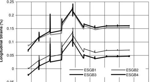
The longitudinal strains recorded at the midspan, Section B-B of the pipe are shown in Figure 4. The strain curves are obtained by plotting hourly strain data from two days in a month, the 15th and the last day of the month. A straight line joins the two days together assuming a linear variation.The longitudinal strains at the top (ESGB1) and bottom (ESGB3) are almost identical, indicating that the pipe is experiencing mainly axial stresses without significant bending stresses. The strain gradually increased to reach a peak around mid-November, and then decreased to a plateau at about 0.15% (ESGB1 and ESGB3) and 0.05% (ESGB2 and ESGB4) by mid-December 2006. The longitudinal strains observed at the other cross-sections along the pipe show a similar pattern.
Figure 5 shows the measured circumferential strains at the midspan. Similar to the
longitudinal strains, the pipe experienced a significant increase in circumferential strain until mid-November and then attained a steady state in the range of 0.05% to 0.1%. The circumferential strains at the other cross-sections show a similar pattern.
Figure 4: Longitudinal Strains versus Time at Section B-B
-0.05 0 0.05 0.1 0.15 0.2 0.25
31-Aug 20-Sep 10-Oct 30-Oct 19-Nov 09-Dec 29-Dec 18-Jan 07-Feb 27-Feb
Date Lon git udi nal Str a ins ( % ) ESGB1 ESGB2 ESGB3 ESGB4
-0.05 0 0.05 0.1 0.15 0.2 0.25
31-Aug 20-Sep 10-Oct 30-Oct 19-Nov 09-Dec 29-Dec 18-Jan 07-Feb 27-Feb
Date C irc umfe re ntia l Str a ins (% ) ESGB1 ESGB2 ESGB3 ESGB4
Figure 5: Circumferential Strains versus Time at Section B-B
Electrical Strain Readings for a 24-Hour Period (January 23, 2007)
Figures 6 and 7 show the variation of the longitudinal and circumferential strain at Section B-B during a 24-hour period on January 23, 2007. A strain value is recorded every hour for all gauges. From midnight to about 11h00, longitudinal strain readings are constant. A gradual increase is noticed to reach a peak at 15h00. At that particular time, water pressure in the network reached a maximum of 421 kPa, 21 kPa higher than nominal water pressure. From this moment on, a gradual decrease is noted until midnight. Similar behaviour is observed for the circumferential strains (Figure 7), and the other instrumented cross-sections.
Electrical and FOS Strain Readings for a One-Hour Period
Figure 8 shows relative longitudinal strains recorded on January 23, 2007 for an hour by the ESG and FOS installed at Section B-B. Since ESG strain measurement is taken every hour, two values are joined to form the straight lines for ESGB1 and ESGB2. For the FBG sensors, a higher sampling rate was used. The two instruments measure similar strains, and in this case the
difference of 0.005% is insignificant. The relative change of strain values measured by ESG and FOS will be further observed during a longer term monitoring process.
Temperature Readings
Figure 9 shows the average temperatures recorded from some of the thermocouples located at different depths throughout the trench between September 2006 and January 2007. The results
show high variation in temperatures closer to the ground surface. At pipe level and below, the temperature dropped at a fairly stable rate but did not go past the freezing point.
0 0.02 0.04 0.06 0.08 0.1 0.12 0.14 0.16 0.18 0.2 0:00 2:00 4:00 6:00 8:00 10:00 12:00 14:00 16:00 18:00 20:00 22:00 Time Longitudin a l Strains (%) ESGB1 ESGB2 ESGB3 ESGB4
Figure 6: Hourly Variation of Longitudinal Strains at Section B-B on January 23, 2007
0 0.02 0.04 0.06 0.08 0.1 0.12 0.14 0.16 0.18 0.2 0: 0 0 2: 0 0 4: 0 0 6: 0 0 8: 0 0 10 :00 12 :00 14 :00 16 :00 18 :00 20 :00 22 :00 Time Cir cumf erent ial St rains (%) ESGB1 ESGB2 ESGB3 ESGB4
-0.04 -0.035 -0.03 -0.025 -0.02 -0.015 -0.01 -0.005 0 0.005 0 10 20 30 40 50 6
Time Elapsed (minutes)
R e lative S trai n (%) 0 FBGB1 FBGB2 ESGB1 ESGB2
Figure 8: Comparison of FBG and ESG Strains at Section B-B on January 23, 2007 (15h00-16h00)
-15 -10 -5 0 5 10 15 20
31-Aug 20-Sep 10-Oct 30-Oct 19-Nov 9-Dec 29-Dec 18-Jan 7-Feb 27-Fe
Date Tempera ture (°C ) 2499 mm 1329 mm 781 mm 362 mm
Depth from Ground Level
Figure 9: Temperature versus Time at Different Levels in Trench
CONCLUSION
The instrumented AC pipe section was installed successfully in the City of Regina water mains distribution network as a part of ongoing research on the failure mechanisms and behaviour of AC water mains. This pipe monitoring installation is the second one of a project within the City, and is the first Canadian FOS application for water main monitoring. For the current installation,
up-to-date preliminary strain and temperature measurements were presented. Soil temperature readings show seasonal and depth variations that were to be expected. Strain data varied significantly especially immediately after the installation. This initial strain variation has been mainly caused by backfill soil compaction. Daily variation was noticed for both longitudinal and circumferential strain in the installed pipe section. The change is mainly caused by the daily variation of water pressure in the distribution network. The collected data from the sensors will be utilized in developing soil-pipe interaction models of AC pipes and pipes made from other materials (e.g., polyvinyl chloride pipes) in expansive clay soil conditions. The field monitoring of water mains together with planned laboratory and theoretical studies will significantly contribute toward a better understanding of water main behaviour in harsh environmental conditions.
ACKNOWLEDGMENTS
This project is primarily funded by the National Research Concul Centre for Sustainable
Infrastructure Research (NRC-CSIR) in Regina, SK, wit significant in-kind support from the City of Regina. The financing of the Univeristy of Manitoba and FOS portion of this project was provided by the Network of Centres of Excellence ISIS Canada and is gratefully acknowledged. The authors thank Evangeline Murison and Trevor Nadeau of the SHM Support Center at the University of Manitoba and Kaveh Lotfian of NRC-CSIR for their technical assistance.
REFERENCES
1. Hu, Y. and Hubble, D.W., 2005. “Failure conditions of asbestos cement water mains in Regina”,
Canadian Society for Civil Engineering (CSCE) 33rdAnnual Conference, Toronto, Ontario, June
2-4, 2005, FR-135:1-10.
2. Hu, Y. and Vu, H.Q., 2006. “Field performance of water mains buried in expansive soil”,
Canadian Society for Civil Engineering (CSCE) 34th Annual Conference, Calgary, Alberta,
Canada, May 23-26, 2006, ST106:1-13.
3. Baracos, A., Hurst, W.D. and Legget, R.F., 1955. “Effects of physical environment on cast iron pipe”, American Water Works Association Journal, 42:1195-1206.
4. Mordak, J. and Wheeler, J., 1988. “Deterioration of asbestos cement water mains”, Final Report
to the Department of Environment, Water Research Center, Wiltshire, UK.
5. Shah, K.R. and Razaqpur, A.G., 1993. “A two-dimensional frost-heave model for buried pipelines”, International Journal for Numerical Methods in Engineering, 36:2545-2566.
6. City of Regina, 2004. “Standard construction specifications”, Third Electronic Edition, City of Regina Engineering and Works Department.
7. Hu, Y. 2004. Failure Mechanisms of Asbestos Cement Water Mains – Research Proposal to the City of Regina. Centre for Sustainable Infrastructure Research, NRC, Regina.
8. Hu, Y., Vu, H. and Lotfian, K., 2007. “Field installation of an instrumented section of water main pipe on Cross Place, September 11 to 15, 2006”, Progress Report #SIR1001.2, Centre for Sustainable Infrastructure Research, National Research Council, Regina, SK.