Publisher’s version / Version de l'éditeur:
Vous avez des questions? Nous pouvons vous aider. Pour communiquer directement avec un auteur, consultez la première page de la revue dans laquelle son article a été publié afin de trouver ses coordonnées. Si vous n’arrivez pas à les repérer, communiquez avec nous à PublicationsArchive-ArchivesPublications@nrc-cnrc.gc.ca.
Questions? Contact the NRC Publications Archive team at
PublicationsArchive-ArchivesPublications@nrc-cnrc.gc.ca. If you wish to email the authors directly, please see the first page of the publication for their contact information.
https://publications-cnrc.canada.ca/fra/droits
L’accès à ce site Web et l’utilisation de son contenu sont assujettis aux conditions présentées dans le site LISEZ CES CONDITIONS ATTENTIVEMENT AVANT D’UTILISER CE SITE WEB.
International Conference on Building Envelope Systems and Technology
[Proceedings], pp. 1-12, 2007-03-01
READ THESE TERMS AND CONDITIONS CAREFULLY BEFORE USING THIS WEBSITE. https://nrc-publications.canada.ca/eng/copyright
NRC Publications Archive Record / Notice des Archives des publications du CNRC :
https://nrc-publications.canada.ca/eng/view/object/?id=e2ac1118-acef-4d9e-8285-169ffdc5d825 https://publications-cnrc.canada.ca/fra/voir/objet/?id=e2ac1118-acef-4d9e-8285-169ffdc5d825
Archives des publications du CNRC
This publication could be one of several versions: author’s original, accepted manuscript or the publisher’s version. / La version de cette publication peut être l’une des suivantes : la version prépublication de l’auteur, la version acceptée du manuscrit ou la version de l’éditeur.
Access and use of this website and the material on it are subject to the Terms and Conditions set forth at
Advancements and changes in the North American commercial roofing
industry
A d v a n c e m e n t s a n d c h a n g e s i n t h e N o r t h
A m e r i c a n c o m m e r c i a l r o o f i n g i n d u s t r y
N R C C - 4 9 2 7 6
B a s k a r a n , B . A . ; P a r o l i , R . M . ; K a l i n g e r , P .
A version of this document is published in / Une version de ce document se trouve dans: International Conference on Building Envelope Systems and Technology, Bath, U.K., March 2007, pp. 1-12
The material in this document is covered by the provisions of the Copyright Act, by Canadian laws, policies, regulations and international agreements. Such provisions serve to identify the information source and, in specific instances, to prohibit reproduction of materials without written permission. For more information visit http://laws.justice.gc.ca/en/showtdm/cs/C-42
Les renseignements dans ce document sont protégés par la Loi sur le droit d'auteur, par les lois, les politiques et les règlements du Canada et des accords internationaux. Ces dispositions permettent d'identifier la source de l'information et, dans certains cas, d'interdire la copie de documents sans permission écrite. Pour obtenir de plus amples renseignements : http://lois.justice.gc.ca/fr/showtdm/cs/C-42
ADVANCEMENTS AND CHANGES IN THE NORTH AMERICAN COMMERCIAL ROOFING INDUSTRY
Dr. Bas. A. Baskaran and Dr. Ralph M. Paroli, National Research Council Canada, 1200 Montreal Road, Ottawa, ON, Canada K1A 0R6
Mr. Peter Kalinger, Technical Director, Canadian Roofing Contractors’ Association, 2430 Don Reid Drive, Ottawa, ON, Canada K1H 1E1
ABSTRACT
Building envelopes are designed to separate the controlled indoor environment from the outdoor
environment. The building envelope consists of roofs, walls, windows and basement. A roof is an integral assembly of a building envelope and the 2005 North American roofing market was more than $25 billion Canadian.
During the past decade (1996 to 2006), the roofing community underwent several
advancements and changes. To spark discussion and debate within the roofing community, this paper reviews some of them:
• Advancement in material technology and application process • Proportion of reroofing compare to new construction
• Increase in residential construction due to low interest rate • Increase in the number of hurricane events
• Skyrocketing of insurance premium for contractors • Government polices towards sustainable construction
The North American roofing community has also made significant advancement in the dynamic
wind evaluation of commercial roofs through a North American roofing consortium, Special Interest Group for the Dynamic Evaluation of Roofing Systems (SIGDERS). SIGDERS was established to develop a North American wind uplift test standard for roofing systems under dynamic conditions in 1994. This paper also presents results from the SIGDERS ongoing research effort, including an overview of a new publication, “A Guide for the Wind Design of Mechanically Attached Flexible Membrane Roofs”.
INTRODUCTION
The envelope of a building is critical as it has both functional and aesthetic values. It must shelter its occupants from the external factors. It must also keep them warm during winter, cool in the summer as well as safe from wind and tornados. A critical component of any building envelope is the roof. The roof should comprise high performance and durable materials to protect a building from nature’s harshest elements. Roofs are expected to fulfil various functions for considerable periods, under extremely harsh conditions. They are expected to provide water tightness and near-continuous protection from moisture and vapour, ultraviolet exposure, cyclic thermal loads, cold, noise, wind and fire.
A roof assembly contains a roof system over a roof deck. The roof system is defined as having the elements, which cover, protect and insulate the roof of a structure against the external environment. Roof systems vary from the traditional types (e.g., built-up roofing (BUR)) to the non-traditional (e.g., polymer-based single-ply or modified bitumen). They also vary in the method by which the covering has been put down. The conventional method is to have the covering (e.g., membrane) above the insulation and exposed to the environment. Alternatively, in a protected system, the covering is directly below the insulation.
CANADIAN ROOFING MARKET
In Canada, the average sales volume in 2000 was $3.7 Billion with a projected average of approximately $3.9 Billion for 2001 [CRCA, 2001]. According to the last survey conducted by the Canadian Roofing Contractors’ Association (CRCA) in 2000 new construction and re-roofing has equal market share. This is true both in low− and steep−slope activities. Figure 1 shows the three main low−slope roofs in Canada and their average market shares for new construction and reproofing. Organic asphalt shingles dominated the steep-roof market in 2000 with an average sale of 43% of the new construction and re-roofing whereas for fibreglass asphalt singles the average sales was 17% for new construction and re-roofing. The average sales for other systems (steep-slope) for new and re-roofing was: metal roof 16%, bitumen 13%, single-ply 2%, BUR 2% and others 3%.
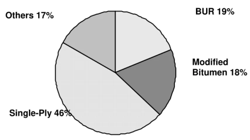
For United States, the average market shares (low-slope) for new construction and re-roofing are given in Figure 2. More details can be found from the 2004 National Roofing Contractors Association (NRCA) Survey [Good, 2005]. The US market shows an increase in the single-ply market of about 5% compared to 1995 while the modified bituminous market has been steady. The BUR market seems to have decreased during the 10-year period.
Single-Ply 13%
Others 5%
BUR 27%
Modified Bitumen 55%
Figure 1. Average market share for low-slope roofs in Canada in 2000 (Canadian Roofing Contractors’ Association, 2000–2001 Annual Market Survey.)
Single-Ply 46%
Others 17% BUR 19%
Modified Bitumen 18%
CURRENT ISSUES OF THE NORTH AMERICAN ROOFING COMMUNITY Membrane Choices
The choice of low-slope roofing membranes and configurations available to designers and building owners has increased dramatically over the past decades. Traditional systems, such as asphalt and gravel asphalt b.u.r., are competing against a variety of elastomeric and plastomeric Single Ply (SP) membranes, including Ethylene Propylene Diene Monomer (EPDM), Poly Vinyl Chloride (PVC), Thermoplastic Polyolefin (TPO) and Modified Bituminous Membrane (MBM).
There are several factors that account for the rise in popularity of these “non-traditional” systems including flexibility, manufactured quality and uniformity, reduced load requirements and lowered overall installed costs1.
The relative reduction in the weight of the membrane system allows for the use of lighter and more flexible structural decks. It should be noted that these efficiencies are only realized when the roofing system’s wind uplift resistance is achieved without the use of a heavy gravel or ballast overburden. In SP and MBM systems on steel decks, this is achieved by mechanically attaching the membrane roof cover to the deck at discrete locations or by the use of adhesives resulting in greater reliance on the ability of the membrane and attachment devices to resist wind blow-off.
Manufacturers of these membrane systems claim that they offer lower installation costs. EPDM, by example, is available in rolls covering 929 m² (10,000 sq. ft.). Some manufacturers offer SP systems with sheet widths up to 3.6 m (12 ft.) wide, resulting in fewer seams to weld and fewer sheets to install. Factory granule coated MBM sheets eliminate the need for field applied surfacing. Savings are not merely the result of larger sized or finished sheets. Mechanization, manifested in the use of robotic and numerically controlled welders, fastening machines, and adhesive dispensers has significantly decreased the cost of installing them. Other technical advances, such as self-adhering membranes, in-seam tapes, and custom fabricated sheet sizes have further reduced installed costs.
Labour Market
Although these innovations have reduced the amount of labour required, the technical
complexity of the application of these products and systems has raised the necessary skill level of the installer at a time when finding and retaining skilled workers is more and more difficult. Strong growth in the North American construction industry has placed increasing demands on a limited supply of skilled construction labour. In 2005, the construction GDP in Canada was approximately 6 % of total GDP, with similar activity in the U.S2.Much of this expansion was in the residential sector, due to low interest rates and changes in mortgage requirements3. Although residential construction is expected to weaken over the next few years, strong growth is predicted for the non-residential sector that, coupled with the impending wave of retirements of baby boomers, will lead to severe shortages of skilled labour over the next several years underscoring the need for supplier-based training in proprietary technologies4.
Competition for scarce resources due to the strong economic growth occurring domestically and in other parts of the world, combined with political instability and a series of natural disasters
1 Traditional b.u.r. low-sloped roofing membrane systems consist of several reinforcing plies set into
adhesive layers of hot asphalt. Although this multi-step process provides a high degree of redundancy, the on-site construction, especially under less than ideal weather conditions, makes it difficult to achieve uniform quality of finished product. In SP and MBM systems, factory applied quality assurance provides a greater degree of consistency of the finished membrane.
2 Construction Sector Council, A Snapshot of the Construction Industry.U.S. Department of Commerce,
Bureau of Economic Activity, December, 2006.
3 Construction Sector Council. Construction Looking Forward, 2006.
have impacted the price and availability of all construction materials in recent years. Gypsum, cement, fibreboard and many metal products have been in short supply, leading to allocations and double digit price increases. The greatest volatility has been in the petroleum and natural gas sector. The price of liquid asphalt jumped over 40 % nationwide in the U.S. in 20065. Cost escalation of natural gas, a raw material for SP membranes, foam insulations and many other roofing materials, caused by increased demand, depleted domestic supplies and refinery interruptions have led to significant price increases6. The search for processes, materials and designs that reduce input costs and increase production accounts for much of the recent growth in SP and MBM systems.
Increasingly, contractors are implementing cost reduction strategies that include pre-fabrication, mechanization, task elimination through the use of less labour intensive systems and designs, and the use of lighter and less energy intensive components. The many features of SP and MBM systems, including reduced labour requirements, light weight, and environmental benefits combine to make them a viable alternative to more traditional systems. However, the success of these systems depends on understanding their mechanical behaviour, particularly as they relate to their wind performance.
The initial development of non-traditional low-slope roofing materials and systems resulted primarily from the technical considerations of building more durable systems at lower cost. Today, larger socio-economic concerns are combining to shape our industry. Not the least of these are the principles of achieving sustainable growth, energy efficiency and protection of the environment.
Government Polices Towards Sustainable Construction
Our buildings and infrastructure are being scrutinized to see whether the materials we use and how they are assembled may mitigate the negative environmental effects of urban growth and human activity. As roofs typically represent a large portion of an urban community’s surface area, building owners and designers, manufacturers and contractors are looking at ways of building roofs that will maximize energy performance and reduce energy demand and consumption.
Many of the roofing materials we use have been purposely developed and engineered with enhanced environmental properties including their improved recyclability, low environmental impact with respect to disposal, and lower energy costs during production. It is widely accepted that we can positively impact our environment by building eco-friendly roofs. These benefits are acknowledged in the current version of the LEED® (Leadership in Energy and Environmental Design) rating system by the award of points for the design and construction of reflective or garden roofs. Roofing membranes, such as flexible, light coloured SPs, are being installed not only for their waterproofing properties, but also for their potential beneficial impact on energy consumption and the urban heat island effect.
Weather Events and Its Impact
As lightweight, flexible and energy efficient roofing systems are being more frequently specified, the demands on them, particularly in terms of wind performance are escalating. Whether the result of global warming or a natural cyclical occurrence, most areas of North America are experiencing an increase in severe hurricanes and other windstorm events. According to the insurance industry’s Institute for Catastrophic Loss Reduction, damage due to these events has increased dramatically in recent years, incurring losses of life and property around the world7.
5 Construction & Demolition Recycling magazine, June, 2006 6
Hurricane Katrina interrupted oil production, importation, and refining in the Gulf area, thus having a
major effect on fuel prices. Before the storm, one-tenth of all the crude oil consumed in the United States and almost half of the gasoline produced in the country came from refineries in the states along the Gulf's shores. Power outages in the wake of Katrina also caused distribution problems for oil and natural gas.
7 The 2005 Atlantic hurricane season was the most active in recorded history, shattering previous records,
Canada, once considered immune to such major storms, has recently experienced the devastation caused by significant wind events. Just in the past few years, severe windstorms have battered all regions of Canada, from the Atlantic through to the Pacific coasts8.
Environment Canada has issued warnings advising that severe windstorm activity is on the upswing and we should expect many more similar storms in the decades to come.
The roofing industry has reacted to the rising frequency and severity of the increased frequency of major wind events in several ways. In the aftermath of catastrophic property losses suffered during the 2005 hurricane season, North America’s leading roofing systems approval and certification organization, FM Global, significantly increased the requirements for attachment and subsequent wind resistance for fully adhered built-up, modified bitumen, and single ply membranes over insulation mechanically fastened to steel decks. Building codes have been revised to make their wind resistance requirements more stringent9.
ADVANCES IN WIND UPLIFT RESEARCH
The North American roofing community has made significant advancement in the dynamic wind evaluation of commercial roofs through a North American roofing consortium, Special Interest
Group for the Dynamic Evaluation of Roofing Systems (SIGDERS). SIGDERS was established
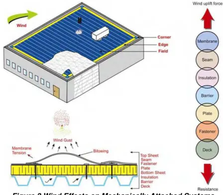
to develop a North American wind uplift test standard for roofing systems under dynamic conditions in 1994 and progress was reported by Baskaran et al (1997). This section presents the advancements during the last decade (1996 – 2006), including an overview of a new publication, “A Guide for the Wind Design of Mechanically Attached Flexible Membrane Roofs”. In such roofs, wind dynamics lift the membrane and cause fluttering, introducing stresses at the attachment locations (Figure 3). Each component offers a certain resistance to the wind uplift force. This can be illustrated through a force-resistance link diagram. All resistance links should remain connected for the system to be durable and to keep the roof properly in place. Failure occurs when the wind uplift force is greater than the resistance of any one or more of these links.
Figure 3 Wind Effects on Mechanically Attached Systems
8 Early in 2006, winds gusting to more than 80 km/h tore through New Brunswick downing power lines
leaving estimated 200,000 business and homes without electricity. During November 2006 to January 2007, a series major storms swept through British Columbia’s lower mainland blowing roofs off of buildings and bringing down hydro lines.
9 The return period used to determine the reference velocity pressure due to wind for the design of
Development of a New Dynamic Test Method
Testing is required to determine the wind resistance of a roof assembly. Roof system component manufacturers provide design resistance values for their systems based on uplift testing. It is critical to use a test method that provides a meaningful measure of the uplift performance of the system. SIGDERS’ goal was to develop a method that would:
mimic real wind effects
achieve failure modes observed under real conditions be easier to apply in the laboratory than existing tests allow for variation in roof design
produce results quickly conform to local standards.
SIGDERS’ test method was developed based on wind tunnel studies of full-scale roof
assemblies. Under simulated wind flow conditions, roofing systems were tested in the 9 m by 9 m NRC wind tunnel. The roofing systems were 3 m by 3 m in size and used full-scale roofing components. The influences of all four roofing components (deck, under layment, insulation, and membrane) were considered. Two series of wind tunnel investigations, one in November 1994 and the other in October 1995, were carried out using two distinct roofing membranes. The first series dealt with a reinforced PVC membrane and the other with a non-reinforced EPDM membrane. The roof region was divided as “perimeter”, “field”, and pressure time histories were measured. For the PVC system, there were 30 different test configurations, whereas in the case of the EPDM system, 48 configurations were tested.
A computer program was developed to count the occurrences of a pressure amplitude level from the pressure time histories. A rain flow counting method was applied to compute the number of cycles. To develop a laboratory procedure for certifying full-scale roofing assemblies, the above data were reorganised into different pressure zones with their respective number of cycles. Eight pressure zones were selected under two groups. Group #1 represents wind-induced suction over a roof assembly. It consists of four sequences, where the pressure level alternates between zero and a fixed pressure. Group 2 represents the effects of exterior wind fluctuations combined with a constant interior pressure on a building. In Group 2, a constant minimum static pressure is applied to the roof system, and the gusts are applied above this constant static pressure. The roof membrane is lifted by static pressure; thus, Group 2 mimics membrane tension effects that are aimed to simulate fatigue at the fastener locations.
Based on the this technology advancement, a new North American test standard was adopted and published by the Canadian Standards Association (CSA A123.21-04 – Standard Test
Method for the Dynamic Wind Uplift Resistance of Mechanically Attached Membrane Roofing Systems). The standard has also comprehensively documents, procedures for lab data
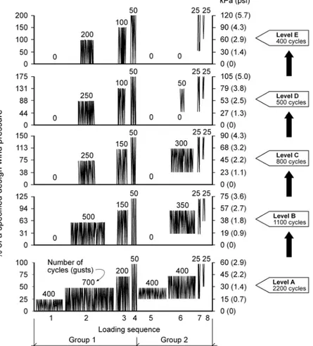
recording and standardized form for data reporting. One of the major contributions of the standard is the load cycle development. Technical details on the development of the load cycle are documented in Baskaran, Chen, and Vilaipornsawai (1999). As shown in Figure 4, the load cycle has five rating levels (A to E).
Each level consists of eight load sequences with different pressure ranges. The eight load sequences can be divided into two groups.
Group 1 represents wind-induced suction over a roof assembly. It consists of four sequences, where the pressure level alternates between zero and a fixed pressure. Group 2 represents the effects of exterior wind fluctuations combined with a constant interior pressure on a building. Internal pressure variations are explicitly codified in the recent NBCC (2005) and ASCE (2005) documents. The SIGDERS test protocol accounts for such variations.
The test pressure ratios (y-axis) can be calculated from the design pressure, in accordance with the NBCC – Part 4 or ASCE - 7. The pressures for each load sequence are calculated as percentages of the test pressure. An example is shown with a test pressure of 60 psf (2.87 kPa) on the right hand side of the axis.
To evaluate the ultimate strength of the roofing system, testing should be started at Level A and, if it passes, it should be advanced to the next level and so on. To obtain an uplift resistance, all specified numbers of gusts in a given level must be completed. This new development can assist roof designers and manufacturers in North America to evaluate and specify flexible membrane roofs under dynamic environment.
Figure 4 New North American Dynamic Load Cycle for Wind Resistance Evaluation Publication of a New Wind Design Guide
The resistance of the roof assembly to wind uplift is a function of the components used (membrane, seams, fasteners, deck, etc.) and their arrangement. By applying the developed load cycle, SIGDERS has tested a wide range of systems with different roof covering materials, including PVC, TPO, Mod Bit and EPDM. The failure mechanism and failure load compare favourably with the UEAtc test procedure that calls for a large number of low-intensity cycles (Gerhardt, 1989). In addition, the failure modes produced by the SIGDERS load cycle is also similar to the failure modes observed during field investigations.
As more than 200 systems were evaluated. Data from these extensive investigations were documented in a 107-page Guide, which will help advance the design and construction of durable roofing systems. The Guide is illustrated with over 60 colour figures and photographs. This comprehensive publication (Baskaran and Smith, 2005) presents the following information:
characteristics of mechanically attached roof systems an outline of the wind design process
a review of a new dynamic wind uplift testing protocol and a comparison to other protocols now in use
detailed example wind load calculations for Canada and the United States, based on the new National Building Code of Canada 2005 and the American Society of Civil Engineers procedure ASCE 7-02 respectively
an overview of design procedures for wind uplift resistance in the two countries
material characteristics and component selection for decks, air and vapour retarders (barriers), insulation and membranes.
From the Guide, three key contributions are presented below. Deck Attachment vs. Membrane Attachment
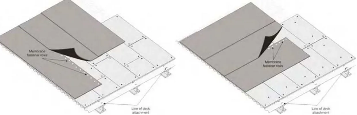
The deck and the deck attachment are essential features for resisting the complex and dynamic wind load distribution of mechanically attached flexible membrane roof systems. Steel decking is a common material used to support flexible membrane mechanically attached roofs. The specification of the steel deck needs to consider the grade, the attachment method and membrane row orientation. The deck attachment to the supporting structure must be sufficient to resist the design uplift loads (adjusted for the safety factor). The deck attachment should be equal to or greater than the attachment used in the assembly the designer references to determine the roof assembly’s uplift resistance. It is desirable for the membrane fasteners to engage the top flange of the deck, because top flange engagement reduces the moment arm of the fastener and minimizes localized deck deformation.
The orientation of the fastener rows with respect to the deck flanges affects the influence area of the deck attachment to the support structure. The influence area is defined as the area that contributes uplift load to the connection of the deck to the supporting structural beam/joists. During the membrane attachment, the membrane fastener row can align either parallel (Figure 5a) or perpendicular (Figure 5b) to deck flanges. If the membrane fastener rows are
perpendicular to the flanges, the influence area is decreased. This results in a lower load being transferred to the deck attachment. Also, perpendicular row layout avoids the potential of overstressing the deck side lap fasteners. Therefore, specifying fastener rows perpendicular to the deck flanges is recommended. Parallel row attachment can cause deck attachment failure (Figure 5a). At either end or at the edge of the roof that is parallel to the fastener rows,
additional rows of fasteners should be specified between the primary rows to accommodate the additional uplift load that occurs at corners and the perimeter. The supplementary rows can be fasteners and plates, battens or bars placed over the membrane and attached.
Figure 5 Membrane Fastener Attachment Row a) Parallel and b) Perpendicular to the Deck Attachment
Effect of Air/Vapour Barrier (Retarder) on Wind Uplift Resistance
In general, air barriers (AB) are intended to control airflow into the roof system, whereas vapour barriers (VB) limit vapour diffusion into the roof system. Vapour barriers also limit airflow. However, some air barriers are not resistant to vapour flow. This section addresses the functions of those air and vapour barriers (retarders) that affect the wind uplift performance of mechanically attached flexible membrane roofs by means of their ability to control airflow. In Canada during the 1960s, VB were introduced to control vapour diffusion in walls
(Handegord, 1960). Since then, VB have become a research focus at the Institute for Research in Construction at the National Research Council of Canada – NRC-IRC (formerly known as
Division of Building Research – DBR). As new materials and system designs evolve, NRC-IRC continues to respond to the needs of the construction industry in addressing issues relating the overall performance behaviour and requirements of such materials. On going efforts include research on the fundamentals of vapour diffusion in building materials and assemblies (Kumaran et al, 1994), the development of new standards (Kumaran, 1998) and updating the building codes and best practices (Quirouette, 1985). In the USA during the past decade, researchers Tabiasson (1996) studied the need for a VB in roof assemblies. Based on those works, valuable design guidelines were developed and made available for designers in ASHRAE fundamental handbook. The majority of the efforts are limited in finding ways to limit the vapour diffusion movements in building envelope. Some VB materials also have the
property of resisting airflow. At this time, no studies exist which address such effect of VB on the wind uplift performance of roof assemblies. A need for such understanding is more critical now than ever as the market share for new single ply roof assemblies is significantly increasing in comparison to the conventional built up roofs.
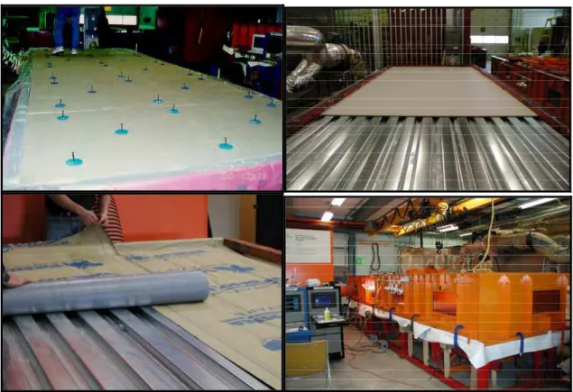
Systems with and without VB/AB were installed at the Dynamic Roofing Facility (DRF) (Figure 6) and subjected to CSA dynamic load cycle. Figure 7 shows the measured response data for four systems. System 1 (NOVB) sustained a maximum pressure of 4.3 kPa (90 psf) and passed all eight sequences of Level A of the CSA test protocol. This means that the system
configuration passed the gusts applied over a constant static pressure component in Group 2 (refer to Figure 4), as well as those in Group 1. System 2 (Felt paper), System 3 (Poly) and System 4 (Self-Adhered Membrane (SAM)) sustained a maximum pressure of 6.5 kPa (135 psf) and passed all necessary sequences up to Level C. It is clear that the wind uplift performance is improved on systems with vapour barrier. An improvement of about 50% has been measured in the wind uplift rating for systems with vapour barrier. This is found true for all barrier types. It is worth to caution that the 50% improvement is not due to the ability of the vapour barrier to reduce the moisture diffusion rather its property to resist air movements.
9 0 13 5 13 5 13 5 0 2 0 4 0 6 0 8 0 10 0 12 0 14 0 Wind Uplift (psf)
No V B/AB # Fe lt P olye t hyle ne S AM
Specimen
Figure 7 Comparison of the System Wind Uplift Rating with Different VB/AB Innovations in the Membrane Seam Design
There are two families of mechanically attached membrane systems: polymer-based and asphalt-based. Some mechanical and physical properties (for example, tensile strength and dimensional stability) of the membrane itself can influence wind uplift performance of the roof system, while other physical properties (for example, membrane colour) are of little significance. The membrane attachment method can significantly influence wind uplift performance of the roof system. Attachment method variables include the number and type of fasteners, thickness and type of battens, gauge and type of plates, and width and type of seams. Dynamic testing is the preferred method for evaluating the wind uplift performance of membranes.
Attachment Methods and Considerations: The different attachment methods result in different force distributions. The more non-symmetrical the forces, the greater the design challenges. The Guide identifies the force distributions created by the attachment method for the wind uplift design. By understanding wind-induced forces, one can design the roof system components to accommodate the forces.
Asymmetrical Seams: The asymmetrical seam attachment arrangement is the most common one for mechanically attaching thermoplastic membranes. Asymmetrical seams are subject to higher eccentric force distributions and membrane stress than other types of seams. Under high winds, an asymmetrical seam (Figure 8a) can experience forces that can cause:
seam peeling, fastener back out, or pullout from the deck
tearing in the membrane in the vicinity of the attachment or the seam permanent deformation of the fastener plates
crushing of the substrate below the plate due to overturning forces on the fastener plate crushing of insulation due to rocking forces on the fastener shank.
Symmetrical Seams: Compared to asymmetrical seams, symmetrical double-sided seams offer two major advantages. First, the wind load is transferred by two seamed areas at each seam location instead of one as in the case of the asymmetrical arrangement. Second, since twice the seamed area is available to share the load, the load borne by each seamed area is reduced (Figure 8b).
Systems with symmetrical seams can be expected to withstand higher wind loads than systems with asymmetrical seams (Baskaran, 2002). In symmetrical seams, batten strips can also spread the wind uplift along the length of the seam rather than localizing it at the fasteners or in the membrane around the vicinity of the fastener plates. The majority of the wind uplift forces are transferred to the deck through a structural load path with minimal eccentricity. During the wind uplift testing, induced fastener forces were measured using a force balance specially developed at the NRC. The force balance has the capacity to measure simultaneously both vertical and horizontal forces. As discussed, one should expect reduction in the horizontal force for systems with symmetrical seams. This theoretical concept has also been verified by
SIGDERS. For the horizontal component, comparisons between the symmetrical and asymmetrical systems are shown in Figure 8c. They are presented as ratios at different
pressures. These ratios are obtained by dividing measured force at each loading sequence with the maximum measured force from the asymmetrical system. The data indicate that the
horizontal forces were reduced by about 50% due to the symmetrical seams. 0.40 0.20 0.70 0.27 0.87 0.33 1.00 0.40 1.00 0.50 0.00 0.30 0.60 0.90 1.20 Load Ratio 15 30 45 60 75 Wind Pressure, psf Asymmetrical Seam Symmetrical Seam
Figure 8 Asymmetrical and Symmetrical Seams and its Influence on Wind Performance Systems with asymmetrical seams failed due to membrane tear around the fastener plate. Closer examination of the failure showed that the membrane had been stretched around the plate, and then torn completely away from around the plate, while the fasteners remained engaged with the deck. There was also an instance of delamination failure, as the membrane peeled slightly at one fastener location. Examination of the system’s seams after the test revealed that the membrane had experienced some stretching, and bore teeth marks from the metal fastener plates. Kramer (1994 and 1995) quoted the most common observed failure for membrane roofs as, “Slippage of roof membrane from below attachment plate leading to loss of
compression between roof membrane, insulation substrate, and fastening elements and ultimately to membrane failure by way of tear spread around the fastener shaft”. This
observation coincides with SIGDERS failure mode and indicates that the SIGDERS load cycle is inducing representative wind dynamics on roof systems.
CONCLUDING REMARKS
To spark discussion and debate within the roofing community, this paper reviewed some of the advancements and changes during the past decade (1996 to 2006). Advancement in material technology and application process is changing the North American market share from the conventional BUR system to single ply systems. The North American roofing community has
also made significant advancement in the dynamic wind evaluation of commercial roofs through a consortium, Special Interest Group for the Dynamic Evaluation of Roofing Systems
(SIGDERS). The SIGDERS consortium research has resulted in testing protocol and design guide and will continues to advance the understanding and behaviour of flexible roofs. Government polices towards sustainable construction are starting to influence the market changes for the next decade.
REFERENCES
ASCE. 2005. “Minimum design loads for buildings and other structures”, ASCE Standard 7 05, American Society of Civil Engineers, Reston, Va.
Baskaran, A., Paroli R. M. and Booth R. J. (1997), “Wind performance evaluation procedures for roofing systems current status and future trends,” Fifth International Conference on Building Envelope Systems and Technology, BATH, U.K., pp. 37-52.
Baskaran, A.; Chen, Y.; and Vilaipornsawai, U. (1999) "A New Dynamic Wind Load Cycle to Evaluate Flexible Membrane Roofs" ASTM, Journal of Testing and Evaluation 27(4).
Baskaran, A., (2002) “Dynamic Wind Uplift Performance of Thermoplastic Roofing System with New Seam Technology”, ASCE, Journal of Architectural Engineering, Vol. 8, No. 4, December 1, 2002.
Baskaran, A. and T.L. Smith. 2005. A Guide for the Wind Design of Mechanically Attached Flexible Membrane Roofs. National Research Council of Canada, Ottawa, Ontario, Canada, K1A 0R6.
Canadian Roofing Contractors’ Association, 2000–2001 Annual Market Survey. Gerhardt, H.J. 1989. “Roofing Membrane-Observed Damage, Failure Modes, Failure
Hypotheses and Laboratory Testing”, Proceedings of the Roofing Wind Uplift Testing Workshop, Oak Ridge, Tennessee, pp.19-34.
Good, C. National Roofing Contractors Association (NRCA) Professional Roofing Magazine, “Surveying the Roofing Market,” April 2005.
Handegord, G.O. 1960. “Vapour Barriers in Home Construction”, Canadian Building Digest, 9. Kramer, C. 1994. “Damage and Damage Analysis of Roofing System for Large Industrial Flat Roof Building”, Proceedings of International Conference on Building Envelope Systems and Technology, Nanyang Technological University, Singapore, pp. 573-578.
Kramer, C. 1995. “Typical Failure Modes of Building Envelopes”, 9th International Conference on Wind Engineering, New Delhi, India, pp. 1231-1242.
Kumaran, M.K., G.P. Mitalas and M.T. Bomberg, 1994. "Fundamentals of transport and storage of moisture in building materials," ASTM Manual on Moisture Control in Buildings, MNL 18. Kumaran, M.K. 1998. “Inter Laboratory comparison of the ASTM standard test methods for water vapour transmission of materials" Journal of Testing and Evaluation, 26, (2), pp. 83-88. NBCC. 2005. National Building Code of Canada 2005, Canadian Commission on Building and Fire Codes, National Research Council of Canada, Ottawa. (Part 5).
Quirouette, R.L. 1985. “The Difference Between a Vapour Barrier and an Air Barrier”, Building
Practice Note, Division of Building Research, National Research Council Canada, 54.
Tobiasson.W, 1996. “Vents and vapour Retarding for Roofs”, Proceedings of the Symposium on Air Infiltration, Ventilation and Moisture Transfer, Building Thermal Envelop, pp 187-197.
ACKNOWLEDGEMENTS
The presented research is being carried out for a consortium - Special Interest Group for Dynamic Evaluation of Roofing Systems (SIGDERS). These partners included:
Manufacturers: Atlas Roofing Corporation, Canadian General Tower Ltd., Carlisle Syn. Tech.,
GAF Materials Corporation, Genflex Roofing Systems, Firestone Building Products Co., IKO Industries Canada, ITW Buildex, Johns Manville Corporation, Sarnafil Ltd., Stevens Roofing systems, Soprema Canada, Tremco and Trufast
Building Owners: Canada Post Corporation, Public Works and Government Services Canada. Industry Associations: Canadian Roofing Contractors' Association, Canadian Sheet Steel