HAL Id: hal-01858594
https://hal.archives-ouvertes.fr/hal-01858594
Submitted on 12 Mar 2020
HAL is a multi-disciplinary open access
archive for the deposit and dissemination of
sci-entific research documents, whether they are
pub-lished or not. The documents may come from
teaching and research institutions in France or
abroad, or from public or private research centers.
L’archive ouverte pluridisciplinaire HAL, est
destinée au dépôt et à la diffusion de documents
scientifiques de niveau recherche, publiés ou non,
émanant des établissements d’enseignement et de
recherche français ou étrangers, des laboratoires
publics ou privés.
Gilles Lenoir, Véronique Aubin
To cite this version:
Gilles Lenoir, Véronique Aubin. Mechanical Characterization and Modeling of a Powder-In-Tube MgB
2 Strand. IEEE Transactions on Applied Superconductivity, Institute of Electrical and Electronics
Engineers, 2017, 27 (4), pp.1 - 5. �10.1109/TASC.2016.2629481�. �hal-01858594�
Mechanical characterization and modeling of a
Powder-In-Tube MgB
2
strand
G. Lenoir and V. Aubin
Abstract—The strain dependence of superconducting material is known to be responsible for the degradation of the electrical performance of cables. As such, their electrical optimization requires an understanding of their mechanical behavior. The present paper introduces a method for elasto-plastic modeling of commercial MgB2 multi-filamentary strands manufactured by
the ex-situ powder-in-tube method. The model is based on a simplified representation of the structure, built using components’ volume fractions and nano-indentation test data. Monotonic and cyclic tension-compression tests were performed on the strands before and after chemical dissolution of the Monel outer layer to provide a multi-scale experimental database. These tests were used to identify the parameters of the kinematic and isotropic hardening laws of the elasto-plastic model. The model intends to be subsequently used to simulate the electrical behavior of cables and define guidelines for the manufacturing process, cabling process and end-product operating condition.
Index Terms—Superconducting strand, mechanical behavior, modeling, MgB2, Multi-scale mechanical tests.
I. INTRODUCTION
UPERCONDUCTING cables are assemblies of twisted strands. A strand is a composite wire with superconducting filaments twisted in a metallic matrix resulting in a complex, multi-scale structure. It is well known that the strain state of the strands, depending on loading conditions, affects the electrical performance of cables [1], [2]. This dependency has been well studied since initial work by [3]. The manufacturing process, cabling process and operating conditions lead to tension-compression and bending loadings on the strands in cables [4].
The COCASCOPE project aims to model the behavior of superconducting cables at different scales for the optimization of their electrical performance. In the framework of this project, a commercial MgB2 strand used in superconducting
cables based on the "react-and-wind" process was studied. Several studies have investigated the mechanical properties of MgB2 strands with different structures [5]-[9]. However,
electrical modeling requires an accurate description of the mechanical behavior of the strand. Studies have previously been performed to model the mechanical behavior of Nb3Sn
Automatically generated dates of receipt and acceptance will be placed here; authors do not produce these dates. This work was supported in part by the French “Agence Nationale de la Recherche” (ANR) under the COCASCOPE project.
The authors are with the laboratory of Mechanics, Structures and Materials (MSSMat) – UMR CNRS 8579, CentraleSupélec, 92295 Châtenay-Malabry, France (e-mail: gilles.lenoir@centralesupelec.fr; veronique.aubin@centralesupelec.fr).
based strands using various approaches [10]-[14]. Cyclic behavior with Bauschinger effect is rarely taking into account in these models, except by [14]. In this paper, we propose a method to model the mechanical behavior of superconducting strands thorough macroscopic, mesoscopic and microscopic approaches. This method is applied to a commercial MgB2
strand. The constitutive equations are built for future use in multi-scale finite element simulations to predict the mechanical behavior [15] or the electrical behavior [16], [17].
II. MODELING OF THE COMPOSITE STRUCTURE A. Samples
The MgB2 strands were manufactured by Columbus
Superconductors with an ex-situ Powder-In-Tube (PIT) method. A cross-sectional image of the strand is shown in Fig. 1(a). Two strands with a diameter of 1.33mm and 1.55mm were tested. Each strand includes thirty-six MgB2
filaments, surrounded by a Nickel inter-filamentary matrix and an outer layer of Monel. Fig. 1(b) shows two reaction layers with porosities at the interface of an MgB2 filament and the
Nickel matrix. These layers were created by diffusion of Magnesium from MgB2 into the Nickel matrix.
B. Numerical representation of the strand
The first step of the modeling is to represent the complex composite structure of the strand by a simplified one which can be implemented in finite element simulation. To choose a well-adapted representation of the strand structure, the study of the strand components is required.
Given the small scale of the microstructure, nano-indentation tests are well-suited for characterizing the local mechanical properties of each component. During nano-indentation, a precisely-dimensioned indenter tip is pressed into the surface of the material to a pre-defined depth measured from the position of the tip and a previous definition
S
Fig.1. SEM observations of (a) the MgB2 strand and (b) enlarged view at
of the surface of the sample. The load and the penetration depth are recorded. Oliver and Pharr [18] showed that the nano-hardness H and the elastic modulus E can be determined from the indentation test load-depth curve and the geometry of the indenter. Tests were performed with a commercial nano-indenter with a Berkovich tip (three-sided diamond pyramid) and using the Continuous Stiffness Measurement (CSM) mode [19]. The indents were 200 nm in depth with a width of around 1.4 µm. This indent size made it possible to characterize each constituent phase individually. The tests were performed in several transverse cross-sections. Table I summarizes the results with the number of indents and standard deviation for each measurement. Two diffusion layers have been characterized, one adjacent to the MgB2 and one adjacent to
the Nickel. Nano-indentation in the MgB2 was not possible
due to its porous structure. Results in the literature (EMgB2
=76-172 GPa [9], [20]) show a strong dependence on the manufacturing process, material structure and measurement methods. The Young’s moduli of Monel and Nickel measured by nano-indentation tests are in agreement with published values (EMonel=160-185 GPa [8], [21] and ENi=186-207 GPa
[9], [22]) regarding the different manufacturing processes. Nano-hardness is related to the initial size of the elastic domain and can be used to constrain the elastic limits when optimizing model parameters as described in Section III. The diffusion layers are purely elastic in the loading range but their behavior is closer to the one of Nickel than that of MgB2.
The volume fractions of components were determined by area measurements on images of the transverse cross-section of the strand. Observations were performed both using SEM with backscattered electrons and an optical microscope. Cross-sectional samples were prepared by manual polishing followed by vibro-polishing. Table II summarizes the volume fractions obtained grouped by set. The standard deviation in Table II corresponds to the difference between measurements made on SEM and optical observations of the transverse cross-section. Porosities are observed at the interface between MgB2
filaments and diffusion layers, as in Fig.1(b). Voids were also observed in the MgB2 phase, due to its porous structure. For
this reason, it was not possible to distinguish the volume fraction of MgB2 and porosities. The volume fraction of the
{Nickel, diffusion layers} set was calculated from the areas of the inter-filamentary zone minus the area of the {porosities, MgB2} set.
To predict the electrical performance, the stress and strain predictions in the filaments are required. A model has thus been developed to predict the mechanical behavior of the composite strand. From the structure of the strand and the
microscopic results, we defined three sets to represent the composite structure: an outer-layer set, a matrix set and a filament set. The outer-layer set is composed of the Monel and has an elasto-plastic behavior. The matrix set is composed of the diffusion layers and the Nickel. It is also modeled with an elasto-plastic constitutive law. As it was not possible to measure precisely the porosity volume fraction of the porous MgB2 filaments the filament set is composed of both MgB2
and porosities with an elastic behavior in the domain studied. C. Elasto-plastic modeling
Each set has its own behavior as described above. Various approaches can be used to calculate the elasto-plastic response of a material. Plastic modulus or power laws are usually used in literature for elasto-plastic modeling of superconducting strands [10]-[13], [16]. However, this kind of model is not well-adapted to describe cyclic behavior and more particularly the Bauschinger effect. To be able to predict the cyclic response of the strand, it is necessary to introduce kinematic hardening variables [14], [23].
For a single material, the model assumes that a domain exists where the behavior remains linear elastic and can be described by Hooke’s law. Once the limit of this elastic domain is reached, the behavior of the material becomes plastic. The evolution of this domain characterizes the macroscopic mechanical response of the material. A variable R characterizes the evolution of its diameter (isotropic hardening) and X the displacement of the elastic domain (kinematic hardening). The changes of these hardening variables are defined by [23]:
Q R
p b R (1) p C ε X X p (2)where b and γ represent the hardening rates, Q and C the saturation values and the plastic state is described by the plastic strain tensor εp and accumulated plastic strain p.
The classical von Mises criterion is selected to describe the boundary of the elastic domain. It is represented by:
0 R ) ( : ) ( 2 3 ) R , , ( f σ X SX SX 0 (3)
where S is the deviatoric part of the stress tensor σ and σ0 is
the initial size of the elastic domain.
D. Parallel materials consideration for composite structure The mechanical behavior is based on a composite description of the strand in which the microstructure is shared out among three sets, as defined in Section II.B. The filament set has an elastic response in the domain studied. The elasto-plastic models for the outer layer and the matrix are calculated separately.
The composite model assumes homogeneous strain in the NANO-INDENTATIONS RESULTS
COMPONENTS Num. of indents E 1 (GPa) SD 2 (GPa) H 3 (GPa) SD 2 (GPa) Ni in matrix 513 204 7 1.6 0.1 Ni in core 144 204 5 1.7 0.2 Monel 40 170 5 2.1 0.1
Diff. layer adj. Ni 24 191 15 11 1.4 Diff. layer adj. MgB2 39 215 6 12 0.8
1 Elastic modulus, 2 Standard Deviation and 3 Nano-hardness
VOLUME FRACTION OF MONEL,{NICKEL, DIFFUSION LAYERS} AND
{POROSITIES,MgB2} Monel {Porosities, MgB 2} {Nickel, diff. layers} Average Area (mm²) 0.728 0.225 0.419 Volume fraction fv 0.531 0.164 0.305 Standard Deviation 1.1x10⁻³ 0.2x10⁻³ 1.3x10⁻³
strand and a stress distribution in the components that depends on component volume fractions defined as:
o m f s
(4) o o v m m v f f v s f f f (5)where the subscript s stands for strand, f for filament, m for matrix and o for outer layer.
III. IDENTIFICATION PROCESS A. Step of identification process
The elasto-plastic mechanical behavior described by constitutive equation is based on kinematic and isotropic hardening laws which depend on material parameters. These parameters need to be identified by defining an inverse identification problem. The identification process uses observable variables (here stress and strain) determined from experimental data. The set of parameters retained is the one for which the comparison between the experimental response and the simulated response is considered satisfactory. The methodology is synthetized in Fig. 2.
The first step consists in calculating the response of the model to an experimental loading. It is done by numerically solving the mechanical differential systems using a fourth order Runge-Kutta method. Then the simulation is compared to the real behavior by calculating the difference between the experimental response and the calculated one. A cost function is used, defined as the normalized least square error:
2 exp 2 simu 2 exp cost y y y f (6)where y is the stress response (resp. strain) when the test is controlled in strain (resp. stress) and the subscripts exp and simu mean experimental and simulated, respectively.
The identification of the material parameters consists thus in an optimization problem solved by iteratively generating a set of parameters and calculating the cost function in order to minimize it. A specific strategy of identification, detailed in Section III.B., and various optimization methods were used successively to obtain a set of parameters physically representative of the mechanical behavior of the strand and
avoiding local minima. B. Identification strategy
The material parameters of the model are • Outer layer: fvo / Eo / σyo / bo / Qo / Co / γo,
• Filaments: fvf / Ef,
• Matrix: fvm / Em / σym / bm / Qm / Cm / γm,
where σy designates the yield stress of each component.
Ideally, tests would be carried out on each individual material to correctly identify their parameters. Due to the manufacturing process and their composition, the Nickel, diffusion layers and MgB2 are not available independently.
Bars of Monel having the same composition as the outer-layer specified by Colombus Superconductors have been tested. To access to the parameters of the matrix, tests on strands after dissolving the Monel outer layer, called inter-filamentary area strands, were carried out and described in Section IV.B.
The volume fractions fvo, fvf, fvm are measured from image
analyses. Elastic moduli Eo and Em are defined from
nano-indentation tests: Eo=EMonel and Em=ENi. Elastic limits σyo and
σym are evaluated by tests on Monel bars and inter-filamentary
area strands. They will be accurately identified during the optimization process by using the nano-hardness results detailed in Table II and literature values from [26] as limits.
As MgB2 is porous, it is not possible to measure its elastic
modulus by nano-indentation tests. It has to be evaluated using the composite nature of the strand. Indeed, the elastic modulus of the filaments set Ef should verify the two following mixture
laws, expressed at the strand scale (7) or at the inter-filamentary scale (8): m m o o f f S fv E fv E fv E E (7) m m f m f m f f IFA fv fv E fv E fv fv fv E (8)
The elastic moduli measured on the complete strands ES and
the inter-filamentary area strands EIFA allow to calculate the
filament elastic modulus Ef from (7) and (8). One can observe
in Table III that results do not agree. This difference may be explained by the difficulty to handle inter-filamentary strands before and during mechanical tests, which may cause more damage, and then lowers the apparent elastic modulus of the inter-filamentary strand. Nevertheless, to remain compatible with both experiments on complete and inter-filamentary area strands during the identification process, a compromise for Ef
at 120 GPa has been chosen.
The volume fractions and elastic moduli remain constant during the optimization process. Several tests exploring various ranges and types of loadings were used to ensure a wide domain of prediction and the uniqueness of the set of parameters. To differentiate isotropic and kinematic hardening components for cyclic modeling, both monotonic tensile tests Fig. 2. Methodology of the identification process.
TABLEIII
ELASTIC MODULI MEASURED FROM TENSILE TESTS AND AS CALCULATED
SAMPLES E measured
(GPa) SD
*
(GPa) Ef calculated (GPa) SD
*
(GPa) Complete strand 180 8.5 167 50 Inter. Filament. strand 160 8.8 78 25
with plastic unloads and cyclic tests were used.
To ensure that each parameter of a set has a physical meaning, we identified σyo/bo/Qo/Co/γo from tests on Monel
Bars and σym/bm/Qm/Cm/γm from tests on inter-filamentary area
strands. A genetic algorithm [27] was used during these mesoscopic optimizations to sweep a large range of solutions and gave us an idea of the optimal parameter values. They provide us initial parameters and have enabled us to define reduced variation ranges for the parameters of the outer-layer and matrix sets for the global optimization.
Direct-search or gradient-based methods were used on the refined ranges obtained by meso-scale optimizations to find the global set of parameters representing the complete strand. The global optimization uses monotonic and cyclic tests carried out on macroscopic complete strands. This last step is required to find the final set of parameters which represents the complete composite strand.
IV. INVERSE IDENTIFICATION OF MATERIAL PARAMETERS A. Experimental procedure
Tensile tests were carried out using a commercial electromechanical tensile test machine and a specific device to avoid any damage to the strand. The stress applied on the sample is calculated from load measurements made using a 1 kN load cell. The strain was calculated from displacement measurements made with a compact and light axial extensometer. Tests were performed at room temperature on 40 mm long strands at a strain rate of 5x10⁻⁴ s-1.
B. Mesoscopic scale tests and optimizations
Monotonic tensile tests were carried out on commercial 3 mm diameter Monel rods up to 15% strain and a test of one cycle of tension-compression was performed up to 0.5% strain, between σmax=250 MPa and σmin= -200 MPa. We
identified bo/Qo/Co/γo from these tests.
Tests on the inter-filamentary area were carried out. The sample was prepared by dissolving the Monel outer layer with a solution of HNO3 and CH3COOH. The parameters of the
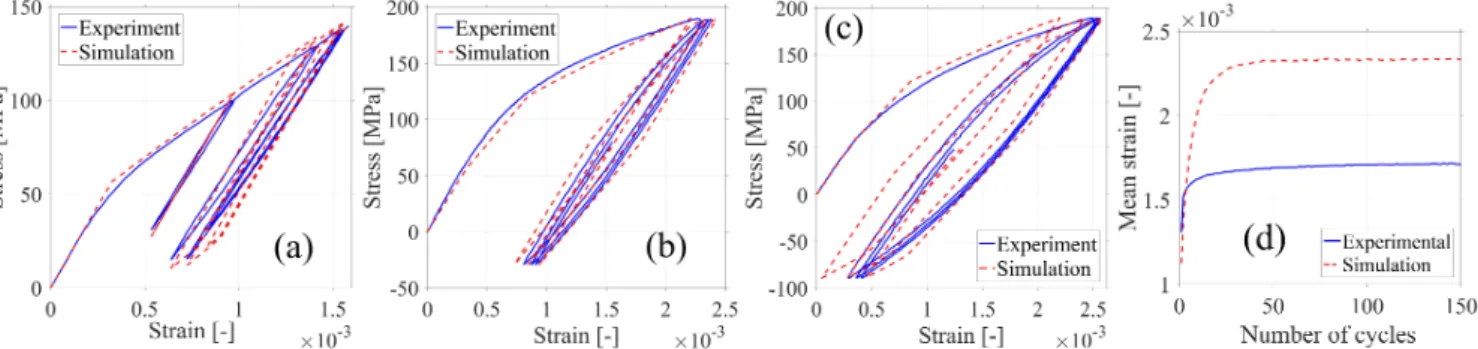
kinematic hardening law were identified by tensile tests with plastic unloads. The results show that the isotropic hardening does not exist in the domain studied. Thus, the matrix is modeled with only a kinematic hardening. Fig. 4(a) shows the experimental and simulated responses for the inter-filamentary
area with the retained σym/Cm/γm parameters.
C. Macroscopic scale and global optimization
Cyclic tests were carried out using pneumatic grips with a sufficiently short length of the strand between the grips to avoid buckling. The test was controlled in stress with a mean stress σm=80 MPa and a stress amplitude σa=110 MPa.
Stress-strain results are shown in Fig. 4(b) with the calculated response. The value of the parameters identified in the global optimization are summarized in Table IV.
D. Model validation using cyclic tests
To evaluate the robustness of the model, two independent cyclic tests were used. Fig. 4(c) displays the experimental and simulated stress-strain curves of a cyclic test performed at σm=80 MPa and σa=120 MPa. One can observe that the strain
amplitude is well predicted. However, during these tests, a plastic strain increment occurs every cycle, which is called ratchetting. Fig. 4(d) shows the evolution of the mean strain with the number of cycles for cyclic test. It can be seen that the model is able to predict the existence of such ratchetting during cyclic loading, although its level is not well described. It could be improved by adding one or more kinematic hardening terms or by modifying its constitutive law [28], at the expense of the identification cost.
V. CONCLUSION
This work presents a mechanical composite elasto-plastic modeling of MgB2 strands based on a multi-scale
characterization, an elasto-plastic calculation and a complete optimization process. The model of strand’s mechanical behavior as identified has a low computation cost, it can henceforth be used for the simulation of the mechanical response of superconducting cables under loading representative of in-service conditions, which is necessary for accurately predicting their coupled electrical response. Fig. 4. Stress-strain curve of experimental and simulated results of (a) Inter-filamentary area with plastic unloads, tension-compression cyclic test on complete strand used for (b) the identification and (c) the validation. (d) Evolution of calculated and experimental mean strain of test (c) with number of cycles.
TABLEIV
PARAMETERS OF THE STRAND MODEL
fv E (GPa) σy (GPa) b Q C γ
Outer layer 0.531 170 140 0.95 2466 0.16 638 Matrix 0.305 204 66 - - 0.29 488 Filaments 0.164 120 - - - - -
REFERENCES
[1] N. Mitchell, “Summary, assessment and implications of the ITER model coil test results,” Fus. Eng. and Design, vol. 66–68, pp. 971–993, 2003. [2] D. Ciazynski, “Review of Nb3Sn conductors for ITER,” Fus. Eng. and
Design, vol. 82, pp. 488–97, 2007.
[3] J. W. Ekin, “Strain scaling law for flux pinning in practical superconductors. Part 1: Basic relationship and application to Nb3Sn conductors,” Cryogenics, vol. 20, no. 11, pp. 611–624, 1980.
[4] H. Bajas, “Numerical simulation of the mechanical behavior of the ITER cable-in-conduit conductors,” Ph.D. dissertation, Ecole Centrale Paris, France, 2011.
[5] Kitaguchi H., Kumakura H., “Superconducting and mechanical performance and the strain effects of a multi-filamentary MgB2/Ni tape”, Supercond. Sci. Technol., vol.18 no.12, S284, 2005.
[6] K. Katagiri, K. Kasaba, Y. Shoji, D. Yamakage, T. Obara, S. Shimura, N. Koshizuka, and K. Watanabe, “Stress/strain characteristics of Cu-alloy sheath MgB2 superconducting wires,” Cryogenics, vol. 47, pp. 220–224, 2007.
[7] P. Kováč, L. Kopera, T. Melišek, M. Rindfleisch, W. Haessler, and I. Hušek, “Behaviour of filamentary MgB2 wires subjected to tensile stress at 4.2 K,” Supercond. Sci. Technol., vol. 26, no. 10, p. 105028, 2013. [8] M. Sugano, A. Ballarino, B. Bartova, R. Bjoerstad, C. Scheuerlein, and
G. Grasso, “Characterization of Mechanical Properties of MgB2 conductor for Superconducting Link Project at CERN,” IEEE Trans. Appl. Supercond., 2015.
[9] M. Sugano, A. Ballarino, B. Bartova, R. Bjoerstad, A. Gerardin, and C. Scheuerlein, “Evaluation of Young’s modulus of MgB2 filaments in composite wires for the superconducting links for the high-luminosity LHC upgrade,” Supercond. Sci. Technol., vol. 29, p. 25009, 2016. [10] N. Mitchell, “Finite element simulations of elasto-plastic processes in
Nb3Sn strands,” Cryogenics, vol. 45, no. 7, pp. 501–515, 2005. [11] D. P. Boso, M. Lefik, and B. A. Schrefler, “Homogenisation methods for
the thermo-mechanical analysis of Nb3Sn strand,” Cryogenics, vol. 46, no. 7–8, pp. 569–580, 2006.
[12] D. P. Boso and M. Lefik, “A thermo-mechanical model for Nb3Sn filaments and wires: strain field for different strand layouts,” Supercond. Sci. Technol., vol. 22, no. 12, p. 125012, 2009.
[13] D. P. Boso, “A simple and effective approach for thermo-mechanical modelling of composite superconducting wires,” Supercond. Sci. Technol., vol. 26, no. 4, p. 045006, 2013.
[14] X. Wang, Y. Li, and Y. Gao, “Mechanical behaviors of multi-filament twist superconducting strand under tensile and cyclic loading,” Cryogenics, vol. 73, pp. 14–24, 2016.
[15] N. Mitchell, A. Devred, D. C. Larbalestier, P. J. Lee, C. Sanabria, and A. Nijhuis, “Reversible and irreversible mechanical effects in real cable-in-conduit conductors,” Supercond. Sci. Technol., vol. 26, no. 11, p. 114004, 2013.
[16] A. Torre, H. Bajas, and D. Ciazynski, “Mechanical and Electrical Modeling of Strands in Two ITER CS Cable Designs,” IEEE Trans. Appl. Supercond., vol. 24, no. 3, 2014.
[17] D. Ciazynski, A. Torre, S. Li, and G. Lenoir, “Coupled Mechanical and Electrical Modeling of Nb3Sn Strand Critical Current Under Bending,” IEEE Trans. on Appl. Supercond., vol. 26, pp. 1–6, 2016.
[18] W. C. Oliver and G. M. Pharr, “An improved technique for determining hardness and elastic modulus using load and displacement sensing indentation experiments,” Journal of Materials Research, vol. 7, no. 06, pp. 1564–1583, 1992.
[19] X. Li and B. Bhushan, “A review of nanoindentation continuous stiffness measurement technique and its applications,” Materials Characterization, vol. 48, no. 1, pp. 11–36, 2002.
[20] F. Cordero, R. Cantelli, G. Giunchi, and S. Ceresara, “Search for incipient lattice instabilities in MgB2 by anelastic spectroscopy,” Phys. Rev. B, vol. 64, no. 13, p. 132503, 2001.
[21] Materials catalogue of Goodfellow. http://www.goodfellow.com/ [22] M. Fu, J. Chen, Z. Jiao, H. Kumakura, K. Togano, L. Ding, Y. Zhang, Z.
Chen, H. Han, and J. Chen, “Mechanical properties and bending strain effect on Cu–Ni sheathed MgB2 superconducting tape,” Physica C: Superconductivity, vol. 406, no. 1–2, pp. 53–57, 2004.
[23] J. Lemaitre and J.-L. Chaboche, "Mechanics of solid materials" Cambridge University Press, 1994.
[24] N. C. Van Den Eijnden, A. Nijhuis, Y. Ilyin, W. A. J. Wessel, and H. H. J. ten Kate, “Axial tensile stress–strain characterization of ITER model coil type Nb3Sn strands in TARSIS,” Supercond. Sci. Technol., vol. 18, no. 11, pp. 1523–1532, 2005.
[25] K. Osamura, A. Nyilas, M. Thoener, B. Seeber, R. Fluekiger, Y. Ilyin, A. Njihuis, J. Ekin, C. Clickner, R. P. Walsh, V. Toplosky, H. Shin, K. Katagiri, S. Ochiai, M. Hojo, Y. Kubo, and K. Miyashita, “International round robin test for mechanical properties of Nb3Sn superconductive wires at room temperature,” Supercond. Sci. Technol., vol. 21, no. 4, p. 45006, 2008.
[26] Nickel, Cobalt and Their Alloys, ASM International, Materials Park, OH, USA, 2000.
[27] Goldberg D. E., “Genetic Algorithms in search, optimization and machine learning”, Addison-Wesley Publishing Inc, no.2, 1989. [28] N. Ohno and J.-D. Wang, “Kinematic Hardening Rules for Simulation of
Ratchetting Behavior,” European Journal of Mechanics A/Solids, Vol. 13, No. 4, pp. 519–531, 1994.