HAL Id: hal-02467473
https://hal.inria.fr/hal-02467473
Submitted on 5 Feb 2020
HAL is a multi-disciplinary open access
archive for the deposit and dissemination of
sci-entific research documents, whether they are
pub-lished or not. The documents may come from
teaching and research institutions in France or
abroad, or from public or private research centers.
L’archive ouverte pluridisciplinaire HAL, est
destinée au dépôt et à la diffusion de documents
scientifiques de niveau recherche, publiés ou non,
émanant des établissements d’enseignement et de
recherche français ou étrangers, des laboratoires
publics ou privés.
From autonomous navigation to platooning in urban
context
Philippe Martinet, Benoît Thuilot, Jonathan Bom
To cite this version:
Philippe Martinet, Benoît Thuilot, Jonathan Bom. From autonomous navigation to platooning in
urban context. IARP-Workshop on Adaptive and Intelligent Robots : Present and Future, Russian
Academy of Sciences, Nov 2005, Moscou, Russia. pp.1-9. �hal-02467473�
From autonomous navigation to platooning in urban
context
Philippe Martinet
LASMEA Blaise Pascal University Clermont-Ferrand, France [email protected]
Benoit Thuilot
LASMEA Blaise Pascal University Clermont-Ferrand, France [email protected]
Jonathan Bom
LASMEA Blaise Pascal University Clermont-Ferrand, France [email protected]
Abstract— In this paper, the problem of autonomous navigation
is addressed starting from the use of RTK-GPS until the use of vision as the main sensor. Using a decoupling strategy, it is possible to control separately lateral and longitudinal control in trajectory following tasks. Recent advances in vision, make possible to localize an urban vehicle in regard with a previously recorded trajectory.
The concept of sensory memory (GPS, Vision), which tra-duces the learnt trajectory, is introduced and used to guide autonomously the vehicle. Then, an extension to vehicle platoon is described. Different kind of longitudinal control strategies are discussed : from a near to near approach, to a global strategy. Finally, in order to manage different kind of scenario which occur in a platoon context, a monitoring module is developed.
All theses aspects are currently addressed through the BODEGA (ROBEA-CNRS national interdisciplinary research program) and MOBIVIP (PREDIT3 national research program) projects.
I. INTRODUCTION
In order to reduce and suppress nuisances, linked to the saturate traffic, new alternative ”Urban Transportation Sys-tems” are under development. Some of these projects, based on urban electric vehicles, have been already developed since the mid-90’s, e.g. Praxit`ele in France [12]-[4], CarLink in the USA [22], Crayon in Japan [7]. Such systems involve the capabilities of urban vehicles to be autonomously guided in a single or platoon configuration.
To move autonomously with the best efficiency, one of the most interesting functionality appears to be the platooning of vehicles composed of a leader followed by vehicles in a single file. Nevertheless, the automatic guided vehicles need to be localized the more accurate possible in their environment. Different approaches can be envisaged. Some applications, requiring equipped infrastructures, are in developing or devel-oped: automatic vans in suspension over a guideway, thanks to Electro Magnetic forces, are described in [14], a fleet of urban shuttles detecting magnetic track integrated in the road pavement is described in [8]. The majority of Automated Highways Systems needs an equipped road with an adapted architecture as described in PATH project [10]. An alternative consists in relying on direct sensors (as cameras [5], radar [11],...), providing relative information with respect to the preceding vehicle without requiring an equipped infrastructure. Finally, mixed approaches are also investigated: in [21], the
authors combine a direct sensor (laser radar) with an inter-vehicles communication integrated in an equipped road in-frastructure transmitting data from throttle and brake actuators. Unluckily, all these solutions have drawbacks: respectively the cost and the necessity to equip an area, and/or, a too small field of perception for the considered sensor. To overcome such problems, an interesting solution is the use of RTK GPS (Real Time Kinematic Global Positioning System) sensors, which can provide in realtime vehicle localization with a centimeter accuracy. These sensors, coupled with an inter-vehicles communication, permit to share absolute localization measurements. Some results of vehicles platoon control rely-ing on this technology can be found in the literature: in [3], the authors develop particulary the GPS aspect, while in [17], the communication is studied.
This last approach was first developed in [2]: RTK-GPS sensors and inter-vehicles communication relying on WiFi technology are mounted on urban electric vehicles. Because of the problem of satellite visibility in urban context, more recently, we have started to investigate another perception system mainly based on vision data [19]. This novel approach [18] is currently under development and the first results in autonomous navigation are very promising.
One possible objective in platooning is to control vehicles velocity in order to keep either a constant cartesian distance or a constant time (see e.g. [9]) between the cars. Here, our aim is to keep a constant curvilinear distance between vehicles. The main advantage of curvilinear distance is that it agrees with the distance travelled (monotonous behavior) and is perfectly consistent when following reference paths with high curvature (which is not the case with cartesian distance).
Our platooning control design relies on nonlinear tech-niques, as in [6], instead of control approaches based on linear approximations (e.g. [15] [17]). These techniques can provide better tracking performances and allow to fully decouple longi-tudinal and lateral controls. Thanks to this decoupling feature, lateral guidance of each vehicle in the platoon can indeed be achieved independently, from its longitudinal control.
Usually, the standard approach to control a platoon is based on a local strategy, i.e. each vehicle is controlled from the unique data received from the single immediate front vehicle, see [2]. Such a local approach presents drawbacks,
like errors accumulation: the regulation errors, introduced by sensors noises, are growing from the first vehicle to the last one leading to unacceptable oscillations. To overcome these problems, inter-vehicles communication has to be considered: in [16], distance, velocity and acceleration with respect to the preceding vehicle are transmitted in order to compute the expected spacing error, and therefore to incorporate prediction in the controller. In [26], information from the immediate preceding and following vehicles are used in order to guarantee stability in tight platoon applications. We have developed a global control strategy in order to more widely capture the platoon behavior, information transmitted from the immediate front vehicle and the leader one are used to control each fleet element according to a global strategy.
The paper is organized as follows: first, modelling and theoretical concepts are addressed. Then, perception control and monitoring aspects of the work are presented. After, on one hand, full-scale experiments show the performances of a platoon composed of 2 vehicles, and, on the other hand, long platoon (10 cars) simulations are then reported.
II. MODELLING AND THEORETICAL CONCEPTS
A. Notations and Modelling
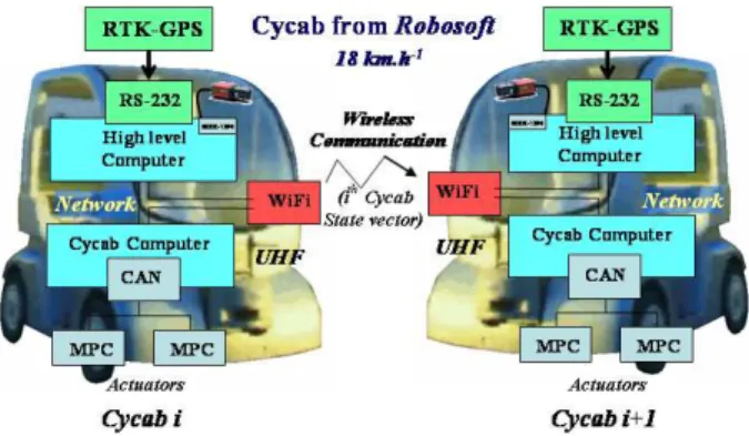
In our approach, we use a localization system (RTK-GPS or monocular vision) and inter-vehicles communication relying on WiFi technology. All the necessary equipments are mounted on urban electric vehicles called Cycabs (Fig. 1), which serve as development products in several French labo-ratories.
Fig. 1. Our experimental vehicles: Cycabs
The platoon architecture is presented on the Fig. 2. Each vehicle is equipped with an RTK-GPS (SAGITTA from Thales Navigation) and a monocular camera connected to a high level computer. A WIFI connection allows to receive the state of the platoon, and to send the state of the current vehicle. The low level control is based on a CAN architecture where two MPC555 micro-controllers pilot the heading and the longitudinal velocity of the vehicle.
1) Notations: Since Cycabs are devoted to move in urban
environments, i.e. at low speed on asphalt, dynamic modelling can be unconsidered. Kinematic model can satisfactorily de-scribe vehicle behavior, as corroborated by extensive tests done in various situations (different masses onboarded, on sloping grounds,...). In this paper, the celebrated tricycle
Fig. 2. Platoon architecture
model, validated by numerous laboratories [13] [20] [5] [23], is used to describe Cycab: the two actual front wheels are replaced by a unique virtual wheel located at the mid-distance between the actual wheels. The notations used are detailed and illustrated in Fig. 3:
Fig. 3. Model tricycle description
• C is the common reference path, defined in an absolute
frame [A, XA, YA).
• Oi is the center of the ith vehicle rear axle. • Mi is the closest point on C to Oi.
• si is the curvilinear coordinate of point Mi along C, it
corresponds to the distance covered along C by vehicle i.
• c(si) denotes the curvature of path C at Mi, and θc(si)
stands for the orientation of the tangent to C at Mi, with
respect to frame [A, XA, YA).
• θi is the heading of ithCycab at point Oi, with respect
to frame [A, XA, YA).
• θ˜i= θi− θc(si) denotes the angular deviation of the ith
vehicle with respect to C.
• yi is the lateral deviation of the ith vehicle with respect
to C.
• δi is the orientation of the ith vehicle front wheel with
respect to its centerline.
• L is Cycab wheelbase.
• vi is the ith vehicle linear velocity at point Oi.
• n is the number of vehicles in the platoon, so (i < n).
2) Modelling: The vector (si, yi, ˜θi) describes the state of
the ithvehicle. It can be inferred online by comparing vehicle absolute localization (provided e.g. by a RTK-GPS sensor) to
the reference path. The celebrated tricycle model is (see [20], [5], [23]): ˙si= vi1−ycos ˜ic(sθii) ˙yi= visin ˜θi ˙˜θi= vi ³ tan δi L − c(si) cos ˜θi 1−yic(si) ´ (1)
Lateral and longitudinal control objectives are to bring and maintain yi and ˜θi to 0, by means of δi, and the gap between
cars to a fixed value d, by means of vi. It is considered
that: yi 6= c(s1i) (i.e. vehicles are never on the reference path
curvature center). In practical situation, if the n vehicles are well initialized, this singularity in model (1) is never met.
B. Theoretical concepts
This section presents the conventional general navigation scheme and the adaptation we have done in order to take into account the imprecise map and the dynamic aspect of the environment.
1) General scheme for navigation: A general and
well-known scheme for navigation is given by Fig. 4. The main concept uses the ability of the navigation system to present two levels :
• End user level : the user defines the mission, and the system elaborates an ordered set of reference trajecto-ries. A specific module schedules the different reference trajectories during the execution.
• Execution level : The obstacle avoidance module permits to modify the reference trajectory in order to take into account the static and dynamic evolution of the scene. A localization module allows to extract the necessary information about the current vehicle (or the whole set of vehicle in case of platoon) in regard with the reference trajectory. The control module has in charge the execution of the trajectory following task. Finally, the FDIR module
(Failure Detection , Isolation and Recovery) monitors the
execution of the whole system in order to prevent from failures, and from different situations which can occur. In addition, on line reconfiguration of the whole system can be done using such module.
Fig. 4. General navigation scheme
This conventional system is efficient when the map of the environment is known with a centimeter accuracy for precise
navigation. Unfortunately, this hypothesis is difficult to guarantee : the map remains unprecise. So, instead of having a global view of the navigation system, we have prefered to use of a local view where each reference trajectory is defined in the sensor frame. This approach prevents from global errors of the map. As we have selected a local behaviour and a closed loop approach, the trajectory following task can be realized in good condition.
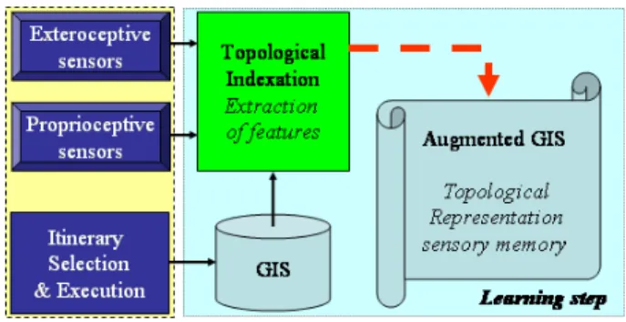
2) Learning step : Concept of sensory memory: In order to
build a Topological representation of the environment, taking profit of the local perception of the reference trajectory, we have proposed to develop a learning step as represented in Fig. 5. During the learning step, the vehicle is driven by a human and acquires an ordered set of sensor information coming from proprioceptive and exteroceptive sensors. Theses information are stored (using the topological representation extracted from a GIS system) and represent the sensory memory of the reference trajectory. At the end, all the learnt trajectories are available in an Augmented GIS module.
Fig. 5. Learning step : Sensory memory
3) Localization step: Completing the learning step, the
system is ready to perform any autonomous displacements. After itinerary selection, a set of reference learnt trajectories are ready for execution. A localization module using the same sensors (used during the learning step), computes the necessary information in order to provide the control scheme. In the presented work, theses information are : the lateral deviation yi, the angular deviation ˜θi, and the local datas
of the reference trajectory (curvilinear abscissa si, local
curvature c(si))
III. PERCEPTION,CONTROL AND MONITORING
In this section we will successively present the different aspects relating to perception, control and monitoring.
A. Perception
For the perception aspect, we are currently addressing three main ways. The first one use an RTK-GPS (Real-Time Kine-matic Global Positioning System) sensor in order to deliver an absolute localization of each vehicles. The second is a pure vision based approach and provide a relative localization of
Fig. 6. Localization
each vehicles, and the third one is supposed to take advantages of each approach by using data fusion techniques. We will present here only the two first ones (the last one is under development).
1) Absolute Localization using RTK-GPS system: The RTK
GPS receiver is a Sagitta unit from Thales Navigation. It provides position measurements at a 10Hz sampling frequency, with a 2cm accuracy. The GPS reference station has been located on a 15m-height building. Each Cycab is equipped with a unique GPS sensor located on the roof of the vehicle straight up the mid-distance between the rear wheels. The radio receiver is in front of the vehicle. So, during the learning step (Fig. 7) the reference trajectory is extracted and stored in the GPS sensory memory. During the autonomous displace-ment, RTK-GPS sensor delivers the absolute localization, and the localization module is able to compute the relative position of the vehicle. To be available, GPS system needs at minimum the visibility of four satellites in any points of the reference trajectory, and at any time. Depending on the constellation, the quality and integrity of the signals are not always insured. Thanks to the news systems using the geostationary satellite EGNOS (for Europe) to improve theses points.
Fig. 7. GPS based memory
2) Relative Localization using vision system: Another
solution is to design a system which can be embedded on the vehicle and offers the same kind functionalities as the GPS system does. Two years ago, we started to investigate a new approach based on a simple monocular camera [19].
During the learning step (Fig. 8), a camera acquires a
Fig. 8. Vision based memory
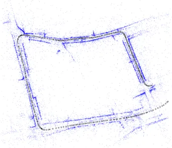
video sequence along a human driven trajectory. Then, a post processing algorithm extracts relevant information (here this is 3D points of the scene) from the video sequence in order to reconstruct the reference trajectory (using a bundle adjustment technique) and store it in an ordered way of key features. In on line step, the local extracted features are compared to the reference one in order to perform features matching, and then the localization procedure can be achieved. Fig. 9 represents an example of the visual memory (reference trajectory) learnt by vision in a real city center. The blue dots correspond to the 3D points of the environment, and small black squares represent the corresponding localization (obtained by 3D reconstruction) of the camera during the learning step.
Fig. 9. An example of Vision based memory of a reference trajectory
B. Control
Our platooning control design relies on nonlinear tech-niques, as in [6]. These techniques can provide better tracking performances and allow to fully decouple longitudinal and lateral controls. Thanks to this decoupling feature, lateral guidance of each vehicle in the platoon can indeed be achieved independently, from its longitudinal control.
1) Chained system: As developed in [20], one way to build
a nonlinear suitable control law for mobile robots is to turn their equations into chained form (as it has been done in [24]). In dimension 3 (as expected in our application), such a system is given by : ˙a1i= m1i ˙a2i= a3im1i ˙a3i= m2i (2) where A = (a1i, a2i, a3i)T = Θ(si, yi, ˜θi) and M =
(m1i, m2i)T = Υ(vi, δi) are respectively the state and control
vectors. One can check that such a system is almost linear: just replace time derivation by a derivation with respect to a1i.
It leads to system 3 (with notation (aji)0= dadaji1i).
a0 1i= 1 a0 2i= a3i a0 3i= m3i= mm2i1i (3)
The following state transformation a1i= si a2i= yi a3i= tan ˜θi(1 − yic(si))
is here proposed in association with control transformation given by : m1i= vi1−ycos ˜ic(sθii) m2i= dtd ³ (1 − yic(si)) tan ˜θi ´
The new system 3 becomes in a linear form with longitudi-nal and lateral decoupling properties for trajectory following tasks.
2) Lateral Control: Path following can be now easily
addressed : in view of the state transformation, the regulation of yi and ˜θi is equivalent to regulation of a2i and a3i. So, the
following auxiliary control law
m3i= −kd a3i− kp a2i (4)
provides the equation of a second order system :
a00
2i+ kda02i+ kpa2i = 0 (5)
which can be tuned using the gains (kp, kd) to specify a
settling distance (instead of a settling time). The following trajectory task is well achieved not depending on the value of the longitudinal velocity (as long as this value is not zero).
Such kind of lateral control techniques have been evaluated using both the GPS based memory in [23] and also the vision based memory in [18].
3) Longitudinal Control: The decoupling capabilities of
the presented approach allows to be more flexible when considering a single vehicle or a platoon of vehicles. Indeed, it allows the user or a global system to impose a particular longitudinal velocity in single mode. In platoon mode the inter-distance between vehicle can be regulated through different control strategies.
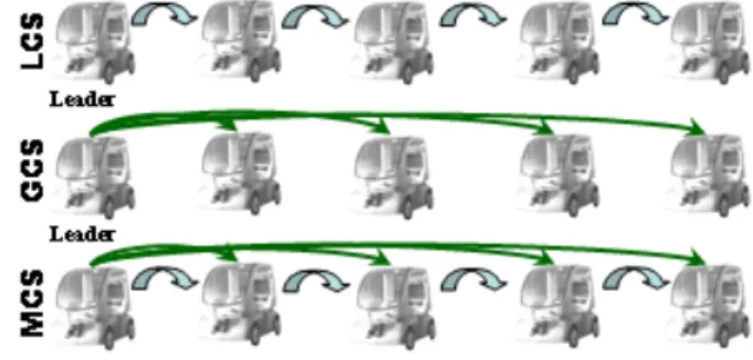
Fig. 10. Longitudinal control strategies
Fig. 10 illustrates the different control strategies which can be studied. The first one, called LCS is a local control strategy where the longitudinal control is based on a near to near approach. The second one, called GCS, is a global control strategy where the longitudinal control is based on the leader. Each of theses solutions have drawbacks ([2] and [1]). This is the reason why, we have prefered to develop a third one, called MCS, which is a mixed strategy taking profit of advantages of both approaches depending on the context evolution.
So, we have proposed to regulate a new longitudinal error function (see Fig.11) defines by :
xi+1= σi+1e1i+1+ (1 − σi+1)eii+1 (6)
where
• e1i+1 represents the curvilinear distance between the cur-rent vehicle and the leader. In the GCS approach, this error is regulated to a desired distance i.d.
• eii+1 represents the curvilinear distance between the cur-rent vehicle and the nearest front vehicle. In the LCS approach, this error is regulated to a desired distance d.
• σi+1 is a sigmoid function and gives more or less predominance at each error depending on the context.
In order to design σi+1, security distance dsis introduced as
the minimal curvilinear distance that always must be observed between 2 vehicles. When distance between vehicles i and i+1 is close to this limit, collision risk is important. Therefore, local approach must prevail over the absolute reference one.
σi+1 must then be close to 0 when eii+1 is close to −d + ds.
On the contrary, when inter-vehicles distance is close to d, absolute reference approach can be safely used. σi+1 must
then be close to 1 when eii+1is close to 0. Such a commutation can be obtained via the sigmoid function (7):
σi+1(zi+1) = 0.5 µ 1 − e−azi+1 1 + e−azi+1 + 1 ¶ (7)
driven by variable zi+1 defined by:
zi+1= eii+1+
d − ds
2
Parameter a = 2.5 is chosen to ensure the shape on Fig. 12.
Fig. 12. Mode commutation using a sigmoid function
From the control point of view, we impose an exponential decrease of the new error function ( ˙xi+1 = −kxi+1). Then,
the longitudinal control law can be expressed by :
vi+1= cos ˜θ 1−yi+1 c(si+1)
i+1[1+A(zi+1)(s1−si−id+d)] ³
σi+11−yv1cos ˜1c(sθ11)
+ [1 − σi+1+ A(zi+1)(s1− si+ d − id)]1−yvicos ˜ic(sθii)
+ kxi+1)
(8) where A(zi+1) = (1+ea e(−a zi+1)(−azi+1))2.
C. Monitoring
Control (8) presents one singularity, namely 1 + (s1− si− (i − 1)d)A(zi+1) = 0. However, it
corresponds to a very special configuration of the first, the ith and the (i + 1)th vehicles, which is not expected to be met in practical situation. Moreover, if this configuration was met, vi+1 would increase to reach very large values that
would then be corrected by monitoring.
Saturation problems can clearly appear: e.g. if the cars are too far, large accelerations, and so high velocities, can occur. In order to achieve passengers security and comfort, some constraints have to be satisfied. First, vehicles velocities have to be bounded:
0 ≤ vi+1≤ vmax (9)
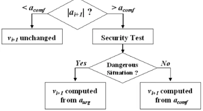
This ensures that vehicles never move back nor exceed a desired velocity. It can be done by using and adaptive gain in the longitudinal control law. Secondly, if vehicle i + 1 is far behind vehicle i, or if vehicle i presents an odd behavior (e.g. if it stops abruptly), control law (8) may then lead to very large accelerations/decelerations, very unpleasant to passengers aboard. Therefore, the monitoring scheme shown on Fig. 13 has been introduced, with the aim to privilege passengers comfort, as far as their security can be guaranteed.
Fig. 13. Monitoring security and comfort
More precisely, the notation acomfon Fig. 13 stands for the
maximum acceleration/deceleration comfortable to a passenger aboard. Then, if the acceleration/deceleration of vehicle i + 1, denoted ai+1, is superior to that value, a security test is
performed:
• the case ai+1 > acomf > 0 occurs when vehicle i + 1
is far behind vehicle i. In such a situation, ai+1 can be
limited to acomf without any collision risk.
• the case ai+1 < −acomf < 0 occurs if vehicle i stops
abruptly. In such a situation, collision risks have to be investigated. To this aim, the distance covered by vehicle
i + 1, if it was stopped with a deceleration −acomf, is
first computed, and its final inter-distance with vehicle i is derived (the worst case, i.e. vehicle i is stopped, is here assumed).
– if this inter-distance is superior to ds, then ai+1 can
safely be limited to −acomf.
– in the other case, the deceleration (denoted −aurg)
leading to a projected inter-distance equal to ds is
computed, and ai+1 is limited to that value.
Pas-sengers security is privileged with respect to their comfort.
When computing the final inter-distances with constant decelerations (−aurg or −acomf), delays introduced by
actuator features and transmission latencies are taken into account.
IV. RESULTS
This section is divided into two parts: first, experimental results involving two vehicles validate control law (8) and
monitoring. Secondly, simulations with larger platoons com-pare capabilities of LCS and GCS.
A. Experimentation
Several experiments have been carried out at ”Campus des C´ezeaux”, in Clermont-Ferrand area. These experiments involve only two vehicles, therefore σi+1 has no influence
as the immediate front car and the leader are the same. However, experiments with more vehicles are planned, since our lab will soon be equipped with additional vehicles. Only experimentations related to GPS base memory are reported here.
1) Experimental Vehicle: Experimental vehicles, named
Cycab, are depicted on Fig. 1. Their small dimensions (length 1.90m, width 1.20m) are advantages for the urban traffic. These vehicles are entirely under control computer. The used kinematic configuration is the same as those of a car-like vehicle. Its maximum speed is vmax = 18km/h. In our
experiments, a personal computer is added in each Cycab. This high-level computer collects information received from RTK GPS, mounted by serial link, and from front vehicles, via WiFi. The used RTK GPS receiver provides measurements at a 10HZ sampling frequency, with a 2cm accuracy. The steering values and the vehicle velocities computed by control laws are transmitted to the Cycab computer by an Ethernet network and reach the MPC555 micro-controllers by CAN. The used kinematic configuration is the same as the one of a car-like vehicle. Its maximum speed is 5m/s. The mounted RTK GPS receiver provides measurements at a 10Hz sampling frequency, with a 2cm accuracy. The communication between cars is ensured via WiFi.
2) Experiment: The gains of the lateral control law are
tuned to impose that lateral deviation converges to 0 within 15m. Parameters of the longitudinal law are set to k = 0.6,
vmax= 4m/s, acomf = 1m/s2(ensued from studies reported
in [25]), d = 8m and ds= 6.50m. In practical situation, we
could imagine that the leader is pulling a trailer, and that collision occurs if the inter-distance is inferior to ds.
Fig. 14. Reference Trajectory : lateral control performances
Fig.14 illustrates the shape of the reference trajectory. For each vehicles, lateral deviation are less than 3cm in straight line and less than 10cm in bend.
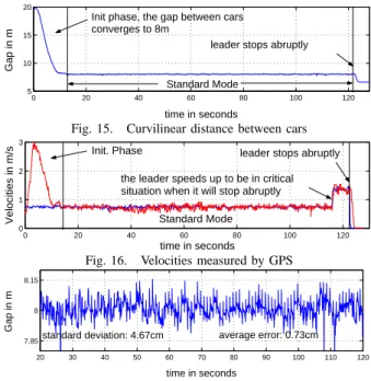
The experiment reported on Fig 15 can be divided into three main parts. First, the hooking is tested: at initial time, the space between the cars is close to 20m. Thanks to the monitoring, the hooking appears smooth and comfortable (acceleration saturated at acomf and v < vmax, see Fig. 16). In a second
phase, the longitudinal standard law performances are scanned. Once the follower is hooked, the gap is equal to d with a satisfactory standard deviation of 4.7cm and a mean error inferior to 1cm (Fig. 17). Finally, the security of the law, in
0 20 40 60 80 100 120 5 10 15 20 time in seconds Gap in m
Init phase, the gap between cars converges to 8m
leader stops abruptly Standard Mode
Fig. 15. Curvilinear distance between cars
0 20 40 60 80 100 120 0 1 2 3 time in seconds Velocities in m/s Init. Phase Standard Mode
leader stops abruptly the leader speeds up to be in critical situation when it will stop abruptly
Fig. 16. Velocities measured by GPS
20 30 40 50 60 70 80 90 100 110 120 7.85 8 8.15 time in seconds Gap in m
standard deviation: 4.67cm average error: 0.73cm
Fig. 17. Zoom on curvilinear distance in standard mode
critical situation is investigated. Preliminary, the leader reaches a higher velocity in order to position the platoon in a critical situation when it stops abruptly. As the security can not be achieved with a deceleration equal to −acomf, an urgency
deceleration equal to −1.2m/s2 is computed and applied, see Fig. 18 and Fig. 19. This experiment demonstrates satisfactory performances of the control law (8) and monitoring (comfort mode is tested at the beginning and security mode at the end).
117 118 119 120 121 122 123 124 125 126 127 128 6.5 7 7.5 8 8.5 time in seconds Gap in m security distance
leader stops abruptly
Standard Mode
Stop Phase
from this moment, the 2 cars are stopped
Fig. 18. Curvilinear Distance between cars in stop phase
117 118 119 120 121 122 123 124 125 126 127 128 0 0.5 1 1.5 time in seconds Velocities in m/s Leader Velocity Standard Mode Stop phase with urgent deceleration
at this time, leader stops abruptly
Follower Velocity
B. Simulations
In this part, GCS is compared with a classical LCS. The common scenario is a path following to be achieved, by a 10 vehicles long platoon, at a constant velocity of 2m/s (fixed by the leader). In order to simulate LCS, the parameter σi+1 is
simply set to 0 in control law (8). All parameters are identical in LCS and GCS simulations (they are the same as in the experiment). Finally GPS features are introduced via a white noise with a standard deviation of 10cm added to position measurements. GPS sensors used in previous experiment have a 2cm accuracy, but are quite expensive. When numerous vehicles have to be equipped, decimeter GPS appears more realistic. Moreover, less accurate sensors reveal more clearly the advantages of GCS over LCS.
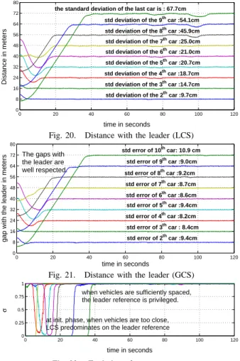
0 20 40 60 80 100 120 0 8 16 24 32 40 48 56 64 72 80 time in seconds Distance in meters
the standard deviation of the last car is : 67.7cm
std deviation of the 2th car :9.7cm std deviation of the 3th car :14.7cm std deviation of the 4th car :18.7cm std deviation of the 5th car :20.7cm std deviation of the 6th car :21.0cm std deviation of the 7th car :25.0cm std deviation of the 8th car :45.9cm std deviation of the 9th car :54.1cm
Fig. 20. Distance with the leader (LCS)
0 20 40 60 80 100 120 0 8 16 24 32 40 48 56 64 72 80 time in seconds
gap with the leader in meters
The gaps with the leader are well respected. std error of 10th car: 10.9 cm std error of 2th car :9.4cm std error of 3th car : 8.4cm std error of 4th car :8.2cm std error of 5th car :9.4cm std error of 6th car :8.6cm std error of 7th car :8.7cm std error of 8th car :9.2cm std error of 9th car :9.0cm
Fig. 21. Distance with the leader (GCS)
0 20 40 60 80 100 120 0 0.25 0.5 0.75 1 time in seconds σ
at init. phase, when vehicles are too close, LCS predominates on the leader reference
when vehicles are sufficiently spaced, the leader reference is privileged.
Fig. 22. Evolution of parameter σi+1
The first simulation presents LCS. In order to highlight errors accumulation, the gap between each vehicle and a common reference point in the platoon, i.e. the platoon leader, is depicted on Fig. 20. The main drawbacks of LCS appear then clearly: the distance to the leader presents a standard deviation of 9.7cm for the first follower, when it is 67.7cm for the last one. The situation gets even worse in tight turns: when the last vehicle is in a bend, at t = 95s see Fig. 20, the maximum error recorded is 2.80m.
In the second simulation, when GCS is used, these draw-backs disappear, see Fig. 21: each follower is subjected to
errors of the same order of magnitude. The standard longitu-dinal deviations of each vehicle are close to 10cm (9.5cm for the first follower and 10.9cm for the last one, i.e. the error is simply equal to the introduced GPS noise, see Fig. 23). Therefore, these simulations demonstrate that GCS surmounts the limitations of LCS. Moreover, when observing parameter
σi+1 in the Init. phase (Fig. 22), it can be seen that the
platooning laws commute progressively from LCS (when inter-vehicles distance is small) to a control with respect to an absolute reference (when the gap is close to d).
Vehicle 2 3 4 ... 8 9 10
LCS 9.7 14.7 18.7 ... 45.9 54.1 67.7
GCS 9.5 8.4 8.2 ... 9.2 9.0 10.9
Fig. 23. Standard deviation (in cm) according the strategy
Platoon security is therefore ensured (by LCS) when cars are close to each other, and in standard mode, high regulation performances are obtained (by the absolute reference). The skill to adapt the longitudinal error at the met situation is clearly demonstrated.
V. CONCLUSION
In this paper, we have presented some work done in the french national research context mainly in the ROBEA-CNRS BODEGA project, and in the PREDIT3 MOBIVIP project. The main goals of such projects are to demonstrate the ability of Intelligent Transportation System to supply autonomous services (Car Sharing in single or platoon mode) for the end user in city centers.
We have studied a complete system able to perform some autonomous following tasks in single and platoon mode using a navigation scheme which takes into account the imprecise part of the GIS map. Using a learning step to acquire a set of reference trajectories, we built an augmented GIS to order the trajectories using a topological description of the environment. Localization is performed in regard with the reference trajectories. We have designed nonlinear control laws whose main property is to decouple lateral and longitudinal behaviour. A monitoring module has been developed and takes in charge security, comfort, and system limitations aspects.
Validation have been realized both in real (up to 2 cars) and in simulation (up to 10 cars). In the real case, we have used RTK-GPS sensor in order to extract the local state of each vehicle involve in the platoon. From the perception point of view, as visibility of satellite becomes a difficult problem in city center, we have started to evaluate a novel solution using a simple monocular camera. The current results [18] show the validity of such approach (lateral error is less than 10cm in straight line, and less than 35cm in bend). Lateral control using this novel approach is ensured with a 10cm accuracy.
The next research steps will concern control, multi-sensor perception, monitoring, and real validation with more cars.
In control, it remains two main critical points to study. The first one concerns the ”point stabilization problem”. As
vehicles are non holonomous robots, this point remains an open problem in control theory. The second one concerns the platoon modelling : it would be interesting to consider platoon as a multi-robot system under constraints.
We start to develop a multi-sensor approach using a low cost DGPS sensor, one monocular camera and some pro-prioceptive sensors. Data fusion techniques will be adapted to our particular application, knowing that we are not only interested to localize the current vehicle, but also to compute the localization of each cars involves in the platoon.
In the current version of our navigation system, we have not yet develop the obstacle avoidance module. It would be interesting to have one, and to extend the functionalities of the monitoring module in order to take into account an exhaustive set of states for the platoon.
Finally, we have already two cars equipped, and planed to buy three more. Real experiment (up to 5 or 6 cars) will be done in 2006 in order to validate our complete system.
ACKNOWLEDGMENT
The authors would like to thank F. Marmoiton for his technical support in the all set of real experimentation.
REFERENCES
[1] J. Bom, B. Thuilot, F. Marmoiton, and P. Martinet. A global control strategy for urban vehicles platooning relying on nonlinear decoupling laws. In 22nd International Conference on Intelligent Robots and Systems (IROS’05)), pages 1995–2000, Edmonton (Canada), August 2005.
[2] J. Bom, B. Thuilot, F. Marmoiton, and P. Martinet. Nonlinear control for urban vehicles platooning, relying upon a unique kinematic GPS. In 22ndInternational Conference on Robotics and Automation (ICRA’05), pages 4149–4154, Barcelona (Spain), April 2005.
[3] M.E. Cannon, C. Basnayake, S. Crawford, S. Syed, and G. Lachapelle. Precise GPS sensor subsystem for vehicle platoon control. In Conference ION GPS/GNSS, pages 213–224, Portland OR (USA), September 2003. [4] P. Daviet, S. Abdou, and M. Parent. Platooning for vehicles and auto-matic parking by scheduling robotic actions. In International Symposium on Robotics and Manufacturing (WAC’96), Montpellier (France), 1996. [5] P. Daviet and M. Parent. Platooning for small public urban vehicles. In 4thInternational Symposium Experimental Robotics (ISER’95), pages 345–354, Stanford, CA (USA), July 1995.
[6] A. De Luca, G. Oriolo, and C. Samson. Feedback control of a nonholonomic car-like robot. In Robot Motion Planning and Control, J.P. Laumond eds, volume 229 of Lectures Notes in Control and Information Sciences, pages 171–253, Springer-Verlag, 1998.
[7] P. Evans. New energy sources for the car : how toyota sees the future. Energy News (Australian Institute of Energy), 18(2), June 2000. [8] D. Gillet and T. Chevroulet. BURST : Bright urban system for
transportation. In 2ndInternational Workshop on European Scientific and Industrial Collaboration (WESIC’99), Newport (Wales), Sept. 1999. [9] A. Girault and S. Yovine. Stability analysis of a longitudinal control law for autonomous vehicles. In IEEE Conference on Decison and Control (CDC’99), volume 4, pages 3728–3733, Phoenix AR (USA), December 1999.
[10] R. Horowitz and P. Varaiya. Control design of an automated highway system. Proc. IEEE, 88(7):913–925, July 2000.
[11] H. Kuroda, S. Kuragaki, T. Minowa, and K. Nakamura. An adaptive cruise control system using a milimeter wave radar. In IEEE Inter-national Conference on Intelligent Vehicles (IV’98), volume 1, pages 168–172, Stuttgart (Germany), October 1998.
[12] C. Laugier. Towards autonomous vehicles for future intelligent trans-portation systems. In Proc. 6th Conference of Italian Association in Artificial Intelligence, pages 251–258, Padova (Italy), Sept. 1998. [13] J.P. Laumond, editor. La Robotique Mobile. Hermes Science, Paris,
September 2001.
[14] M3 Team. The M3urban transportation system. FTA Project Report MA-26-7077, MagneMotion Inc., Acton, MA (USA), January 2003. [15] H. Makela, P. Kaarmila, and K. Koskinen. Convoy navigation. In 3rd
IFAC Conference on Intelligent Autonomous Vehicles (IAV’98), pages 31–36, Madrid (Spain), March 1998.
[16] T.S. No, K.-T. Chong, and D.-H. Roh. A Lyapunov function approach to longitudinal control of vehicles in a platoon. IEEE Transactions on Vehicular Technology, 50(1):116–124, January 2001.
[17] M. Ohtomo, R. Kimura, S . Fukushima, and N. Fujii. Automatic following system utilizing vehicle-to-vehicle communication. In IEEE International Conference on Intelligent Vehicles (IV’98), volume 2, pages 381–384, Stuttgart (Germany), October 1998.
[18] E. Royer, J. Bom, M. Dhome, B. Thuilot, M. Lhuillier, and F. Mar-moiton. Outdoor autonomous navigation using monocular vision. In 22nd International Conference on Intelligent Robots and Systems (IROS’05)), pages 3395–3400, Edmonton (Canada), August 2005. [19] E. Royer, M. Lhuillier, M. Dhome, and T. Chateau. Towards an
alter-native GPS sensor in dense urban environment from visual memory. In British Machine Vision Conference, volume 1, pages 197–206, Kingston (England), September 2004.
[20] C. Samson. Control of chained systems: application to path following and time-varying point stabilization of mobile robots. IEEE Transactions on Automatic Control, 40(1):64–77, January 1995.
[21] Y. Seto and H. Inoue. Development of platoon driving in AHS. JSAE Review, 20(1):93–99.
[22] S. Shaheen, K. Wipyewski, C. Rodier, L. Novick, M.A. Meyn, and J. Wright. Carlink II: a commuter carsharing pilot program final report. PATH Research Report UCB-ITS-PRR-2004-23, University of California, Berkeley (USA), August 2004.
[23] B. Thuilot, J. Bom, F. Marmoiton, and P. Martinet. Accurate automatic guidance of an urban electric vehicle relying on a kinematic GPS sensor. In 5thIFAC Symposium on Intelligent Autonomous Vehicles (IAV’04), Lisboa (Portugal), July 2004.
[24] B. Thuilot, C. Cariou, P. Martinet, and M. Berducat. Automatic guidance of a farm tractor relying on a single cp-dgps. Autonomous Robots, 13(1):53–71, 2002.
[25] TranSafety Inc. Simulated on-the-road emergencies used to test stop-ping sight distance assumptions. Road Management and Engineering Journal, July 1997.
[26] Y. Zhang, E.B. Kosmatopoulos, P.A. Ioannou, and C.C. Chien. Au-tonomous intelligent cruise control using front and back information for tight vehicle following maneuvers. IEEE Transactions on Vehicular Technology, 48(1):319–328, January 1999.