Publisher’s version / Version de l'éditeur:
Construction Technology Update, 2013-07-01
READ THESE TERMS AND CONDITIONS CAREFULLY BEFORE USING THIS WEBSITE.
https://nrc-publications.canada.ca/eng/copyright
Vous avez des questions? Nous pouvons vous aider. Pour communiquer directement avec un auteur, consultez la première page de la revue dans laquelle son article a été publié afin de trouver ses coordonnées. Si vous n’arrivez pas à les repérer, communiquez avec nous à [email protected].
Questions? Contact the NRC Publications Archive team at
[email protected]. If you wish to email the authors directly, please see the first page of the publication for their contact information.
For the publisher’s version, please access the DOI link below./ Pour consulter la version de l’éditeur, utilisez le lien DOI ci-dessous.
https://doi.org/10.4224/21268873
Access and use of this website and the material on it are subject to the Terms and Conditions set forth at
Window installation details for effective sealing practice
Lacasse, M. A.; Armstrong, M. M.
https://publications-cnrc.canada.ca/fra/droits
L’accès à ce site Web et l’utilisation de son contenu sont assujettis aux conditions présentées dans le site LISEZ CES CONDITIONS ATTENTIVEMENT AVANT D’UTILISER CE SITE WEB.
NRC Publications Record / Notice d'Archives des publications de CNRC:
https://nrc-publications.canada.ca/eng/view/object/?id=2dd6662e-ae5a-47e2-8734-699a57de245f https://publications-cnrc.canada.ca/fra/voir/objet/?id=2dd6662e-ae5a-47e2-8734-699a57de245f
Window Installation Details
for Effective Sealing Practice
The effects of inadvertent water entry at windows are well known: water can damage interior fi nishes and in the case of wood-frame construction, may lead to wood rot or the formation of mould in the wall assembly. The installation of a window in an adequately prepared opening in which a sill pan and back dam have been installed should be straightforward provided measures are taken to:
(1) consider the installation of a sill fl ashing membrane and the proper lapping of fl ashing layers,
(2) include a drainage gap at the window sill, and
(3) ensure that there is continuity of both the thermal barrier and air barrier to the window component.
A description of such window installation features is the focus of a previous Update, No. 76 – Window Sill Details for Effective Drainage of Water (http://archive.nrc-cnrc.gc.ca/eng/ ibp/irc/ctus/ctus-n76.html).
This current Update focuses on elements related to airtightness. It explains how the degree of airtightness and the location of the plane of airtightness of the wall-window interface affect water entry. It provides design details that ensure the continuity of the plane of airtightness at the wall-window interface.
Response of Wall-Window Interface to
Wind-Driven Rain
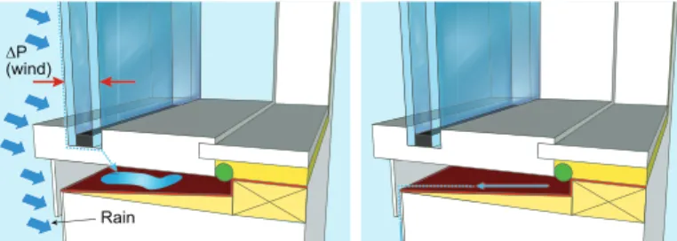
Rainwater may enter because of defi ciencies in the window components, either inherent or after the window has “aged.” When water is blown to the window (Figure 1a), the risk of entry at any defi ciency increases. It is known that water may
enter small openings due to the actions of gravity, capillary forces, or pressure differences brought about by wind action. Water entering a defective window or along the perimeter interface between the window and the cladding may fi nd its way into the wall assembly and eventually cause damage. Water reaching the sill must be drained (Figure 1b) because if left stagnant it may lead to the formation of mould.
Wind blowing on the exterior of a building obviously brings rainwater to the windows and to the wall-window interface. It also gives rise to pressure differences (ΔP) across the assembly. The magnitude of the pressure difference is a function of the wind speed and interior pressure conditions; higher wind speeds yield greater pressure differences. Hence windows are more vulnerable to water entry during storms when wind-driven rain loads are largest. Openings along the wall-window interface (e.g., gaps in the sealant behind the window fl ange, gaps in the seal between the glazing and the window sash, or defects in the window frame) may permit the passage of air and water. If water is present at an opening through which air may pass, and there is a pressure difference, water will be driven through it. The rate of entry will be dependent on
An effective and durable window installation demands good airtightness and proper water management. This Update
explains how the degree of airtightness and the location of the plane of airtightness of the wall-window interface affect
water entry. It is the second in a series of Updates presenting results from studies of window installation details.
TECHNOLOGY UPDATE
No. 80, July 2013
¨P (wind)
Rain
Figure 1 (a). Side section of a window with mounting fl anges illustrating water entry at the base of the window and collection at sill; (b) Water accumulating at the sill must be drained.
the size of the opening and the pressure difference across it. Pressure equalization is the key to preventing water entry and promoting effective drainage. Ideally the pressure in the wall-window interface (the gap between the window frame and rough opening) and the rough sill must be equal to the pressure at the exterior of the wall (caused by wind). This will eliminate driving pressures that force water to enter across the window installation, and also eliminate any pressure that may impede drainage from the sill area.
To achieve pressure equalization, both the exterior and interior airtightness details must be considered:
(1) Airtightness of the window – A leaky window will not
only allow air and water to enter, but will also contribute to heat loss or gain.
(2) Air leakage behind the fl ange – The air leakage behind the window fl ange will depend on how closely the fl ange abuts to the backup wall, whether a self-adhered fl ashing membrane is used to seal the fl ange, or sealant is used behind the fl ange. A tightly sealed fl ange may prevent water entry when fi rst installed – but only if there are no imperfections in the seal or window – however, it can result in a high pressure difference between the exterior and rough opening that will not be able to effectively manage water entry should a defect appear.
(3) Continuity of the interior air barrier – The window
frame must be sealed continuously to the air barrier at the interior window perimeter; an imperfect air barrier can allow the rough opening pressure to equalize with the interior air pressure, thereby creating a greater pressure difference across the window fl ange and a heightened risk to water entry along this seal.
NRC Construction Research
on Window Installation Details
As was reported in Update No. 76 (http://archive.nrc-cnrc. gc.ca/eng/ibp/irc/ctus/ctus-n76.html), NRC Construction undertook research to investigate the effectiveness of various wall-window interface details for managing rainwater. The robustness of specifi ed window installations relevant to residential construction was assessed by considering what occurs when windows leak, when jointing products at the window interface fail, or when the installation has reduced airtightness. Laboratory testing was conducted on wall-window interface details incorporating vinyl windows with mounting
driven rain loads. These test loads match those of signifi cant rainfall events of 5, 15 or 30 minutes duration that might occur every 10 to 30 years.
Tests on windows that were functional and operated as expected (not defective) showed that a well- sealed fl ange (e.g., with a full bead of sealant behind the fl ange) was unlikely to greatly affect water entry into the rough opening – even when the interior air barrier was leaky. However, in the case of an assembly containing a defective window, an increase in water entry to the sill was observed as well as reduced drainage from it. Increased water entry and reduced drainage resulted from airtightness details that increased the pressure difference across the fl ange, specifi cally placing sealant behind the fl ange and a leaky interior air barrier.
Window airtightness
and watertightness
The airtightness and watertightness of windows
are both rated according to procedures given
in the CSA A440 Standard. Ratings of A1 (least
airtight) to A3 (most airtight) are given based on
the results of standardized air leakage tests.
Watertightness ratings, obtained from standard
watertightness testing, relate to the pressure at
which water entry is just observed; values range
between of B1 to B7.
Based on such ratings, appropriate windows
should be selected to match the average wind
pressure and driving rain wind pressure that
occurs at a given geographical location, and to
meet local building code requirements.
Installation Details for
Managing Rainwater Entry
On the basis of the results derived from laboratory testing and observations of water entry at the window perimeter, recommendations can be made to mitigate the effects of a defective or poorly installed window.
As has been demonstrated, when a jointing product is applied to the back of the window fl ange (Figure 2a), the largest pressure drop in the assembly can occur across the bead of caulking (the plane of airtightness). Any imperfections in this seal either present initially or occurring with aging may, in the presence of water, allow water to enter through these imperfections (cladding not shown). Moving the plane of airtightness away from the location of potential wetting (Figure 2b) reduces the pressure difference across the fl ange and diminishes the risk of water entry behind it or through defects in the window frame. This can be accomplished by installing a backer rod and spray polyurethane foam (spf) or sealant between the window frame and rough opening.
Apart from locating the plane of airtightness at the back of the sill, it is important to ensure that fl anged windows have a gap behind the fl ange at the sill such that pressure can equalize between the sill cavity and the exterior, as shown in Figure 3(a). This also allows any water that has reached the sill area to easily drain out, since there is little or no pressure to counter water drainage from the sill. The gap between the bottom window fl ange and the sill can be created using cap nails. As is evident in Figure 3(b), locating the plane of airtightness towards the interior of the window and creating a space behind the bottom window fl ange allows any water that gets into the opening behind the fl ange to drain to the base of the window and out of the assembly at the sill.
The research also highlights the importance of a continuous interior air barrier in reducing the driving force for water entry. A continuous air barrier can be readily achieved with a jointing product and backer rod or SPF. If tape is used to ensure continuity, extra care must be taken to ensure a good seal.
Implications
While a new functional window installation that is well sealed behind the fl ange was shown to initially prevent water from entering, it was shown to be inadequate for mitigating inadvertent water entry through defects that develop over time. Window installation details must take into account the possibility of the window being defective, or imperfections in the window and perimeter seal appearing with age.
Relocating the plane of airtightness away from the window fl ange and towards the interior results in a robust window installation that will effectively manage water throughout its lifetime. When combined with other important window-interface elements – including a sloped sill, back dam, sill fl ashing membranes wrapping up the jambs and over the sheathing membrane at the sill, and insulation to the interior side of the sill (leaving the drainage path unobstructed) – the window installation details described in this Update are adequate for managing even the most signifi cant rainfall events occurring in North America.
¨P Sealant Backer rod ¨P Sealant Flange
¨P
Gap
Figure 3 – Sill details showing a gap behind the window fl ange and the plane of airtightness at the back of the sill. An empty space between the window fl ange and the seal allows any water that gets behind the fl ange to drain to the base of the window and out of the assembly at the sill.
Figure 2 – Detail of window at jamb illustrating that (a) Sealant behind the window fl ange moves the plane of airtightness towards the exterior of the wall, where water can be drawn in through small defi ciencies; (b) Moving the plane of airtightnessv towards the interior reduces the driving force for water to enter at the fl ange location.
Other issues in window installation
Other critical issues to consider when installing windows will be explored in future Updates:
• Condensation risks: To what degree do wall-window drainage details and airtightness affect the risk of condensation on windows?
• Wind-driven rain loads: How wind-driven rain loads vary across Canada, why they are important to window installation design, and how this affects installation details.
Summary
This Update focused on providing key window installation details that ensure effective drainage of inadvertent water entry at the wall-window interface. The prescribed practice was based on results of NRC Construction watertightness testing on various types of windows. The Update provides information regarding the proper location of the primary plane of airtightness and the importance of placing the seal at the interior of the window assembly. Window installation details that provide a proper route for drainage, as described here, are adequate for managing even the most signifi cant rainfall events occurring in North America.
References
Lacasse, M.A.; Armstrong, M.M., Window Sill Details for Effective Drainage of Water, Construction Technology
Update No. 76, National Research Council Canada, Ottawa, April 2011.
Building Envelope Guide for Houses: Part 9 Residential Construction, Homeowner Protection Offi ce, BC Ministry of Housing, Burnaby, BC, 2010.
Water Penetration Resistance of Windows - Study of Codes, Standards, Testing and Certifi cation, Canada
Mortgage and Housing Corporation, Ottawa, November 2003. Available Online: http://www.cmhc-schl.gc.ca/odpub/ pdf/63339.pdf?lang=en
Design of Durable Joints between Windows and Walls,
Ottawa: Canada Mortgage and Housing Corporation, Ottawa, July 2003. Available Online: http://www.cmhc-schl.gc.ca/ odpub/pdf/63194.pdf?lang=en
Dr. M. A. Lacasse is a Senior Research Offi cer in the Building Envelope and Material group at NRC Construction.
Ms. M.M. Armstrong is a Research Council Offi cer with the same group.