HAL Id: hal-01289166
https://hal.archives-ouvertes.fr/hal-01289166
Preprint submitted on 16 Mar 2016HAL is a multi-disciplinary open access archive for the deposit and dissemination of sci-entific research documents, whether they are pub-lished or not. The documents may come from teaching and research institutions in France or abroad, or from public or private research centers.
L’archive ouverte pluridisciplinaire HAL, est destinée au dépôt et à la diffusion de documents scientifiques de niveau recherche, publiés ou non, émanant des établissements d’enseignement et de recherche français ou étrangers, des laboratoires publics ou privés.
Ultra-stable optical frequency dissemination on a
multi-access fibre network
Anthony Bercy, Olivier Lopez, Paul-Eric Pottie, Anne Amy-Klein
To cite this version:
Anthony Bercy, Olivier Lopez, Paul-Eric Pottie, Anne Amy-Klein. Ultra-stable optical frequency dissemination on a multi-access fibre network. 2016. �hal-01289166�
Ultra-stable optical frequency dissemination on a multi-access fibre
network
Anthony Bercy,1,2 Olivier Lopez,1 Paul-Eric Pottie2 and Anne Amy-Klein1,* 1Laboratoire de Physique des Lasers, Université Paris 13, Sorbonne Paris Cité, CNRS, 99 Avenue
Jean-Baptiste Clément, 93430 Villetaneuse, France
2Laboratoire National de Métrologie et d’Essais–Système de Références Temps-Espace, UMR 8630 Observatoire de Paris, CNRS, UPMC, 61 Avenue de l’Observatoire, 75014 Paris, France
*Corresponding author: [email protected]
Abstract
We report the dissemination of an ultrastable optical frequency signal to two distant users simultaneously using a branching network. The ultrastable signal is extracted along a main fibre link; it is optically tracked with a narrow-linewidth laser diode, which light is injected in a secondary link. The propagation noise of both links is actively compensated. We implement this scheme with two links of 50-km fibre spools, the extraction being setup at the mid-point of the main link. We show that the extracted signal at the end of the secondary link exhibits fractional frequency instability of 1.4x10⁻¹⁵ at 1-s measurement time, almost equal to the 1.3x10⁻¹⁵ instability of the main link output end. The long-term instabilities are also very similar, at a level of 3-5x10-20 at 3x10⁴-s integration time. We also show that the setting up of this extraction device, or a simpler one, at the main link input, can test the proper functioning of the noise rejection on this main link. This work is a significant step towards a robust and flexible ultra-stable network for multi-users dissemination.
1. Introduction
Optical fibre links enables us to transfer an ultrastable frequency between distant laboratories with almost no degradation [1, 2]. Since ten years, they have been extended from a few hundreds of km to a record length of 1840-km [3] and noise compensation has been improved leading to an accuracy of the frequency transfer in the 10-20 range [4]. It is the best mean for comparing distant optical clocks as recently demonstrated on a 1415-km fibre distance between the French and German National Metrological Institutes in Paris and Braunschweig [5]. Behind fundamental frequency metrology, optical links open new applications such as high-precision measurements of atomic or molecular absolute frequencies [6-9], or frequency dissemination to radio-antenna in radioastromy [10].
However, the development of optical links is now slowed down by the difficulty and cost to access the fibres. Even if optical links were also implemented on active telecommunication fibres [11, 12], by using wavelength division multiplexing, a smart management of the fibre network is necessary to extend the dissemination to many laboratories. In that perspective, a point-to-point distribution requires too many fibres and a branching network is much more effective. It was first proposed and demonstrated to extract the ultrastable signal along a main link to multiple users [13-16]. Another possibility consists in implementing a branching optical fibre network with noise correction at each output end [17]. Here, following first proposal for radio-frequency and optical frequency multi-user dissemination [13, 15], we
demonstrate the implementation of a secondary link, injected with a laser diode phase-locked to the signal extracted on a main optical link. This new architecture enables us to disseminate an ultrastable signal from a single laboratory to many distant users, who are not necessary along the main link. It is especially suitable for multi-users dissemination in a metropolitan area network.
In this paper, we will first explain the principle of multi-user dissemination using extraction and a secondary link. We will then describe the experimental set-up which uses a main and a secondary link of 50-km fibre spools. We will show the experimental results for the instability and the accuracy of the extracted signal, which is copying the input signal with a very high fidelity. Finally we will show that such a device can be used to test the proper functioning of the main link, as an alternative to the usual end-to-end measurement.
2. Principle
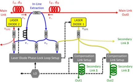
Fig. 1 shows the principle of the multiple dissemination to distant users from a main link, which was first proposed in [15] for radio-frequencies and in [13, 14] for optical frequencies. For clarity, we will first consider the distribution of an ultrastable signal to two users Out0 and Out1. A noise-compensated optical link is established to user Out0, using the well-known technique of the round-trip noise compensation [1, 2]. Corrections are implemented using an acousto-optic modulator (AOM) at the link input. Instead of establishing a second optical link to user Out1, part of the main link is used to disseminate the signal to an intermediate point, called extraction point, where a coupler is inserted to extract both the forward and backward signals propagating in the main link, of frequency ν+ and ν- respectively [13-16]. A narrow bandwidth laser diode is offset phase-locked to the forward extracted signal and feeds a secondary optical link to Out1 [13]. The secondary link is also noise-compensated, using the same method as for the main link. Other secondary links can be fed by the laser diode which enables us to distribute the ultrastable signal to many users simultaneously. A second laser diode can also be phase-locked to the backward extracted signal and feed other secondary links. In that case, the noise compensation will use acousto-optics modulator of opposite shift compared to the ones used for the links fed by the first laser diode [18].
That scheme includes an extraction stage along the main link, as initially proposed in [16] and demonstrated in [13-15, 18]. Both forward and backward extracted signals exhibits phase fluctuations, because the noise correction at the main link input is overcorrecting the phase noise at this intermediate point. Let consider that the extraction is performed at a distance LA from the input end, with the integrated phase noise φA, and LB from the output end, with the integrated phase noise φB (see Fig. 1). The phase fluctuations on the forward extracted signal are given by the sum of the noise φA and the main link correction signal φC0 = - (φA + φB), which results in a noise -φB. To compensate it, we detect the beat-note of the two extracted signals, which exhibits phase fluctuations 2φB. The latter signal, after division by two, is mixed with the control signal of the laser diode, which phase fluctuations are thus free of the main link phase noise.
This set-up enables us to distribute the ultrastable signal to many remote users simultaneously along a main link. It is compatible with optical amplification on main or secondary link and thus with distribution to sites more than 100-km away. We will see in next
paragraph that its implementation does not require that the local RF oscillator is stable and accurate and it can be fully automatized. It is very flexible, since one additional extraction coupler and/or one additional secondary link can be set up on the main link without changing the overall dissemination architecture. By contrast with the branching architecture proposed in [17], the main link is fully independent of the secondary links. But the noise rejection at the secondary links output depends on the proper functioning of the main link.
Fig. 1: principle of the multi-user distribution; a laser diode is phase-locked onto the ultrastable signal extracted along the main link and feeds secondary links, which noise are compensated; OC: optical coupler, LO: local oscillator.
3. Experimental set–up description.
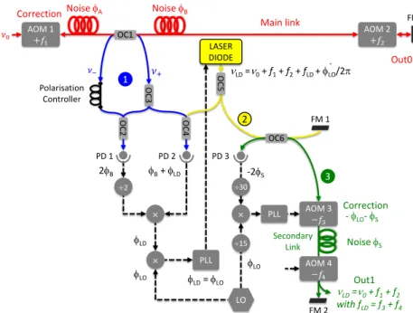
The secondary link set-up was already introduced in [13] and is shown in Fig. 2. It is composed of three parts, the extraction set-up, the optical regeneration with the laser diode, and the noise compensation of the secondary link, respectively labelled 1 to 3 in Fig. 2.
The main link is set-up with the usual round-trip noise compensation method [1, 11], corrections being applied at the link input end through an AOM of frequency f1. It is fed with an ultrastable laser of frequency ν0 which is disseminated from SYRTE through a free-running optical link of 43-km, leading to frequency instabilities in the range of 10-14 [19].
Part of the forward and backward signals propagating on the main link are extracted with a coupler and recombined with a second coupler (part 1 in blue in Fig. 2). This Mach-Zehnder type interferometer gives a beatnote signal on a first photodiode PD1 at frequency 2×f2, where f2 is the frequency of the AOM at the main link output. This signal exhibits the noise 2φB of the upstream part of the main link. A polarisation controller is used to align the polarisation of the two beams, which are perpendicular at the extraction coupler output, since a Faraday mirror is used to reflect the signal at the end of the main link. A 90° Faraday rotator could also be used.
The beatnote signal between the laser diode and the forward extracted signal is detected with a second photodiode PD2 (part 2 in yellow in Fig. 2). A polarisation controller at the laser diode output (not shown in Fig. 2) enables us to optimize its amplitude. This
In-Line Extraction Main Link Out0 Main Link Secondary Link 2 Secondary Link 3 OC , OC OC OC LASER DIODE 2 OC Secondary Link 1 LO OC OC Out1 Out2 Compensation
Link Setup CompensationLink Setup
LASER DIODE 1
Laser Diode Phase-Lock Loop Setup
beatnote signal exhibits both the laser diode phase fluctuations φLD and the main link propagation noise -φB. The latter noise is rejected by mixing this beatnote signal with half the beatnote signal detected on PD1. The resulting signal is used to phase lock the laser diode with an offset frequency fLD given by the local oscillator frequency fLO. The corrections are applied to both the laser temperature and current, with a bandwidth about 100 kHz. The laser diode frequency is thus νLD = ν0 + f1 + f2 + fLO and its phase fluctuations are copying the phase fluctuation φLO of the local oscillator (within the loop bandwidth).
The laser diode is feeding the secondary optical link which noise φS is compensated with again the same round-trip method (part 3 in green in Fig. 2). Two AOMs (denoted AOM3 and AOM4) of negative frequency shifts f3 and f4 are used at the input and output of this secondary link, respectively. The beatnote between the round-trip signal and the input signal, of frequency 2×(f3 + f4), is detected through a Michelson-type interferometer. It exhibits the phase noise -2φS (the minus sign arises from the negative frequency shifts). After division by 30, it is mixed with the signal of the local oscillator, itself divided by 15, to generate corrections applied through AOM3, with a frequency f3 = fLO - f4 and a phase φC1 = - (φS + φLO). Thus the secondary link output frequency is copying the ultra-stable frequency at the main link output ν0 + f1 + f2 without any added phase noise.
Although using a local RF oscillator for the phase-lock loops and AOM drivers, this set-up is insensitive to its frequency fluctuations. We have indeed engineered the set-up so that the RF oscillator instabilities and bias added with the laser diode phase-lock loop are exactly compensated by the secondary link phase corrections. This passive noise compensation is similar to that implemented in the laser stations we have developed for cascaded optical links [12].
Furthermore we designed this set-up to minimize the noise resulting from uncompensated fibre paths [13]. The fibre lengths are minimised and all the passive optical set-up (including the couplers and interferometers) is very compact and installed in an aluminium box which is actively temperature-stabilised at 30° and surrounded with insulating foam. Moreover we carefully adjusted the fibre lengths in order that the temperature sensitivity of the set-up is further reduced. We chose the fibre lengths of both arms between the couplers OC1 and OC2 to be identical (see Fig. 2). In the case of a homogeneous temperature, the phase variation due to any temperature change will thus cancel between the two arms. We also set the fibre length between the laser diode and the optical coupler OC4 to be the sum of the fibre lengths between OC1 and OC4 and between the laser diode output and the Faraday mirror FM1 after OC6. That way, we add to the laser diode phase the opposite of the uncompensated fibre phase variation between the laser output and the Faraday mirror FM1 and the resulting total phase variation cancels.
Fig. 2: Set-up for a secondary link with noise compensation; OC: optical coupler, AOM: acousto-optic modulator, PLL: phase-lock loop, FM: Faraday mirror, PD: photodiode, LO: local oscillator. For simplicity, only the phases have been indicated for the PLLs.
4. Results and discussion.
We implement the multi-user distribution scheme of Fig. 2 at the mid-point of an optical link of 50-km fibre spools. The secondary link is 50-km long. We use an interferometric set-up to detect simultaneously the beatnotes between the input end of the link and the output ends of the main and secondary links, respectively labelled Out0 and Out1 in Fig. 2. These beatnotes enable us to characterize the performance of the frequency transfer at the main and secondary links output ends, the latter being denoted by extraction output below.
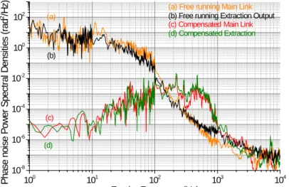
The phase noise Power Spectral Densities (PSD) of these two signals are plot in Fig. 3 (red curve (c) and green curve (d) respectively). The phase noise PSD of the free-running main link (orange curve (a)) and extraction output (black curve (b)) are also shown. By contrast to the other curves, they were measured with a frequency voltage converter which limits the measurement sensitivity after 1 kHz. Both curves are very similar, and typical of optical fiber links, with a noise around 10 rad2/Hz at 1 Hz and 10-6 rad2/Hz at 1 kHz. Both compensated noise are also very similar with a phase noise PSD below 10-5 rad2/Hz between 1 and 50 Hz. The noise is corrected up to around 150 Hz, with a correction overshoot of a few hundreds of Hz compatible with the theoretical bandwidth of 1 kHz given by 1/4τ with τ the propagation delay [2]. Note that this limit is the same for both links but, in case the lengths are different, the bandwidth of the extraction is limited by the longer delay [13]. We checked that the noise floors of both outputs are below these PSDs. The noise rejection of around 106 at 1 Hz is also compatible with the theoretical limit given by 1
3(2𝜋𝜋𝜋𝜋𝜋𝜋)2 which is 8×10 7
for a 50-km link [2]. This shows that the noise rejection is optimized.
÷2 OC 4 OC 3 OC6 × × Polarisation Controller FM 1 FM 2 OC 2 FM PD 1 PD 2 PD 3 1 2 3 OC1 OC 5 LASER DIODE 2φB φB+ φLD φLD φLO φ LD= φLO φLO νLD=ν0+ f1+ f2 with fLD= f3+ f4
Correction Noise φA Noise φB
νLD=ν0+ f1+ f2+ fLD+ φLO/2π . Correction - φLO- φS Secondary Link Main link Noise φS -2φS Out0 Out1 ÷15 AOM 3 PLL PLL AOM 4 × AOM 2 AOM 1 LO ÷30 5
Fig. 3: Phase noise power spectral density of (a) the free-running main link (orange line), (b) the free-running extraction output (black line), (c) the compensated main link (red line) and (d) the compensated extraction output (green line).
To evaluate the end-to-end stabilities, the beat-notes at frequency f1 + f2 = 75 MHz are tracked with a 100 kHz bandwidth and after frequency division by 2 they are recorded simultaneously with a dead-time free counter (Kramer+Klische FXE) with a gate time of 1 s and Λ-type operation, in order to average out the noise in a narrow bandwidth [20, 21]. We then use the modified Allan deviation to characterise the stability of the extraction set-up.
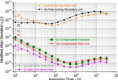
Fig. 4 displays the experimental stability of the free-running main link (orange circles (a)) and secondary link (black down-triangles (b)). Their noise slightly differs because the main link fibre is wound onto a spool and thus experiences some constraints, whereas the secondary link fibre is wound freely (without any central spool). The extraction output stability (green squares (c)) is 1×10-17 at 1 s averaging time, decreases and reaches a floor of about 4×10-20 after 104 s. It is at the state of the art for fibre frequency transfer on such distances and nearly copies the main link output stability. Note that the noise correction is very robust and that the set-up was operated during 2.5 day without any cycle-slip. At short-term, the stability is slightly above the main link output stability (red up-triangles (d)) which is 6×10-18 at 1 s averaging time. The extraction output indeed exhibits both the contribution of the signal extracted from the main link (after compensation of φB) and the residual noise of the secondary link, the latter limiting the noise rejection at short term. In Fig. 4 is also shown the noise floors for both the main link (pink diamonds (f)) and the extraction output (grey stars (e)), which limit the long-term stability. The latter is mainly attributed to thermal noise on uncompensated fibre paths, due to imperfect length adjustment and thermal stabilisation in the extraction optical set-up, or in the interferometric measurement set-up.
100 101 102 103 104 10-8 10-6 10-4 10-2 100 102 (c) (d) (b) (a)
(c) CompensatedMain Link
(d) Compensated Extraction
(b) Free running Extraction Output
P h a se n oi se P o w e r S p e ct ra l D e n si tie s (r a d 2 /Hz ) Fourier Frequency (Hz)
(a) Free running Main Link
Fig. 4: End-to-end fractional frequency instability, calculated from Λ-type data with the Modified Allan deviation, of (a) the km free-running main link (orange circles), (b) the 50-km secondary link (black down-triangles) (c) the compensated extraction output (green squares), (d) the compensated main link output (red up-triangles), (e) the extraction noise floor (grey stars) and (f) the main link noise floor (pink diamonds).
Fig. 5: End-to-end fractional frequency instability, calculated from Λ-type data with the overlapping Allan deviation, of (a) the compensated extraction output (green squares) and (b) the compensated main link output (red up-triangles).
Finally, the accuracy of the frequency transfer was evaluated by calculating the mean value of the end-to-end beat note frequency offset. Following [4, 22], we estimate its statistical fractional uncertainty as the long-term overlapping Allan deviation at 20000 or 30000 s of the data set. We obtained for the main link a mean frequency offset of -8.2×10⁻²¹ with a statistical uncertainty of 4×10-20. For the extraction output, the mean frequency offset is -2.4×10⁻²¹ with a statistical uncertainty of 4×10-20. These figures show that the frequency transfer shows no bias to the expected value.
With this link performance, the ultra-stable laser is thus transferred through the secondary and main links without degradation. Even a record ultrastable laser exhibiting a 10-16 stability at 1 s averaging time [23] would be faithfully transferred for integration time above 1 s.
100 101 102 103 104 105 10-21 10-20 10-19 10-18 10-17 10-16 10-15 10-14 10-13
(e) Extraction Noise Floor (f) Main Link Noise Floor
(a) Free-running Main Link (b) Free-running Secondary Link
(c) CompensatedExtraction
(d) CompensatedMain Link
(f) M od ifi e d A llan D e vi a tio n σy (τ ) Averaging Time τ (s) (e) (d) (c) (b) (a) 100 101 102 103 104 105 10-20 10-19 10-18 10-17
(a) Extraction Compensated
(b) Main Link Compensated
O ve rl a pp in g A lla n D e vi a tion σy (τ ) Averaging Time τ (s) (b) (a) 7
5. Testing the noise rejection on the main link
We have shown that our extraction set-up enables us to transfer the ultrastable signal to several users simultaneously, using secondary links to reach the more distant ones. We are now discussing an alternative application of an extraction set-up, which consists in testing the proper functioning of the noise rejection on the main link.
As pointed out by several authors, one can test the performance of an optical link by analysing the end-to-end stability, which requires that the two ends are at the same place. Thus optical links are usually implemented with two parallel fibres or with a loop fibre. But it is not always possible to get such configuration, which requires the doubling of the fibre lengths to the distant lab, and thus increases the equipment and maintenance costs. Calonico and co-workers implemented a double round-trip on a single fibre in order to characterize the link performance [24]. This alternative method is very beneficial for long-haul link network development but could be difficult to implement when the fibre attenuation and parasitic noise are large. Here we propose to use an extraction set-up at the link input to test the good functioning of the noise rejection on the main link. As demonstrated in [13], the extraction end phase noise PSD without any secondary link is lower or equal to the main link output phase noise PSD. When the extraction occurs at the link input, the phase correction at the extraction output is exactly opposite to the roundtrip fibre phase noise and thus to the correction at the link input. Therefore, following our simple model detailed in [13], the extracted signal copies exactly the input signal and no fibre phase fluctuation is added to the signal. Thus, by analysing the extracted signal, we can infer that the noise correction signal applied at the link input is properly compensating the main link noise. For that purpose, one has to carefully implement the stability measurement set-up: the lengths of the fibres used to detect the beatnote between the input end of the link and the extraction end should be carefully balanced and thermalized in order that the noise arising from these uncommon fibre paths is negligible.
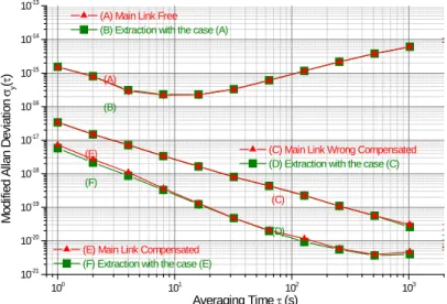
Fig. 6: End-to-end fractional frequency instability, calculated from Λ-type data with the Modified Allan deviation, of the main link (red up-triangles) and the extraction output (green squares) for three pairs of data: (a) and (b) free-running main link, (c) and (d) poorly compensated main link, and (e) and (f) compensated main link. Error bars are too small to show on Figure.
100 101 102 103 10-21 10-20 10-19 10-18 10-17 10-16 10-15 10-14 10-13
(E) Main Link Compensated
(F) Extraction with the case (E)
(A) Main Link Free
(B) Extraction with the case (A)
(C) Main Link Wrong Compensated
(D) Extraction with the case (C) (F) M odi fied A llan D ev iat ion σy (τ ) Averaging Time τ (s) (E) (D) (C) (B) (A) 8
In order to validate this method, we implemented our extraction set-up at the main link input, and we replaced the secondary link by an equivalent attenuator. Then we compare the main link output stability with the extraction stability for the following three cases: the free-running main link, a partial noise compensation of the main link, with a poor adjustment of the loop gains, and an optimized noise compensation of the main link. The three pairs of stabilities are shown in Fig. 6, with red-up triangles for the main link and green squares for the extraction output. In each case, the extraction stability is almost copying the main link output stability. Note that for the compensated main link, the extraction stability is 5.9×10⁻¹⁸ at 1-s averaging time when the main link output stability is 7.5×10⁻¹⁸. The ratio of the square of these stabilities gives an estimate of the F-factor we introduced in [13]. It is 0.6, when the theoretically expected value is 0. This can be explained by the fact that the stability at 1 s is limited by the noise floor (as can be seen on Fig. 4) which is expected to be mainly due to the electronic detection set-up.
The stabilities displayed in Fig. 6 show that the extraction stability is a very good measurement of the main link stability and enables us to check the right functioning of the noise rejection. Such set-up can be used to test the proper operation of a single-fibre link. It is very beneficial when implementing the first spans of a cascaded link without having set-up the next spans. It is also very useful when implementing an uncompensated link to a distant user, in order to evaluate these user link instabilities. Note that, for these applications, we don’t need to phase-lock a laser diode to the extracted signal; the simpler extraction set-up we have demonstrated in [13] is more than enough.
6. Conclusion
We have demonstrated the distribution of an ultrastable frequency to two distant users using a single link input. We use a new type of branching network topology with a secondary link departing from any position along a main link. This architecture enables us to establish an ultrastable frequency distribution to multiple users, for example in a dense metropolitan area. It is a very interesting alternative to point-to-point distribution, which requires one optical link per user and thus a higher cost of fibre equipment and maintenance. We have shown that the stability at the secondary link output is nearly copying that at the main link output, with an Allan deviation of 10-17 at 1-s averaging time. This set-up is very robust and can be operated without any stable RF oscillator at the extraction point, since the secondary link output stability is independent of this local oscillator’s instabilities. It can be implemented on an active telecommunication network with simultaneous data traffic, provided that we set-up optical add-drop multiplexers to insert or extract the ultrastable signal from the data traffic [11].
This work is a major step of the French project named REFIMEVE+ [25]. REFIMEVE+ is developing a wide national infrastructure where a reference optical signal generated at SYRTE will be distributed to about twenty academic and institutional users using the National Academic network RENATER. Such an extraction set-up will be mainly implemented for metropolitan area distribution, as for example in the Paris area. It is also a key-element of the current effort to establish continental ultra-stable fibre network. Multi-users dissemination opens the way to a wide distribution of an ultra-stable frequency
reference, enabling applications beyond metrology [6-10] and we expect that it will stimulate the development of new high-sensitivity experiments in a broad range of applications.
Acknowledgments
We acknowledge Christian Chardonnet and Saïda Guellati-Khelifa for stimulating this work and Giorgio Santarelli for fruitful discussions. We also acknowledge A. Kaladjian and F. Wiotte from LPL for technical support. We acknowledge funding support from the Agence Nationale de la Recherche the Agence Nationale de la Recherche (ANR blanc LIOM 2011-BS04-009-01, Labex First-TF ANR 10 LABX 48 01) and IFRAF-Conseil Régional Ile-de-France.
References.
1. Ma, L.S., et al., Delivering the same optical frequency at two places: accurate
cancellation of phase noise introduced by an optical fiber or other time-varying path. Optics Letters, 1994. 19(21): p. 1777-1779.
2. Newbury, N.R., P.A. Williams, and W.C. Swann, Coherent transfer of an optical
carrier over 251 km. Optics Letters, 2007. 32(21): p. 3056.
3. Droste, S., et al., Optical-Frequency Transfer over a Single-Span 1840 km Fiber Link. Physical Review Letters, 2013. 111(11): p. 110801.
4. Raupach, S.M.F., A. Koczwara, and G. Grosche, Brillouin amplification supports 1 x
10-20 accuracy in optical frequency transfer over 1400 km of underground fibre. Physical Review A, 2015. 92(2): p. 021801(R).
5. C. Lisdat, G.G., N. Quintin, C. Shi, S.M.F. Raupach, C. Grebing, D. Nicolodi, F.
Stefani, A. Al-Masoudi, S. Dörscher, S. Häfner, J.-L. Robyr, N. Chiodo, S. Bilicki, E. Bookjans, A. Koczwara, S. Koke, A. Kuhl, F. Wiotte, F. Meynadier, E. Camisard, M. Abgrall, M. Lours, T. Legero, H. Schnatz, U. Sterr, H. Denker, C. Chardonnet, Y. Le Coq, G. Santarelli, A. Amy-Klein, R. Le Targat, J. Lodewyck, O. Lopez, P.-E. Pottie, A new era of international clock measurements. arXiv:1511.07735, 2015.
6. Matveev, A., et al., Precision measurement of the Hydrogen 1S-2S frequency via a
920-km fiber link. Physical Review Letters, 2013. 110(23): p. 230801.
7. C. Clivati, et al., Measuring absolute frequencies beyond the GPS limit via long-haul optical frequency dissemination. arXiv:1511.08485 [physics.optics], 2015.
8. Chanteau, B., et al., Mid-infrared laser phase-locking to a remote near-infrared
frequency reference for high-precision molecular spectroscopy. New Journal of Physics, 2013. 15(7): p. 073003.
9. Argence, B., et al., Quantum cascade laser frequency stabilization at the sub-Hz level. Nat Photon, 2015. 9(7): p. 456-460.
10. C. Clivati, R.A., C. Bortolotti, G. A. Costanzo, M. Frittelli, F. Levi, and F.P. A. Mura, M. Roma, M. E. Zucco and D. Calonico, The Optical Fiber Link LIFT for Radioastronomy. Proceedings of 2015 Joint Conference of the IEEE International Frequency Control Symposium & European Frequency and Time Forum, 2015: p. 769-772.
11. Lopez, O., et al., Cascaded multiplexed optical link on a telecommunication network for frequency dissemination. Optics Express, 2010. 18(16): p. 16849.
12. Chiodo, N., et al., Cascaded optical fiber link using the internet network for remote clocks comparison. Optics Express, 2015. 23(26): p. 33927-33937.
13. Bercy, A., et al., In-line extraction of an ultrastable frequency signal over an optical fiber link. Journal of the Optical Society of America B, 2014. 31(4): p. 678-685.
14. Grosche, G., Eavesdropping time and frequency: phase noise cancellation along a
time-varying path, such as an optical fiber. Optics letters, 2014. 39(9): p. 2545-2548. 15. Krehlik, P., et al., Multipoint dissemination of RF frequency in fiber optic link with
stabilized propagation delay. Ultrasonics, Ferroelectrics, and Frequency Control, IEEE Transactions on, 2013. 60(9): p. 1804-1810.
16. Grosche, G., Method for making available a reference frequency. German patent
application DE 10.2008.062.139, 2010.
17. Schediwy, S.W., et al., High-precision optical-frequency dissemination on branching optical-fiber networks. Optics letters, 2013. 38(15): p. 2893-2896.
18. Bai, Y., et al., Fiber-based multiple-access optical frequency dissemination. Optics letters, 2013. 38(17): p. 3333-3335.
19. Jiang, H., et al., Long-distance frequency transfer over an urban fiber link using
optical phase stabilization. J. Opt. Soc. Am. B, 2008. 25(12): p. 2029-2035.
20. Rubiola, E., On the measurement of frequency and of its sample variance with
high-resolution counters. Review of scientific instruments, 2005. 76: p. 054703.
21. Dawkins, S.T., J.J. McFerran, and A.N. Luiten, Considerations on the Measurement of the Stability of Oscillators with Frequency Counters. Ieee transactions on ultrasonics, ferroelectrics, and frequency control, 2007. 54: p. 918-925.
22. Lopez, O., et al., Frequency and time transfer for metrology and beyond using
telecommunication network fibres. Comptes Rendus Physique, 2015. 16: p. 531-539. 23. Kessler, T., et al., A sub-40-mHz-linewidth laser based on a silicon single-crystal
optical cavity. Nature Photonics, 2012. 6(10): p. 687-692.
24. Calonico, D., et al., High-accuracy coherent optical frequency transfer over a doubled 642-km fiber link. Applied Physics B, 2014. 117(3): p. 979-986.
25. Refimeve+, project www.refimeve.fr/.