HAL Id: tel-02366888
https://hal-univ-pau.archives-ouvertes.fr/tel-02366888
Submitted on 16 Nov 2019HAL is a multi-disciplinary open access archive for the deposit and dissemination of sci-entific research documents, whether they are pub-lished or not. The documents may come from teaching and research institutions in France or abroad, or from public or private research centers.
L’archive ouverte pluridisciplinaire HAL, est destinée au dépôt et à la diffusion de documents scientifiques de niveau recherche, publiés ou non, émanant des établissements d’enseignement et de recherche français ou étrangers, des laboratoires publics ou privés.
Hygro-mechanical characterisation of hypercompacted
earth for building construction
Agostino Walter Bruno, Domenico Gallipoli, Agostino Bruno
To cite this version:
Agostino Walter Bruno, Domenico Gallipoli, Agostino Bruno. Hygro-mechanical characterisation of hypercompacted earth for building construction. Construction durable. Université de Pau et des Pays de l’Adour - Laboratoire SIAME, 2016. English. �tel-02366888�
Hygro-mechanical characterisation of
hypercompacted earth for building
construction
By
Agostino Walter Bruno
A thesis submitted in fulfilment of the requirements for the
degree of Doctor of Philosophy in Civil Engineering
Université de Pau et des Pays de l’Adour
École Doctorale des Sciences Exactes et de leur applications
Public defence on 28th October 2016
Members of the Thesis Jury:
Pr. Jean-Emmanuel AUBERT President
Pr. Jean-Claude MOREL Reviewer
Pr. Charles AUGARDE Reviewer
Pr. Monika WOLOSZYN Invited member
Pr. Antonin FABBRI Invited member
Dr. Christophe CANTAU Invited member
Pr. Domenico GALLIPOLI Supervisor
MCF Céline PERLOT Supervisor
The string has not been cut I am not far You see, everything is fine Wipe your tears and cry no more If you love me: your smile is my peace St. Augustine
T
ABLE OF
C
ONTENTS
TABLE OF CONTENTS ... I LIST OF FIGURES ... IV LIST OF TABLES ... IX AKNOWLEDGMENTS ... XI ABSTRACT ... XII RESUMÉ ... XIV 1 INTRODUCTION ... 1 1.1RAW EARTH MATERIALS ... 1 1.2HISTORICAL OVERVIEW ... 21.3RAW EARTH CONSTRUCTION TECHNIQUES ... 5
1.3.1 Ancient raw earth construction ... 5
1.3.2 Modern raw earth construction ... 6
1.4ADVANTAGES AND LIMITATIONS OF RAW EARTH MATERIALS ... 8
1.4.1 Reasons behind current renaissance of earthen constructions ... 8
1.4.2 Some limitations of raw earth construction ... 12
1.5RESEARCH OBJECTIVES ... 16
1.6THESIS LAYOUT ... 17
2 RAW EARTH: REVIEW OF MAIN ENGINEERING PROPERTIES ... 18
2.1PHYSICAL PROPERTIES OF RAW EARTH MATERIALS ... 18
2.1.1 Grain size distribution ... 18
2.1.2 Clay mineralogy ... 23
2.1.3 Plasticity ... 24
2.1.4 Microstructural properties ... 25
2.2MECHANICAL BEHAVIOUR ... 28
2.2.1 Serviceability state: Young modulus and Poisson ratio ... 29
2.2.2 Ultimate state: compressive strength ... 33
2.2.3 Effect of dry density on compressive strength ... 35
2.2.4 Effect of ambient humidity and temperature on compressive strength ... 38
2.3MOISTURE BUFFERING CAPACITY ... 42
3 MATERIAL AND METHODS... 54
3.1MATERIAL CHARACTERISATION ... 54
3.1.1 Grain size distribution ... 54
3.1.2 Plasticity and specific gravity of soil solids ... 55
3.2COMPACTION PROCEDURES ... 57
3.2.1 Hypercompaction method: cylindrical samples ... 57
3.2.2 Proctor standard ... 63
3.2.3 Compaction curves ... 64
3.2.4 Equalisation ... 67
3.3HYPERCOMPACTION METHOD: BRICK SCALE ... 68
3.3.1 Press and compaction mould ... 68
3.3.2 Compaction procedure ... 70
3.4STABILISATION METHODS ... 74
3.5FINAL REMARKS ... 79
4 MICROSTRUCTURAL ANALYSIS ... 81
4.1MERCURY INTRUSION POROSIMETRY TESTS ... 81
4.1.1 Sample preparation and testing procedure ... 82
4.1.2 Processing of raw data ... 84
4.2RESULTS OF MERCURY INTRUSION POROSIMETRY TESTS ... 87
4.2.1 Effect of compaction effort ... 87
4.2.2 Analysis of sample homogeneity ... 89
4.2.3 Effect of compaction water content ... 91
4.3NITROGEN ADSORPTION ... 94
4.3.1 Sample preparation and testing procedure ... 94
4.3.2 Effect of compaction effort ... 95
4.4FINAL REMARKS ... 95
5 MECHANICAL BEHAVIOUR ... 97
5.1EFFECT OF DENSITY OF UNSTABILISED EARTH ... 97
5.1.1 Young modulus ... 98
5.1.2 Poisson ratio ... 100
5.1.3 Shear modulus ... 101
5.1.4 Compressive strength ... 102
5.2EFFECT OF CONSOLIDATION TIME OF UNSTABILISED EARTH ... 105
5.3EFFECT OF RELATIVE HUMIDITY ... 108
5.3.2 Young modulus and compressive strength of stabilised earth ... 112
5.4COMPRESSIVE STRENGTH OF COMPRESSED EARTH BRICKS ... 115
5.4.1 Effect of aspect ratio ... 116
5.4.2 Effect of Teflon capping ... 118
5.4.3 Effect of mortar joint ... 120
5.4.4 Effect of anisotropy ... 121
5.5FINAL REMARKS ... 123
6 HYGROSCOPIC BEHAVIOUR ... 126
6.1TESTING PROCEDURE ... 126
6.2MOISTURE BUFFERING CAPACITY OF UNSTABILISED SAMPLES ... 128
6.3MOISTURE BUFFERING CAPACITY OF STABILISED SAMPLES ... 132
6.4COMPARISON BETWEEN BRICKS AND CYLINDRICAL SAMPLES... 136
6.5FINAL REMARKS ... 138 7 DURABILITY PROPERTIES ... 140 7.1SUCTION TEST ... 141 7.2CONTACT TEST ... 143 7.3BRICKS CLASSIFICATION... 145 7.4FINAL REMARKS ... 146 8 CONCLUSIONS ... 148
8.1MATERIAL AND METHODS ... 148
8.2MICROSTRUCTURAL ANALYSIS ... 150
8.3MECHANICAL BEHAVIOUR ... 151
8.4HYGROSCOPIC BEHAVIOUR ... 154
8.5DURABILITY PROPERTIES ... 155
8.6RECOMMENDATIONS FOR FUTURE WORKS ... 155
REFERENCES ... 157
L
IST OF
F
IGURES
1 INTRODUCTION ... 1
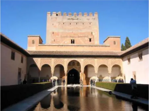
Figure 1.1. Example of historical rammed earth building: the
Alhambra Palace in Granada, Spain, built in the 10th century ... 3
Figure 1.2. Example of modern rammed earth building: the Haus Rath
in Weilburg an der Lahn, Germany, built in 1828 ... 3
Figure 1.3. Ancient raw earth construction ... 6 Figure 1.4. Modern raw earth construction ... 8 Figure 1.5. Energy consumption by sectors. Source: European
commission, US Department of Energy, Japanese Resource and
Energy Agency (OECD, 2003) ... 10
2 RAW EARTH: REVIEW OF MAIN ENGINEERING PROPERTIES... 18
Figure 2.1. Grain size distribution: upper and lower limits for
compressed earth blocks according to AFNOR (2001), CRATerre-
EAG (1998) and MOPT (1992) ... 19
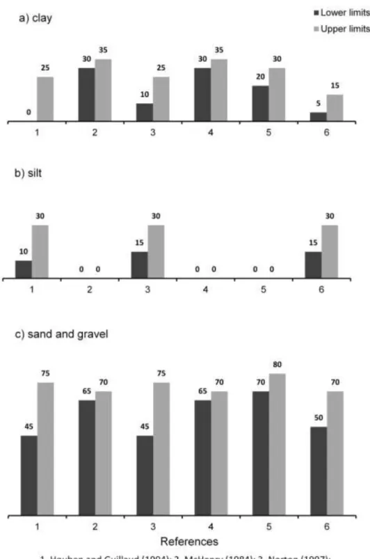
Figure 2.2. Recommended lower and upper proportions of a) clay, b)
silt and c) sand and gravel in earthen materials according to various
authors ... 20
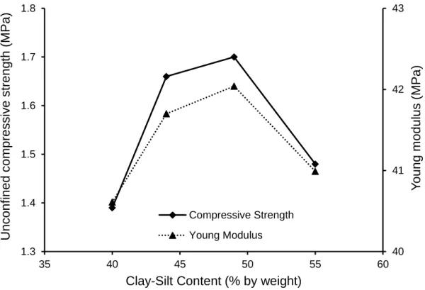
Figure 2.3. Stiffness and strength of earth mixes with different clay-silt
fractions (after Wu et al., 2002) ... 21
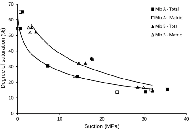
Figure 2.4. Drying curves for coarse earth Mix A and fine earth Mix B
(after Jaquin et al., 2008) ... 22
Figure 2.5. Drying curves for coarse earth Mix 7:1:2 and fine earth
Mix 5:1:4 (after Beckett and Augarde, 2012) ... 23
Figure 2.6. Plasticity chart: indications for CEB given by AFNOR
(2001), CRATerre- EAG (1998) and Houben and Guillaud (1994) ... 25
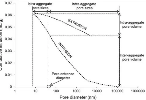
Figure 2.7. Inter- and Intra- aggregate pore volume determined by
MIP intrusion and extrusion (test taken from experimental campaign
presented in Chapter 4) ... 26
Figure 2.8. Pore size distribution of untreated and lime treated silty
soil (dashed lines: WMC, solid lines: OMC). (Cuisinier et al., 2011) ... 28
Figure 2.9. Stress-strain curve for Adobe and BAP (Kouakou and
Figure 2.10. Initial tangent modulus and equivalent modulus of BAP
(after Kouakou and Morel, 2009) ... 30
Figure 2.11. Variation of Young modulus with water content (after Bui
et al., 2014) ... 32
Figure 2.12. Variation of Poisson ratio with water content (after Bui
et al., 2014) ... 32
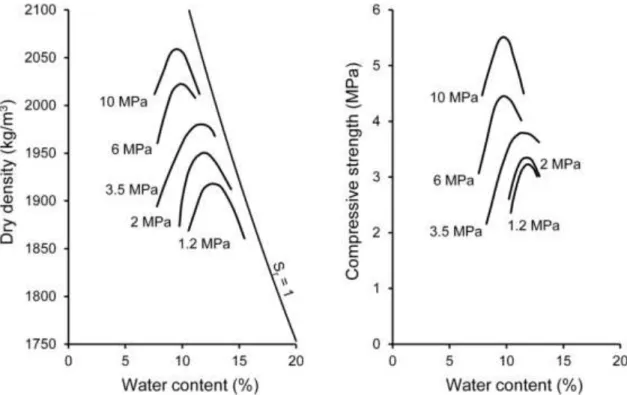
Figure 2.13. Compaction curves and variation of compressive strength
with water content and compaction pressure (after Olivier and
Mesbah, 1986) ... 37
Figure 2.14. Variation of compressive strength with dry density (after
Morel et al., 2007) ... 37
Figure 2.15. Variation of compressive strength with dry density (after
Kouakou and Morel, 2009) ... 38
Figure 2.16. Variation of compressive strength with water content
(after Bui et al., 2014) ... 39
Figure 2.17. Variation of compressive strength with air humidity and
suction (after Dierks and Ziegert, 2014) ... 40
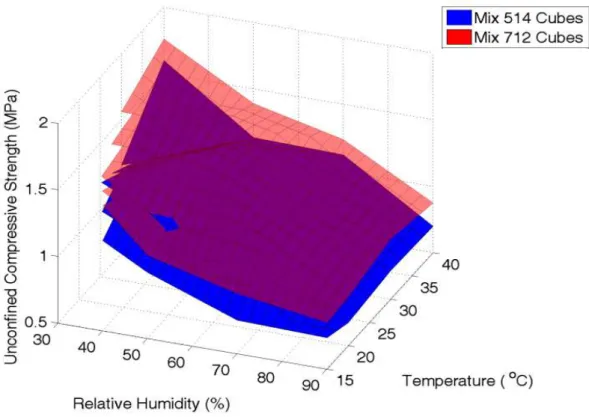
Figure 2.18. Variation of compressive strength with relative humidity
and temperature (after Beckett and Augarde, 2012) ... 41
Figure 2.19. Variation of compressive strength with suction:
comparison between Bui et al. (2014), Jaquin et al. (2009) and Beckett
and Augarde (2012) ... 42
Figure 2.20. MBV measured by DTU, NBI and VTT measured on
different construction materials (Rode et al., 2005) ... 44
Figure 2.21. MBV measured on unstabilised and stabilised earthen
samples: comparison between different test procedures (after
McGregor et al., 2014) ... 46
Figure 2.22. Moisture sorption of various building materials (after
Eckermann and Ziegert, unpublished work 2006) ... 47
Figure 2.23. Molecular structures of polysiloxane (Kebao and Kagi,
2012) ... 50
Figure 2.24. Water absorption of rammed earth substrate (after Kebao
and Kagi, 2012) ... 51
Figure 2.25. Water vapour transmission of rammed earth substrate
3 MATERIAL AND METHODS... 54
Figure 3.1. Grain size distribution of the tested soil ... 55
Figure 3.2. Plasticity properties of the tested soil in relation to the admissible region for compressed earth bricks ... 56
Figure 3.3. Zwick/Roell Amsler HB250 press and compaction mould ... 59
Figure 3.4. Compaction system: a) vertical cross section of experimental set-up during double compaction and b) mould and pistons ... 61
Figure 3.5. Typical vertical displacement versus square root of time during consolidation ... 62
Figure 3.6. Compaction curves of Proctor samples and cored samples ... 64
Figure 3.7. Compaction curves at 25, 50 and 100 MPa together with standard Proctor ... 67
Figure 3.8. Change in dry density and water content during equalisation ... 68
Figure 3.9. 3R 3000 TC/TH compression press ... 69
Figure 3.10. Compaction mould: a) disassembled b) assembled ... 71
Figure 3.11. Double compaction of earth brick ... 72
Figure 3.12. Brick demoulding phase ... 73
Figure 3.13. Results from the first campaign of immersion tests ... 76
Figure 3.14. Results from the second campaign of immersion tests ... 78
4 MICROSTRUCTURAL ANALYSIS ... 81
Figure 4.1. Micromeritics AutoPore IV Mercury Porosimeter ... 82
Figure 4.2. Freeze-drier Crios (Cryotec) ... 83
Figure 4.3. Zoomed view at the transition between low and high pressure stages: correction of raw data ... 85
Figure 4.4. Typical result of raw data processing ... 86
Figure 4.5. Comparison between Proctor standard and hypercompaction: intruded and extruded cumulative volumes (a) and pore size distribution (b) ... 88
Figure 4.6. Comparison top, middle and bottom height: cumulative volume (a) and pore size distribution (b) ... 90
Figure 4.7. Water content and dry density of samples compacted according to Proctor standard and at 100 MPa ... 92
Figure 4.8. Effects of compaction water content. Comparison Proctor
standard and 100 MPa: cumulative volume (a) and pore size
distribution (b) ... 93
Figure 4.9. Micromeritics TriStar II Surface Area and Porosity equipment ... 94
Figure 4.10. Nitrogen adsorption tests. Comparison of pore size distributions between specimens compacted at 25 MPa, 50 MPa and 100 MPa ... 95
5 MECHANICAL BEHAVIOUR ... 97
Figure 5.1. Testing set-up for measuring axial and radial displacements ... 98
Figure 5.2. Typical cyclic test for measuring stiffness properties (sample S09-CS100-W6.2 – see Table 3.3) ... 99
Figure 5.3. Variation of Young modulus with dry density ... 100
Figure 5.4. Variation of Poisson ratio with dry density ... 101
Figure 5.5. Variation of shear modulus with dry density ... 102
Figure 5.6. Typical compressive failure mechanism (sample S10-CS50-W5.2 – see Table 3.3) ... 104
Figure 5.7. Stress-strain curves: tests performed on similar samples but at different displacement rates ... 104
Figure 5.8. Variation of compressive strength with dry density... 105
Figure 5.9. Relationship between dry density and consolidation time ... 106
Figure 5.10. Variation of Young modulus with consolidation time ... 107
Figure 5.11. Variation of compressive strength with consolidation time ... 107
Figure 5.12. Variation of Young modulus with total suction: unstabilised samples... 111
Figure 5.13. Variation of compressive strength with total suction: unstabilised samples... 111
Figure 5.14. Variation of Young modulus with total suction: unstabilised and stabilised samples compacted at 100 MPa ... 114
Figure 5.15. Variation of compressive strength with total suction: unstabilised and stabilised samples compacted at 100 MPa ... 114
Figure 5.16. Loading directions 1, 2 and 3 perpendicular to the largest, intermediate and smallest brick surfaces ... 117
Figure 5.17. Variation of compressive strength with aspect ratio ... 117
Figure 5.18. Failure mechanisms corresponding to loading directions 2 and 3 ... 118
Figure 5.19. Compressive strength of bricks with or without Teflon capping ... 119
Figure 5.20. Compressive strength of superimposed half-bricks with or without cement mortar ... 121
Figure 5.21. Compressive strength of cubic specimens: effect of anisotropy ... 122
6 HYGROSCOPIC BEHAVIOUR ... 126
Figure 6.1. Climatic chamber CLIMATS Type EX2221-HA ... 127
Figure 6.2. Moisture adsorption of unstabilised samples compacted at 25, 50 and 100 MPa ... 129
Figure 6.3. MBV uptake and MBV release of samples compacted at 25, 50 and 100 MPa ... 130
Figure 6.4. MBV of unstabilised compressed earth measured in the present work compared to results of Rode et al. (2005) ... 131
Figure 6.5. MBV of unstabilised compressed earth measured in the present work compared to results of McGregor et al. (2014) ... 132
Figure 6.6. Last stable cycle of unstabilised and stabilised samples ... 134
Figure 6.7. MBV uptake and MBV release of stabilised samples ... 135
Figure 6.8. MBV of unstabilised and stabilised samples ... 135
Figure 6.9. View of the three earth bricks before testing: unsealed surface (200x100 mm2) and two of the five sealed surfaces (200x50 mm2 and 200x100 mm2) ... 137
Figure 6.10. Last stable cycle of compressed earth bricks and cylindrical samples ... 138
7 DURABILITY PROPERTIES... 140
Figure 7.1. Set-up of suction test ... 142
Figure 7.2. Results from suction tests on unstabilised and stabilised compressed earth bricks ... 143
Figure 7.3. Set-up of contact test ... 144
Figure 7.4. Results from contact tests on unstabilised and stabilised compressed earth bricks ... 144
L
IST OF
T
ABLES
2 RAW EARTH: REVIEW OF MAIN ENGINEERING PROPERTIES ... 18
Table 2.1. Grain size distribution of tested materials (after Bui et al., 2014) ... 31
Table 2.2. Aspect ratio correction factors ... 34
Table 2.3. Ranges for MBV categories ... 45
Table 2.4 Testing conditions: humidity control environment (McGregor et al., 2014) ... 45
Table 2.5. Classes of compressed earth bricks ... 48
Table 2.6. Compressed earth bricks: results from durability tests ... 49
3 MATERIAL AND METHODS ... 54
Table 3.1. Compressive strength of different materials tested by LMDC (Toulouse) ... 54
Table 3.2. Main material properties ... 57
Table 3.3. Properties of samples after compaction ... 65
Table 3.4. Main properties of all compressed earth bricks after equalisation at T=25 °C ... 73
Table 3.5. Composition of all tested additive solutions (first campaign) ... 75
Table 3.6. Composition of all tested additive solutions (second campaign) ... 77
4 MICROSTRUCTURAL ANALYSIS ... 81
Table 4.1. Inter- and intra-aggregate pore volumes, pore diameter boundary between inter- and intra-aggregate porosity ... 88
5 MECHANICAL BEHAVIOUR ... 97
Table 5.1. Properties of unstabilised samples after equalisation at different RH levels ... 110
Table 5.2. Properties of stabilised/unstabilised samples after equalisation at different RH levels ... 113
7 DURABILITY PROPERTIES... 140
Table 7.1. Classes of compressed earth bricks (DIN 18945, 2013) ... 145 Table 7.2. Classification of earth bricks depending on type of
ACKNOWLEDGEMENTS
I acknowledge the “Conseil regional d’Aquitaine” and the “Agglomération Côte Basque Adour” for supporting this project which was carried out in the laboratory SIAME at the Université de Pau et des Pays de l’Adour.
I would like to express my gratitude to Pr. Domenico Gallipoli, MCF Céline Perlot-Bascoulès and Dr. Joao Mendes for supervising this project and offering me their passionate and enthusiastic support. Their high standard supervision has been precious for my scientific and personal enrichment.
I would like to thank all the members of SIAME and ISA-BTP, specially Pr. Christian La Borderie for the useful discussions about my research.
I would also like to thank Nicolas Salmon, Christophe Cantau and Laurène Felix (Nobatek – INEF4) for the periodic meetings and exchanges throughout this project. My sincere thanks go to my friends and colleagues with whom I shared the past three years.
Very special thanks to my family. I am deeply grateful to my father Agatino and my two sisters Valeria and Elena for all the sacrifices they have made for me. Finally, I could not have completed this work without the emotional support of Federica, who unreservedly encouraged me mainly in the most difficult times.
ABSTRACT
The present work explores the hygro-mechanical behaviour of a raw earth material and investigates different stabilisation techniques to improve the durability of the material against water erosion. An extensive campaign of laboratory tests was performed on both unstabilised and stabilised materials at two different scales: small cylindrical samples and large bricks.
An innovative manufacturing method based on the application of very high compaction pressures (hypercompaction) was proposed. Also, the compaction load was maintained constant for a sufficient period of time to allow soil consolidation. The main objective was to increase material density, thus improving mechanical performance. Samples
compacted with the proposed method exhibited a dry density of about 2320 kg/m3,
which is the highest value registered in the literature for an unstabilised earthen material.
The effect of the compaction pressure on the material fabric was assessed by means of mercury intrusion porosimetry and nitrogen adsorption tests. Results showed that the increase of compaction pressure reduced material porosity with major effects on large inter-aggregate pores. On the contrary, small intra-aggregate pores were not affected by the mechanical compaction.
Mechanical tests were then performed to measure stiffness and strength of both unstabilised and stabilised samples. These tests demonstrated that hypercompaction can largely improve the mechanical response of the material over conventional manufacturing methods. Hypercompacted bricks showed a compressive strength comparable with that of traditional building materials, such as stabilised compressed earth and fired bricks.
The hygroscopic behaviour of both unstabilised and stabilised samples was investigated. The capacity of the samples to absorb/release water vapour was assessed by measuring their moisture buffering value (MBV). Results showed that unstabilised earth has an excellent capacity to buffer ambient humidity. This capacity was significantly reduced by the different stabilisation techniques tested in the present work.
Finally, the durability against water erosion of both unstabilised and stabilised bricks was assessed by performing different tests prescribed by the norm DIN 18945 (2013). Stabilised bricks exhibited a higher resistance against water erosion compared to unstabilised bricks. Still, these materials cannot be adopted for structural applications exposed to natural weathering as indicated by the norm DIN 18945 (2013). Therefore, further investigation is required to identify novel stabilisation methods that can balance the needs of sustainability, durability, moisture buffering and mechanical performance.
KEYWORDS: Raw earth construction, hypercompaction method, compressed earth
bricks, stiffness, compressive strength, moisture buffering capacity, stabilisation techniques, durability.
RESUMÉ
Cette étude vise à contribuer au développement d’un produit de construction à faible impact environnemental utilisant la terre crue. Pour cela, le comportement hygro-mécanique de la terre crue compressée à haute pression par une technique novatrice mise au point dans ce projet a été caractérisé. De plus, plusieurs méthodes de stabilisation ont été évaluées afin d’améliorer la durabilité de ce matériau, notamment vis-à-vis de l’érosion induite par l’eau. Une vaste campagne d’essais expérimentaux a été menée sur ces matériaux stabilisés ou non, à deux échelles différentes : les caractérisations des échantillons cylindriques (petite échelle) ont tout d’abord permis de sélectionner la formulation optimale. Par la suite, les tests menés à grande échelle sur les briques de terre compressée ont contribué à développer un produit pour la construction.
Une nouvelle technique de fabrication basée sur l’application d’une contrainte de compactage très élevée (hyper-compactage) a été mise au point. Son objectif principal est d’augmenter la densité du matériau afin d’améliorer ses performances mécaniques. Les échantillons compactés par la méthode proposée présentent une densité sèche
d’environ 2320 kg/m3
, ce qui représente la valeur la plus élevée jamais enregistrée dans la littérature pour une terre non stabilisée.
Les effets de la contrainte de compactage sur la microstructure du matériau ont été analysés par intrusion au mercure et adsorption d’azote liquide. Les résultats montrent que l’augmentation de la contrainte de compactage réduit la porosité du matériau, majoritairement les grands pores inter-agrégats. Cependant, le compactage mécanique influence peu les petits pores intra-agrégats. L'approfondissement de la caractérisation des propriétés microstructurales des échantillons stabilisés constitue un développement intéressant de ce travail.
La résistance et la rigidité des échantillons non stabilisés et stabilisés ont été mesurées. Ces essais mécaniques confirment que la méthode d'hyper-compactage permet d’améliorer grandement la réponse mécanique du matériau par rapport aux techniques de fabrication existantes. Ainsi, les briques réalisées présentent une résistance en compression comparable à celle-là des matériaux traditionnels de construction (e.g. terre
stabilisée et briques en terre cuite). Pour compléter cette étude, des essais mécaniques à l’échelle paroi sont à mener.
Le comportement hygroscopique des échantillons stabilisés et non stabilisés a été analysé par la mesure du paramètre MBV (i.e. Moisture Buffering Value), qui traduit la capacité d’échange avec la vapeur d’eau. Il s'avère que la terre non stabilisée possède une excellente capacité à absorber et relarguer l’humidité ambiante. Cette capacité est, par contre, réduite pour les échantillons stabilisés testés dans le cadre de cette étude. La caractérisation du comportement thermique de la terre compressée à haute pression ainsi que l’analyse expérimentale des transferts thermo-hygroscopiques à l’échelle paroi représentent deux compléments d'étude afin de préciser le comportement hygroscopique d'un mur à base de terre crue.
Enfin, la durabilité par rapport à l’érosion induite par l’eau des briques stabilisées et non stabilisées a été estimée à travers les essais d’immersion, de succion et de contact qui sont prévus par la norme DIN 18945 (2013). Les briques stabilisées montrent une meilleure résistance à l’eau par rapport aux briques non stabilisées. Toutefois, des études supplémentaires sont nécessaires pour améliorer les méthodes de stabilisation garantissant la durabilité dans le cas d'applications structurelles exposées aux intempéries, tout en maintenant de bonnes performances hygro-mécaniques et un faible impact environnemental.
MOTS-CLÉS : Construction en terre crue, méthode d’hyper-compactage, briques de
terre compressée, microstructure, rigidité, résistance en compression, comportement hygroscopique, MBV, stabilisation, durabilité.
1
Introduction
1.1 Raw earth materials
Raw earth (“terre crue” in French) is a construction material consisting of a mix of soil and water that has been used since ancient times in a variety of forms. Unlike “cooked earth” (e.g. conventional masonry bricks), raw earth is unfired and is subjected to the least possible transformation before being put in place. Chemical binders, such as cement and lime, can be added to the soil for increasing inter-granular bonds and enhancing macroscopic strength. However, if cement and lime are added, the material is referred to as “stabilised earth” in order to mark a difference with respect to “unstabilised earth”, which contains no binders and whose strength originates entirely from the inter-granular capillary “pull” exerted by pore water tension.
Environmental impacts associated to the construction and operation of buildings are among the highest across all areas of human activity. The development of sustainable construction practices is therefore essential to comply with current targets for reducing carbon emissions and energy consumption worldwide. In this respect, the use of sustainable and energy-efficient construction materials, which can replace conventional energy-intensive options, is being explored and the use of raw earth material is one of the most promising possibilities.
In fact, raw earth materials can be locally sourced (Morel et al., 2001) and, when used without addition of chemical stabilisers, it is an entirely renewable material that generates limited demolition waste. Moreover, the hygroscopic properties of earthen materials allow buildings to “breathe” by absorbing or releasing ambient moisture depending on room humidity. In addition, condensation or evaporation of water inside earthen walls generates exchanges of latent heat, which helps regulating temperature of interiors. Earthen buildings therefore require little energy for air conditioning of the indoor space (Allinson and Hall, 2010) and offer a very high quality ambience for occupants without involving additional energy costs (Pacheco-Torgal and Jalali, 2012).
Despite these benefits, the relatively poor strength and stiffness of earthen materials and erosion owed to liquid water infiltration have impeded the diffusion of this construction technique beyond a very niche market. One possible solution that has been tried over past years is to “stabilise” earthen materials by adding chemical binders to improve both mechanical and durability properties (Walker, 2000; Jayasinghe and Kamaladasa, 2007). This, however, lessens the “green” attributes of earthen materials as it increases levels of embodied energy and reduces the possibility of recycling demolition waste. These drawbacks must be overcome in order to promote the adoption of earthen materials in mainstream construction.
1.2 Historical overview
Historical earth structures, from rural habitats to impressive military citadels, can be found all over the world, e.g. in France, Spain, Portugal, the Maghreb region (Morocco, Algeria), Central and South America (Mexico, Peru, Brazil) and China.
Archaeological remains indicate that, between 1500 and 300 BC, the Phoenician civilisation had developed a building technique based on the use of raw earth in the cities of Tyr, Ugarit and Sidon. This technique was subsequently exported by the Carthaginians to the entire Mediterranean region.
Other ancient examples of earth construction include the Great Wall of China, part of which was erected using rammed earth over 2,000 years ago, and the Alhambra Palace
in Spain, which was built in the 10th century (Figure 1.1). Similar construction
techniques were also developed by pre-Columbian civilisations.
In more recent times, raw earth construction has been practised in France and Germany. In the Rhône-Alpes region, a large number of residential buildings dating back between one or two hundred years ago, are still in use and exhibit excellent performance in terms of structural stability, durability and environmental comfort. In Germany, the seven storeys “Haus Rath”, built in 1828 by the industrial Jacob Wimpfin in Weilburg an der Lahn, is still one of the tallest earthen buildings to date (Figure 1.2).
Figure 1.1. Example of historical rammed earth building: the Alhambra Palace in Granada, Spain, built in the 10th century
Figure 1.2. Example of modern rammed earth building: the Haus Rath in Weilburg an der Lahn, Germany, built in 1828
During the late eighteenth century and throughout the nineteenth century, earthen construction experienced a strong revival due to the initiative of the Lyonnais architect and professor of rural architecture François Cointeraux (1740-1830), who was an ardent propagator of this construction technique and whose writings contributed to dissemination of earthen buildings throughout Europe (e.g. in France, Germany, Italy,
Switzerland and Denmark) and even in the United States and Australia. One of the most cited definition of rammed earth (“pisé de terre” in French) is indeed due to Cointeraux and appears in his publication “Ecole d'Architecture Rurale” (1790-1791):
«the “pisé” is a process by which houses are built from earth without the support of wood and without mixing straw or other filling. It consists in compacting, layer by layer, between two wooden planks, separated by the width of an ordinary wall, a given amount of earth prepared for this purpose. Compacted in this way, the earth binds, takes consistency and forms a homogeneous mixture that can be erected to heights suitable for dwellings» (Translated from French).
In France, the revival of earthen construction lasted until the beginning of the past century affecting a varied typology of buildings such as farms, barns, mansions, castles, churches, factories, mills, housing estates, town halls and schools.
Between 1920 and 1950, thousands of raw earth dwellings were also built in Germany under the instigation of the political authorities of the time. The regions of Prussia and Saxony, in particular, launched an effective programme of promotion of earthen construction between 1920 and 1921, which resulted in the realisation of nearly 20,000 dwellings made of raw earth.
However, after the Second World War, the post-bellic reconstruction effort demanded fast building techniques with little concern about environmental impact. Materials such as concrete and steel rapidly became the preferred choice of architects and engineers while raw earth became increasingly obsolete and, towards the end of the 1950s, was virtually abandoned in the developed world. In spite of this decline, it is estimated that about 50% of the current world population still lives in earth dwellings that are either legacy structures or new buildings especially in the poorest countries.
Earthen construction has always been regarded as an “art” transmitted from generation to generation. This art was practiced by craftsmen with good empirical knowledge of the hydro-thermo-mechanical properties of earthen materials and a sound experience of the construction process. The loss of these skills is one of the main obstacles to the utilisation of raw earth as a mainstream construction material in modern practice.
1.3 Raw earth construction techniques
1.3.1 Ancient raw earth construction
The following ancient techniques of earthen construction, although developed centuries ago, are still presently employed, often with little changes compared to the past.
(1) Adobe. This technique uses a wet mixture of soil, water and natural fibres as the base construction material. The mixture, which has the consistency of a thick mud, is poured into parallelepiped moulds with dimensions of conventional bricks and dried to the sun for several days. After this, the blocks are extruded from the moulds and used to build masonry structures likewise ordinary fired bricks.
(2) Ancient rammed earth (“Pisé” in French). Ancient rammed earth structures are built by manual compaction of moist earth in consecutive layers inside a formwork of parallel flat shutters. The shutters, which have typical lengths of 700-1000 mm and heights of 600-900 mm, are held at a distance equal to the wall width by props and rope ties. A layer of moist loose earth, between 10 cm and 25 cm deep, is poured inside the formwork and compacted by about 50%. Earth is manually tamped by using a long ramming pole, layer after layer, until the top of the formwork. At this point, the shutters are dismantled and moved either horizontally, to build the next section of the current lift, or vertically, to start a new lift.
(3) Cob. This technique consists in the construction of massive load bearing walls made of soil, water and natural fibres (e.g. straw, reed or heath). The soil/fibre mixture is manufactured in a very wet state into clods that are 50 cm to 120 cm large. The dimension of the clods depends on the plasticity and particle sizes of the soil, but also on the experience of the builder. Clods are stacked in consecutive lifts without formworks and trimmed to provide a smooth surface. Walls are usually 50-60 cm thick for single-floor buildings and 70-80 cm tick for two-floor buildings. Because of the high water content and plasticity of the clods at the time of emplacement, each lift must dry for about four weeks before the subsequent one is placed on top. Cob building is therefore time-consuming but it offers the flexibility of producing walls of variable shapes (e.g. non-rectilinear walls).
(4) Wattle and daub (“Torchis” in French). This is a very old technique for the construction of non–load bearing walls, either partition walls or external walls, with
widths between 8 cm and 20 cm. The technique consists in filling a lattice of inter-woven wooden strips with a wet mixture of soil and vegetal fibres, such as straw or hemp. A heavyweight and lightweight version of wattle and daub can be distinguished. In the heavyweight version, the soil mix includes only a small amount of vegetal fibres. This increases thermal capacity, which in turn makes the material best suited for internal walls. In the lightweight version, a significant portion of the soil is replaced by vegetal fibres, which improves thermal insulation and makes the material best suited for external walls.
Figure 1.3 illustrates the application of the four raw earth construction techniques revised in this section.
Figure 1.3. Ancient raw earth construction
1.3.2 Modern raw earth construction
The main difference between modern and ancient earth construction techniques relate to the building process. For example, earth is nowadays compacted with the help of heavy
machinery rather than manual tamping, which reduces time and costs compared to past. Among the most popular techniques of modern earth construction, are:
(1) Casted earth (“Terre coulée” in French). This is a novel construction technique developed for non-load bearing walls by the laboratory CRATerre-ENSAG in France. The technique consists in the manufacture of an “earth concrete” that uses a clay binder instead of cement. To achieve good mechanical properties, it is essential to use standard proportions of gravel, sand and clay. Similar to concrete, the earth mix is blended with the right amount of water for optimising the mechanical properties of the final product but also the consistency of the fluid mix at the time of pouring in order to reduce lateral thrust on formworks. Casted earth is considerably quicker to build than rammed earth because pouring a fluid earth mix takes considerably less time than tamping consecutive layers of moist soil.
(2) Compressed earth bricks. Compressed earth blocks are often manufactured on site by compacting moist soil to a relatively high density inside a parallelepiped mould with the dimensions of a standard brick. Compaction is achieved by means of hydraulic or mechanical presses that apply loads between 2 MPa and 15 MPa. Electrical or diesel engines are most frequently used, though lever-action manual presses also exist. Blocks are subsequently assembled as masonry structures without mortar but with a thin joint of mud slurry to compensate surface roughness and enhance airtightness. The present work focuses on this construction technique and aims to improve the current practices by defining an innovative hypercompaction procedure.
(3) Modern rammed earth. Modern rammed earth construction follows the same basic principles as in ancient times but benefits from greater process efficiency. Manual tamping by poles is replaced by vibro-compaction via pneumatic hammers or plate compactors. This shortens construction times and allows a higher densification of the soil together with better quality control of the final product. The small movable wooden shutters of ancient times are replaced by larger metallic formworks (similar to those for casting concrete), placed on rollers or slides to facilitate displacement and speed up construction. These formworks are lighter and stronger than in the past, which facilitates assembly and dismantling as well as increasing resistance to vibrations during heavy ramming.
(4) Prefabricated rammed earth panels. Modern rammed earth construction involves continuous assembly and dismantling of formworks. When this is not possible due to
logistic constraints, prefabricated panels can be used instead. Prefabricated panels are produced either on-site or off-site by compaction of a wet soil mix into formworks of variable shapes and sizes. Typical panels are up to 2.5 m high and long, with a width up to 500 mm and a weigh up to 7000 kg. After stripping the formworks, panels are left to dry to the atmosphere and subsequently put in place on a bed of lime with the help of cranes. Because panels are manufactured in advance, there is no need for the soil to dry between subsequent lifts as it is instead the case in rammed earth construction. Prefabricated panels retain the architectural flexibility of rammed earth construction while reducing time and labour costs with a better control of material quality.
Figure 1.4 shows some examples of modern raw earth construction.
Figure 1.4. Modern raw earth construction
1.4 Advantages and limitations of raw earth materials
1.4.1 Reasons behind current renaissance of earthen construction
needs” (WCED, 1987). The pursuit of sustainable development, or sustainability, has become a key priority in economic activities and continues to attract interest from media and policy makers across the world. A first reason for this is the scarcity of natural resources, which has become particularly evident in today globalised society. Current world population stands at around 7 billion, a number that has continuously increased since the end of the Great Famine and Black Death in 1350, when it stood at 370 million. At this rate, unless actions are taken at global level, it is not difficult to envisage a time when humanity will run out of resources for its subsistence.
In addition, sustainable policies aim to mitigate the climatic impact of greenhouse gases such as carbon dioxide. These gases are produced by the combustion of fossil fuels, which are the basis of modern economy.
Construction is the largest industry in Europe with 10-11% of GDP (Eurostat, 2011) and, as such, must embrace sustainable practices if the environmental targets set by political authorities are to be met. The cement industry alone accounts for 5% of global carbon emissions and production of each ton of cement generates more than one ton of carbon dioxide. Cement is a primary ingredient of concrete and its consumption is expected to grow from 2.5 billion tons in 2006 to 4.4 billion tons by 2050. Figure 1.5 shows the energy consumption of the building, transport and industry sectors in Europe, the US and Japan as estimated in a report by the OECD (2003). In Figure 1.5, only the energy necessary for operation of dwellings is attributed to the building sector. The energy used for transportation of construction materials to site is instead included under the transport heading while the energy required for building and demolition is given under the industry heading. This means that the total energy consumed by all activities associated to construction, operation and demolition of buildings is even greater than that attributed to the building sector in Figure 1.5. In a more recent publication, Szalay (2007) arrived to similar conclusions estimating that operation of residential buildings is responsible for about 40% of all energy consumed in Europe.
The building sector is also the largest consumer of raw minerals and produces about 33% of all waste generated every year in the European Union (EEA, 2010). Construction waste is usually not recyclable and is disposed in landfills, resulting in loss of land, pollution and social alienation.
Very similar data are provided by the French agency of environment and energy management, which stated that in France the building sector is responsible for 22% of
greenhouse gas emissions, 44% of primary energy consumption and 31% of generated waste (ADEME, 2013).
Figure 1.5. Energy consumption by sectors. Source: European commission, US Department of Energy, Japanese Resource and Energy Agency (OECD, 2003)
Since the 1970s, a number of studies have quantified the environmental costs of construction, which has in turn triggered new interest in alternative building materials with environmentally friendly characteristics. Among these, earth is one of the most attractive options because it is harmless to humans and can be locally sourced and easily transported to site. Earth is also recyclable, inexhaustible and, when properly manufactured, offers high strength, excellent hygro-thermal properties and low embodied energy at very low costs. Because of these attributes, earthen materials can dramatically reduce exploitation of natural resources not only during construction, but also during service life, by cutting down on heating/air conditioning needs, and at the end of life, by limiting demolition waste.
The advantages of earth as a building material have been known for years but have only started to be quantified in the last few decades. The most important of these advantages are summarised below:
0 20 40 60 80 100
(%)
Building Transport Industry, etc.
European Union (1999)
United States (2000)
(1) Reduction of embodied energy. Extraction, transportation and manufacture of earthen materials require only 1% of the energy needed for the production of cement-based materials (Deboucha and Hashim, 2011). Similarly, the manufacture of earth blocks requires, at most, one third of the energy required to fabricate conventional fired
bricks of similar dimensions, namely 440 kWh/m3 compared to 1300 kWh/m3 (Morton
and Little, 2001).
(2) Reduction of operational energy (hygro-regulator effect). Due to their extended network of very fine pores (of the order of nanometers), earthen materials can absorb vapour from humid environments and release it into dry ones, with typical changes in weight of about 3-4%. An earth wall can therefore help to regulate hygroscopic conditions inside a building by absorbing, storing and releasing moisture as necessary. This is a very advantageous property which can contribute to ensuring healthy levels of ambient humidity inside dwellings while reducing air conditioning needs.
(3) Reduction of operational energy (thermal-regulator effect). The thermal
conductivity of earthen materials is relatively high (of the order of 10-1 W/mK)
compared to that of standard insulating materials (of the order of 10-2 W/mK).
Moreover, as pointed out by Houben and Guillaud (2006), the heat capacity of earthen
materials is of similar magnitude to that of ordinary concrete (of the order of 103
kJ/m3K). These values might erroneously suggest that raw earth does not offer any
particular advantage over conventional construction materials in terms of thermal performance. This conclusion is however incorrect because it does not take into account the strong thermal-regulator effect of capillary condensation and evaporation of water inside the earth nanopores (as described in point 2 above). Evaporation is an endothermic process, which subtracts latent heat from the environment during the hottest hours of the day, while condensation is an exothermic process which releases latent heat during the coolest hours. Moreover, due to the relatively large width of structural earthen envelopes, the thermal capacity per unit area of wall can be very high. This confers to earthen structures the ability to store significant amounts of heat during the day and to return it during night with a phase shift of 10-12 hours (Houben and Guillad, 2006).
(4) Acoustic insulation. Raw earth presents excellent acoustic characteristics and provides good sound insulation due to its high dry density (usually in excess of 2000
(1999), the sound reduction index R (in dB) of an ordinary masonry wall depends on its
dry density, (in kg/m3) and width, t (in m) according to the following empirical
equation:
𝑅 = 21.65log(𝜌𝑡) − 2.3 (1.1 )
Equation (1.1) predicts that an earthen wall with a width of 0.30 m and a dry density of
2100 kg/m3 has a sound reduction index of 58.3 dB, which is well above the
requirement of most building regulations. As an example, the UK Building Regulations by HM Government (2010) specify that “laboratory values of the sound reduction index for new internal walls and floors within dwelling-houses, flats and rooms for residential purposes, whether purpose built or formed by material change of use” should be at least 40 dB.
(5) Recycling or safe disposal of demolition waste. According to Bossink and Brouwers (1996), the waste generated by construction and demolition activities accounts for between 13% and 30% of all landfill waste worldwide. Of this amount, demolition waste represents the largest share, with an estimated ratio to construction waste of about 2:1 (Bossink et al., 1996). In this respect, unstabilised earth presents considerable advantages over conventional construction materials because demolition waste consists mainly of ordinary soil that can be easily recycled or safely released into the environment. Of course, this is no longer true if earth is stabilised by cement or lime because the addition of such chemical binders compromises the ecologic credentials of the material and hence complicates disposal of demolition waste.
1.4.2 Some limitations of raw earth construction
Despite the environmental credentials and relatively low cost of raw earth, this building material is still confined to a niche market. This is mainly because of the following limitations, which have hindered its adoption within mainstream practice:
(1) Inadequacy of local soil. Earthen construction employs soil mixes with variable proportions of gravel, sand, silt and clay. The exact influence of soil grading on material strength and durability remains unclear (Keable, 1996) but most studies agree that an optimum mix should include 30% clay/silt and 70% sand/gravel. The clay fraction, despite being relatively small (around 10%), plays a very important role as it is responsible for capillary bonding of coarse grains, which is the main source of strength
in unstabilised earth (Jaquin et al., 2009). In addition, the clay fraction interacts with the atmosphere by absorbing, storing and releasing moisture depending on ambient humidity, thus contributing to the hygro-thermal regulation of indoor space. Therefore, if an earthen material with the recommended proportions of clay, silt, sand and gravel is not available locally, suitable constituents must be quarried further away and transported to site with consequent increases in energy consumption and financial costs. Local but poorer soils can still be used, though they must be stabilised by chemical binders (e.g. cement) to compensate for the substandard properties of the earth base. Regardless of whether unstabilised good quality soils are imported from elsewhere or local, but poorer, soils are stabilised by chemical binders, the overall carbon footprint of construction will inevitably increase.
(2) Poor quality control. Two different levels of quality control can be identified with reference to earthen construction, a “precautionary” level and a “confirmatory” level. The precautionary level of control consists in monitoring the selection, mixing and storage of soil constituents prior to compaction. The confirmatory level of control consists instead in ensuring that the final density, strength and durability of the built product are compliant with design requirements. The former level of control can be performed on site with relative ease, while the latter one is more difficult to accomplish as material characteristics remain highly dependent on workmanship (Crowley, 1997). (3) Long construction times. This limitation mainly applies to rammed earth construction, which is slower than other earthen building techniques. Soil ramming can be more or less fast depending on whether it is performed manually or with the help of electrical/diesel-powered machinery. However, a large amount of time is taken by continuous setting-up, aligning and stripping of formwork, which can account for up to 60% of the total duration of site operations. Building time can increase considerably for projects requiring significant dismantling and reassembly of formworks, with escalating costs that make realisations no longer viable (Maniatidis and Walker, 2003).
(4) Empiricism of design methods. Several countries (e.g. Australia, New Zealand, USA, Zimbabwe, Germany and Spain) have published national standards for earthen construction. These documents are, however, based on empiricism and practical know-how rather than engineering science. In particular, the role of pore water capillarity in bonding grains together, and hence generating material strength, is still poorly understood. For instance, some of the above standards mention that unstabilised earth
must “cure” for weeks before full strength is attained, which is in clear contradiction with the fact that unstabilised earth does not contain any cement to be cured. The contradiction originates from the poor understanding of capillarity effects in earthen materials as the “curing” time advocated by national standards is nothing else than the time necessary for soil suction to attain thermodynamic equilibrium with ambient humidity and therefore exert a satisfactory level of capillary bonding (Jaquin et al., 2009). The chemo-physical origin of capillary bonding is currently ignored by national design codes and its contribution to material strength is therefore not explicitly quantified. Disregarding this innate and inexpensive source of strength is equivalent to wasting a gift of nature that might otherwise reduce safety margins and, consequently, cut costs and environmental impact.
(5) Sensitivity to moisture ingress. The wicking action of capillary pores causes the rapid absorption of any free water that comes into contact with earthen materials. Experiments have shown that, during the initial phase of exposure of a stabilised raw earth sample to free water, the moisture content increases linearly with the square root of time, a phenomenon often referred to as the “wick effect” (Lucas, 1918; Washburn, 1921). This moisture ingress reduces material strength and, depending on soil mineralogy, may also cause swelling of the clay component, which in turn produces structural damage. Nevertheless, moisture ingress can be limited by controlling pore volume, pore size and degree of saturation of the material as shown by Hall and Djerbib (2004).
(6) Uncertainties about durability. In dry climates raw earth is very durable, as demonstrated by the large number of well-preserved earthen structures dating back hundreds, or even thousands, of years ago. In wet climates, however, rainfall causes surface erosion, especially in unstabilised earth structures. Bui et al. (2009) measured between 5 mm and 10 mm of erosion from the surface of a 400 mm thick unstabilised earth wall exposed to a wet continental climate during a period of twenty years. Similarly, an unstabilised earth wall built on the campus of the Massachusetts Institute of Technology in 2005 has shown a surface erosion of about 5-7 mm during nine years of exposition to the temperate climate of the North-eastern coast of United States (Dahmen, 2015). The chronological extrapolation of these results indicates that a surface erosion between 25 mm and 80 mm can be expected over a period of 100 years, which is clearly not acceptable for most structures. Freeze-thaw cycles can also induce spalling, especially if these cycles occur soon after construction when the material is
still relatively wet and hence particularly vulnerable to sub-zero temperatures. Tests by Guettala et al. (2006) have observed a loss of 2% of earth mass after 12 freeze-thaw cycles between 21 °C and – 23 °C. Durability becomes an even greater concern if raw earth is reinforced with natural (i.e. biodegradable) fibres, which may decompose and therefore lose strength over time.
(7) Use of chemical stabilisers. Chemical stabilisers are often used in earthen construction. The most common stabilisers are cement, lime and bitumen, which are added to the soil in proportions between 5% and 15% by weight. Stabilisers increase strength, improve durability, reduce shrinkage/swelling and provide waterproofing. However, besides these benefits, they bring at least three significant disadvantages. Firstly, they increase costs, e.g. stabilisers can account for more than half of the overall material costs. Secondly, they considerably increase the carbon footprint of construction, e.g. production of every tonne of cement results in the emission of 1.25 tonnes of carbon dioxide. Thirdly, they complicate recycling of demolition waste because stabilised earth is no longer a natural material but rather a “weak concrete” made of aggregates linked by a binding matrix (Chilkoti, 2012).
(8) Uncertainties about energy efficiency. Past studies have demonstrated the low embodied energy of earthen structures compared to, for example, concrete or steel (Lawson and Rudder, 1996). The operational energy of earthen buildings is also lower than other conventional structures because of the larger hygro-thermal inertia of earthen walls, which helps to regulate temperature and humidity inside buildings by averaging day/night extremes, as discussed by Soudani et al. (2016). Despite the importance of these properties, the hygro-thermal buffering characteristics of earthen materials are yet to be fully understood and the consequent savings of operational energy are yet to be fully quantified. In addition, no research to date has quantified the end-of-life energy consumption and carbon emission resulting from demolition and disposal of earthen structures. These knowledge gaps have so far impeded a full appreciation of the potential of earthen construction for minimising energy consumption and carbon emissions at all stages of structural life. In particular, a full Life Cycle Assessment should be undertaken for assessing the environmental performance of this construction technique compared to other standard ones.
1.5 Research objectives
The objective of this work has been to study the mechanical, hygroscopic and durability properties of hypercompacted earth (i.e. earth compressed at very high pressures) as a construction material by means of a vast campaign of laboratory tests. The main objectives of the project can be summarised as follows:
To manufacture an earthen material for construction by proposing an innovative
hypercompaction procedure which relies on the application of very high pressures up to 100 MPa. This has required design and fabrication of all laboratory equipment for applying high compaction loads at the scale of both small cylindrical samples and larger bricks;
To investigate the effect of the above hypercompaction procedure on the
microstructural properties of the material by performing different types of porosimetry analyses;
To investigate the dependency of stiffness and strength on material density at the
scale of small cylindrical samples;
To investigate the dependency of stiffness and strength on ambient humidity at
the scale of small cylindrical samples;
To investigate the dependency of compressive strength on aspect ratio at the
scale of large bricks:
To investigate the dependency of compressive strength on Teflon capping at the
scale of large bricks;
To investigate the effect of a cement mortar joint on the compressive strength of
dry-sawn half bricks;
To investigate the effect of compaction-induced anisotropy on the compressive
strength of dry-sawn cubic specimens;
To investigate the moisture buffering capacity of the material (i.e. the capacity
of the material to adsorb/release water vapour from/into indoor environments) at the scale of both small cylindrical samples and larger bricks;
To investigate the durability of the material against water erosion at the scale of
both small cylindrical samples and larger bricks;
To propose alternative stabilisation techniques to improve durability of the
material while preserving adequate mechanical properties, good moisture buffering capacity and low environmental impact;
1.6 Thesis layout
Chapter 1 retraces the history of raw earth construction and analyses the advantages and limitations of using raw earth as a construction material. The main objectives of the present project are also outlined.
Chapter 2 discusses the main engineering properties of raw earth for construction applications such as grain size distribution and plasticity. The effect of these properties on the macroscopic hydro-mechanical behaviour of the material is analysed. The chapter also reviews past studies on mechanical behaviour, moisture buffering capacity and durability of earthen materials.
Chapter 3 describes the main geotechnical properties of the material tested in this work as well as the compaction procedures followed to manufacture both small cylindrical samples and compressed earth bricks. This chapter concludes by presenting the different stabilisation methods adopted to improve material durability.
Chapter 4 presents the results from both mercury intrusion porosimetry and nitrogen adsorption tests. The main objective of these tests is to assess the effect of the hypercompaction procedure on the microstructural properties of earthen samples.
Chapter 5 reports results from mechanical tests conducted to measure the stiffness and strength of unstabilised and stabilised earth at the scale of small cylindrical samples and larger bricks. This chapter also describes the effect of material density and ambient humidity on the mechanical behaviour of the material.
Chapter 6 investigates the hygroscopic behaviour of unstabilised and stabilised earth samples under cyclic variations of relative humidity in the surrounding environment. Chapter 7 presents the results from durability tests on unstabilised and stabilised compressed earth bricks. A classification of the tested bricks is also proposed in agreement with the German norm DIN 18945.
Finally, Chapter 8 presents the conclusions drawn from the present project and gives recommendations for future work.
2
Raw earth: review of main engineering
properties
The present chapter discusses the main engineering properties of raw earth such as grain size distribution and plasticity. The chapter also reviews past studies on mechanical behaviour, moisture buffering capacity and durability of raw earth materials.
2.1 Physical properties of raw earth materials
In this section, the main physical properties of raw earth materials such as grain size distribution, plasticity and fabric are discussed. Also, the relationship between these properties and the macroscopic hydro-mechanical behaviour is highlighted.
2.1.1 Grain size distribution
The grain size distribution is the first property to consider when assessing the suitability of an earthen material for construction. The most common techniques to determine the grain size distribution are wet or dry sieving and sedimentation. Other simplified methods (e.g. visual examination, touch, shine test, jar test, hand washing, etc.) can provide a preliminary estimation of soil granularity. Ideally, a suitable earth material should contain a “high sand content, silt and enough clay to act as a binder” (Maniatidis and Walker, 2003).
Delgado and Guerrero (2007) reviewed more than 20 technical documents (including national standards and general reviews) about the grain size distribution of earthen materials. From these documents, they concluded that particle size prescriptions are most restrictive for rammed earth than adobe construction. Figure 2.1 shows the lower and upper limits of the grain size distribution for compressed earth bricks as recommended by AFNOR (2001), CRATerre - EAG (1998) and MOPT (1992). The French norm XP P13-901 (AFNOR, 2001) coincides with the guidelines by CRATerre
Figure 2.1. Grain size distribution: upper and lower limits for compressed earth blocks according to AFNOR (2001), CRATerre- EAG (1998) and MOPT (1992)
Figure 2.2 shows the recommended lower and upper limits of the different fractions in raw earth materials according to various authors. All authors tend to agree with Maniatidis and Walker (2003) on the fact that a suitable soil should contain a high sand content of about 70% and a fine fraction of about 30%.
The influence of particle grading on the strength and stiffness can be significant as shown, for example, by Wu et al. (2013). These authors analysed four earthen materials with a coarse sandy fraction ranging from 60% to 45% and a fine clayey-silty fraction from 40% to 55%. The four different earthen materials were obtained by mixing a natural soil (clay-silt 88.6% and sand 11.4%) with a coarser fraction (sand 74.7% and gravel 25.3%) in different proportions of 1:0.6, 1:0.8, 1:1 and 1:1.2 by weight. The four mixes were lightly compacted at a water content of 19.5% into parallelepiped wood
moulds with dimensions of 200 x 90 x 50 mm3. After drying, the bricks were subjected
to unconfined compression for measuring stiffness and strength. Wu et al. (2013) did not measure the respective percentages of clay and silt, thus the impact of the fine fraction on mechanical response could not be precisely assessed. Inspection of Figure 2.3 shows that both compressive strength and stiffness increase when the clay-silt
0 10 20 30 40 50 60 70 80 90 100 0.001 0.01 0.1 1 10 100 P e rcen ta g e p a ssing (%) Diameter (mm)
AFNOR 2001 ; CRATerre-Eag 1998 MOPT 1992
Gravel Sand
Silt
Cl
content increases from 40% to 49%, but they start to decrease when the clay-silt content increases further from 49% to 55%.
Figure 2.2. Recommended lower and upper proportions of a) clay, b) silt and c) sand and gravel in earthen materials according to various authors