HAL Id: tel-02068346
https://hal.archives-ouvertes.fr/tel-02068346
Submitted on 19 Apr 2019HAL is a multi-disciplinary open access
archive for the deposit and dissemination of sci-entific research documents, whether they are pub-lished or not. The documents may come from teaching and research institutions in France or abroad, or from public or private research centers.
L’archive ouverte pluridisciplinaire HAL, est destinée au dépôt et à la diffusion de documents scientifiques de niveau recherche, publiés ou non, émanant des établissements d’enseignement et de recherche français ou étrangers, des laboratoires publics ou privés.
Precipitation, gelation and mechanical properties of
Calcium- Silicate-Hydrate gels
Aikaterini Ioannidou
To cite this version:
Aikaterini Ioannidou. Precipitation, gelation and mechanical properties of Calcium- Silicate-Hydrate gels. Civil Engineering. ETH Zurich, 2014. English. �tel-02068346�
Research Collection
Doctoral Thesis
Precipitation, gelation and mechanical properties of
Calcium-Silicate-Hydrate gels
Author(s): Ioannidou, Aikaterini Publication Date: 2014 Permanent Link: https://doi.org/10.3929/ethz-a-010223054 Rights / License:In Copyright - Non-Commercial Use Permitted
This page was generated automatically upon download from the ETH Zurich Research Collection. For more information please consult the Terms of use.
ETH Library
Defense Date: 25 February 2014
Diss. ETH No. 21801
Precipitation, gelation and
mechanical properties of
Calcium-Silicate-Hydrate gels
A dissertation submitted to
ETH Zurich
for the degree of
Doctor of Sciences
presented by
Aikaterini Ioannidou
MSc in Theoretical Physics, Utrecht University
born 6.5.1985
citizen of Greece
accepted on the recommendation of
Prof. Dr. E. Del Gado, ETH Zürich, examiner
Prof. Dr. R. Flatt, ETH Zürich, co-examiner
Prof. Dr. H. Van Damme, co-examiner
Summary
The way materials form in real conditions influences their function and performance. A material such as cement is an example of how the environmental and chemical conditions determine its structure and mechanics. Cement is not only a complex material, challenging to study, but also of huge importance for civil engineering. In this thesis, I have investigated the development of calcium-silicate-hydrate (C-S-H) gels under out-of-equilibrium conditions, which form during cement hydration and are the main responsible for cement mechanical strength. I have proposed a new model and numerical approach, based on soft matter, to follow the gel formation upon precipitation and aggregation of nano-scale hydration products. This enabled me to systematically connect the formation protocol to the material microstructure and mechanics at all stages. In particular, I use Grand Canonical Monte Carlo to mimic precipitation events during Molecular Dynamics simulations, with their rate corresponding to the hydrate production rate set by the chemical environment. The particle effective interactions are consistent with forces measured between the nano-scale hydrates in experiments at fixed lime concentrations. I have explored the influence of the out-of-equilibrium aggregation to the C-S-H densification and me-chanics by analyzing the microstructure morphology and local packing. Moreover, I studied the equilibrium phases and metastable states of the effective interactions without precipitation in order to determine the effect of the underlying thermo-dynamics into the structure of C-S-H gels. Finally, I achieved a good qualitative agreement with chemical, structural and mechanical experimental data of cement.
Sommario
Funzioni e prestazioni dei materiali sono influenzate dal processo di formazione degli stessi. Il cemento rappresenta un esempio di come le condizioni ambientali e chimiche determinino meccanica e struttura dei materiali. Esso è non soltanto un materiale complesso, il cui studio presenta quindi notevole interesse e difficoltà, ma è anche di grande importanza per l’ingegneria civile. Nel presente lavoro di tesi ho studiato lo sviluppo dei gel di silicati idrati di calcio (C-S-H) in condizioni di non equilibrio. Essi si formano durante l’idratazione del cemento e sono i principali responsabili della sua resistenza meccanica. Usando un approccio proprio della fisica della materia soffice, ho proposto un nuovo modello numerico per seguire la formazione del gel per precipitazione e aggregazione di prodotti di idratazione nanoscopici. Ciò mi ha permesso di collegare sistematicamente ogni stadio di tale processo alla microstruttura e alla meccanica del materiale. In particolare, ho usato il metodo Montecarlo Gran Canonico per simulare eventi di precipitazione durante simulazioni di Dinamica Molecolare, con un tasso corrispondente a quello di produzione di idrati determinato dal particolare ambiente chimico. L’interazione efficace tra le particelle nella simulazione è consistente con quella sperimentalmente misurata tra i nano-idrati a concentrazioni di idrossido di calcio fissate. Analizzando la morfologia della microstruttura e l’impaccamento locale, ho quindi studiato come l’aggregazione fuori dall’equilibrio influenzi la densificazione e la meccanica del C-S-H. Inoltre, al fine di determinare l’effetto della loro termodinamica sulla struttura dei gel di C-H-S, ho analizzato le fasi e gli stati metastabili corrispondenti alle interazioni efficaci all’equilibrio in assenza di precipitazione. Infine, ho ottenuto proprietà chimiche, strutturali e meccaniche che sono in buon accordo con i risultati sperimentali sul cemento.
Acknowledgements
I would like to thank all the people that contributed directly or indirectly to the accomplishment of this thesis.
I wish to express my gratitude to Emanuela Del Gado for all the opportunities that generously she gave me. I was fortunate to have a supervisor who gave me the freedom to explore new ideas and taught me how to materialize them. Thank you for sharing your enthusiasm and passion for science. Discussing with you it’s an inexhaustible source of inspiration and motivation. Thank you also for your prompt insightful feedback, kindness, patience and for "kicking me out of the well" whenever I got stuck.
I would like to thank my examiners Robert Flatt and Henri van Damme for accepting to be part of the committee and for their insightful comments on my thesis. In addition, I thank all my collaborators and/or co-authors for their patience, stimulating discussions and constructive feedback: Matej Kanduc, Enrico Masoero, Mathieu Bauchy, Lunna Li, Jure Dobnikar, Daan Frenkel, Pierre Levitz, Roland Pellenq, Franz Ulm, Sidney Yip, Jos Zwanikken and Rene van Roij.
Many thanks to all the people of the IfB and in particular: to the members of the micro group and officemates Konrad, Jader, Nikita, Klara and Vishwas for being patient with me whenever I was disturbing the quiet atmosphere of the office, letting the curtains open and switching off the lights. Special thanks to Jader for his scientific and graphic advices and help. To the guys of the comphys group Alessandro, Felipe, Fabrizio, Ilia, Gautam, Julian, Vitor, Roman, Trivik, Marcus, Thomas, Tobias, Miller, Nuri, Nuno, Norbert and Kornel for their good vibes, discussions, drinks and laughs. Guys, keep the spirit up and don’t let the hurricanes get you down. I especially thank Norbert for his understanding, positiveness, enthusiasm, support and help during these years. A big thank you goes to Kornel for his daily IT and not only support, for not letting me RTFM and other times for forcing me to RTFM. To the PCBM group for their hospitality and for inviting us to their events. To the secretaries Carmen, Anke, Marco, Elise, Andrea for keeping things running.
My life would have been so miserable without my incredible long-standing
friends Dimitra, Sillia, Katerina, Andrea, Antoni, Alexandro, Mark, Christo and Dimitri. Thank you for the uncountable discussions, pondering over life, inspiration and continuous support.
Last but not least, I deeply thank my family Thomai, Panagioti and Anesti for giving me the freedom of choice, their unconditional support and caring and for always being there.
Katerina
Contents
Introduction 1
1 From concrete and cement to calcium-silicate-hydrate gels 5
1.1 Introduction to concrete and cement . . . 5
1.2 Cement hydration . . . 7
1.2.1 The hydration process . . . 7
1.2.2 Mechanical properties of cement during hydration . . . 11
1.3 Stucture of cement and C–S–H . . . 13
1.3.1 Mesoscale structure of cement paste and C–S–H . . . 14
1.3.2 Subnano structure of C–S–H . . . 17
1.4 Forces in C–S–H . . . 19
1.4.1 The origin of the cohesion in C–S–H . . . 19
1.4.2 Computing effective interactions in C–S–H . . . 21
1.5 Computational approaches for microstructural evolution of cement . 23 2 Colloidal gels 27 2.1 Colloidal suspensions and effective interactions . . . 27
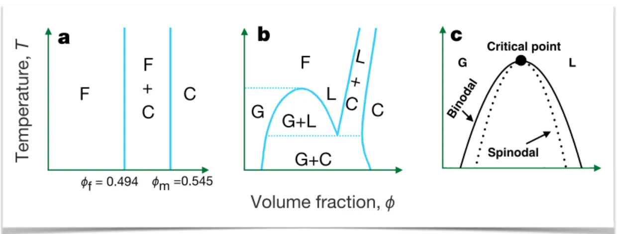
2.2 Equilibrium phases and arrested states . . . 30
2.3 Fractal Gels . . . 35
2.4 Colloidal gels as glassy or jammed materials . . . 37
3 C-S-H growth under precipitation 41 3.1 Introduction . . . 41
3.2 Precipitation and gelation of C-S-H gels: a meso-scale model . . . . 44
3.2.1 Numerical Simulations . . . 47
3.3 Densification: volume fraction and energy . . . 48
3.4 Connectivity and local order . . . 54
3.5 Conclusions . . . 62
4 Equilibrium and kinetically arrested states by varying short-range attractive and long-range repulsive interactions 67 4.1 Introduction . . . 67
4.2 Effective Interactions . . . 68
4.3 Numerical Simulations . . . 70
4.3.1 Molecular Dynamics and Monte Carlo simulations . . . 70
4.3.2 Free energy calculations . . . 71
4.3.3 Grand Canonical simulations . . . 72
4.4 Aggregation at low volume fraction . . . 73
4.4.1 Definitions . . . 74
4.4.2 Clusters morphology and local packing at low volume fraction 74 4.5 Thermodynamic characterization . . . 79
4.6 Morphology and local packing of arrested states . . . 83
4.7 Conclusions . . . 88
5 Structure and mechanics of C-S-H 93 5.1 Introduction . . . 93
5.2 Porosity . . . 94
5.3 Scattering intensity . . . 98
5.4 Mechanical tests . . . 101
5.4.1 Mechanics: Shear Modulus . . . 102
5.4.2 Nanoindentation . . . 104
5.5 Conclusions . . . 107
Concluding remarks and outlook 109
Introduction
Concrete is extensively used in the modern world for infrastructure and buildings due to its mechanical performance and low price. Because of the widespread usage of concrete and the CO2 emission associated with the nature of the material, the manufacturing process needs to be reconsidered. Ideally the concrete production should generate less CO2 emission, while the strength and durability of concrete are maintained or further improved. The production of Portland cement, the main binder of concrete, contributes 5− 7% of all man made CO2, as it represents the largest volumes of building binder material. Even small modifications in the production of cement will reduce substantially the environmental impact of concrete. The underlying scientific questions in cement, where the physics of the microstructure emerge, go far beyond concrete technology.
Cement is the main binding agent of concrete and is produced from limestone and clay, which upon high temperature processing form hard nodules (clinker phase). The clinker is then grounded in presence of calcium sulphates to give the final cement. Calcium-Silicate-Hydrate (C–S–H) is the primary hydration product of Portland cement paste, and it precipitates upon mixing it with water, as nano-scale clusters with an associated internal pore system. These form a gel, i.e. an interconnected disordered structure, which glues together the concrete and is responsible for strength development. Mechanical and viscoelastic behavior of concrete crucially depends on the C–S–H gel and on its own creep behavior due to the evolution (aging) of the local composition and morphology. It has become now clear that the design of high performance and more environmentally friendly cement demands a deeper understanding of physical processes underlying the hydration process, when the calcium-silicate-hydrate (C–S–H) gel develops, and cement sets. In fact, chemical modifications interfere with the formation of the C–S–H gel structure in a way that is not understood and this, in turn, changes also its mechanics.
The understanding of the physics that dominate the first stages of development of mechanical strength in cement, is probably the most significant step towards controlling its properties. The setting, during which the material is transformed from a liquid paste to a soft and finally hard solid, is intimately connected to the hydration process, during which the C–S–H gel is formed. The complicated
evolution with time indicates that the C–S–H gel can have very different cohesion and space filling properties, not only due to initially different chemical composition but also due to the interplay between aggregation and arrested kinetics through the hydration and setting process. The early stages have important effects on the final mechanical behaviour of the solid material but they are very poorly understood. In particular, at present there is no quantitative or qualitative investigation able to account, from the nano-scale components, for the microstructure formation and all the way up to the mechanical response of the material.
This thesis focuses on investigating the hydration and setting of cement at the nano-scale level, using statistical physics models and methods, specifically developed for amorphous materials. Investigating the microstructure formation, its evolution and the arising of mechanical strength of C–S–H hydrate gel over length scales ranging between nm and µm is crucial for the early stages of hydration and setting but is still mainly unexplored. Here, we present a new coarse-grained, particle-based model for cohesive materials, featuring nano-scale components (particles) and specific effective interactions. Moreover, we developed a new numerical approach, a combination of Monte Carlo and Molecular Dynamics numerical simulations, to mimic the precipitation of the C–S–H hydrates and study the development of the microstructure and of the mechanical strength. It is the first time that this type of approach is applied to cement hydration and setting and allow us to address questions as: how does the precipitation rate and/or the cohesive interactions of the nm particles affect the resulting micro-structure of the C–S–H gel? How does the micro-structure of C–S–H gel evolve with time? How does the elastic modulus of the C–S–H gel develop, to what extent is it controlled by the micro-structure and how does it evolves during the hydration?
In particular, our minimal model has few input parameters, such as the effective interaction, the chemical potential and the kinetic rate (which can be though as a production rate of C–S–H). The last two parameters represent the chemical environment during cement hydration and in our model control the out-of-equilibrium conditions of precipitation. The resulting C–S–H gel microstructure is not preimposed but arises from the interplay of effective interactions and chemical conditions through the use of statistical mechanics. Moreover, this approach allow us to compute directly the mechanical properties of the C–S–H gels formed in our simulations and obtain both the time evolution of their microstructure and of their mechanical properties.
This type of approach made it possible to connect the time dependence of C–S–H production to the aggregation process and in addition to investigate the influence of the underlying thermodynamically stable and metastable states to the out-of-equilibrium process of precipitation. We have shown that the evolution of the microstructure of the simulated C–S–H gels displays an accelerating and
a decelerating regime similar to the experimental observations. The former is associated to the formation of thin elongated aggregates that grow and branch or impinge into each other to create a gel, whereas the latter corresponds to the densification of the gel branches that is favored by the underlying thermodynamics. The local packing and the structure organization of the C-S-H particles under precipitation are intimately linked to the equilibrium phase dictated by the effective interactions and by the kinetically arrested states. For this reason, we have also studied systematically the different effective interactions without precipitation and identified their impact in the structure and mechanics of the C-S-H gels under precipitation. Finally, we have been able to compare our results for the evolution of microstructure and mechanics to different experiments. The comparison allow us to rationalize a few aspects of the physics of C–S–H gels and opens new interesting questions.
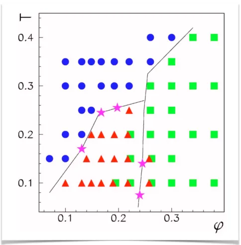
The thesis is organized as follows. In Chapter 1, we give a brief overview on the main concepts in concrete and cement research that are of interest here. This overview focuses on the coupling of cement hydration with the development and evolution of the microstucture and mechanics of C–S–H gel. In Chapter 2, we briefly describe the phenomenology of colloidal gels, starting from the effective interactions and the equilibrium phases underlying the gelation mechanisms and the kinetically arrested states. These two first chapters provide the background for the soft matter perspective that we used to develop our model for growth of C–S–H gels under precipitation. In Chapter 3, we present our model for C–S–H gel formation during the early stages of cement hydration and we discuss the main results of the hydrate precipitation curves, the evolution of the gel morphology and the local packing. We explore further the underlying equilibrium phases and kinetically arrested states with respect to the effective interactions used in our model in Chapter 4, where we analyze this class of interaction potentials on a more general ground. We provide the phase diagrams and discuss how the morphology of the gels changes upon changing the competing attractive and repulsive interactions. In Chapter 5, we attempt a qualitative and quantitative comparison of the model gels with experiments on C–S–H by computing the pore size distribution, the scattering intensity, the evolution of the shear modulus and the nanoindentation modulus. Finally, we summarize the main results and give an outlook for possible future expansions of this work.
Chapter 1
From concrete and cement to
calcium-silicate-hydrate gels
Concrete is the most used manufactured material as it is the cheapest, and has outstanding mechanical performances. Cement is the binder of concrete and C–S–H is the main hydration product of cement which acts as the glue of the material. Understanding the formation of the microstructure of C–S–H is impor-tant for controlling the micro- to macro- scale structure and mechanics of cement. In this thesis, we propose a new model and numerical approach to investigate the formation and evolution of the structure of C–S–H in the meso-scale using experimentally measured forces. In this first chapter, an overview of concrete, cement and mostly C–S–H is presented, focusing on how the hydration kinetics influence the evolution of mechanics, which is the mesoscale and subnano structure of C–S–H and what types of forces act at the nanoscale level of C–S–H.
1.1
Introduction to concrete and cement
The Romans used extensively concrete to build roads, aqueducts and temples that are still holding up remarkably well. The highlight of their construction projects is Pantheon that has the world’s largest unreinforced concrete dome. However, after the end of the Roman empire, the use of concrete became rare until it was re-pioneered in the mid-18th century. In the modern world, concrete is the most used man-made material for infrastructure and buildings, as it is cheap and durable. The remarkable mechanical behavior of concrete is due to its binder, the cement and in turn cement’s mechanical strength is due to Calcium-Silicate-Hydrate (C–S–H) gel [1].
Concrete is an artificial building material composed of water, a binding agent, sand and aggregates such as gravel, chunks of stone, crushed rocks and rubble. The most common binding agent is cement which mixed with aggregates and water eventually solidifies, or "sets". In the beginning the concrete mix
CHAPTER 1. FROM CONCRETE AND CEMENT TO CALCIUM-SILICATE-HYDRATE GELS
is workable, even fluid and easily shaped or poured into molds, and later it solidifies and hardens through a chemical process called hydration. The cement reacts with the water producing a paste that binds the aggregates together into a robust solid material. In addition to these three main components, chemical admixtures may be used to speed or slow down the hardening rate of cement, or re-inforcements as steel may be included in concrete to increase its tensile strength [1].
5 billion metric tons of concrete are consumed each year in the world and these numbers are at the moment only foreseen to increase. From a point of view of natural resources, ecology and economy, it is not possible to imagine substituting concrete by any other material. Despite of the benefits of well-planned concrete usage, the colossal production of Portland cement, the main binder of concrete, has also negative environmental impact as it contributes to 5 − 7% of all man-made CO2. A more sustainable cement production, with less CO2 emission, that is able to retain or even enhance the main properties of concrete like strength and durability is the present challenge of cement research. CO2 production is mostly due to cement processing and to the chemical decomposition of limestone (clinkering). The forefront of research now is therefore towards de-vising strategies to reduce the CO2production within a “do more with less” strategy.
Cement is the most crucial component of concrete as it is responsible for sticking and holding together the aggregates. When cement is mixed with water it rapidly forms a gel which is initially fluid and workable but as the cement sets the gel densifies and becomes rigid, keeping the aggregates in place [2]. Cement paste continues to hydrate for many days after the initial setting. By the end of the curing period concrete achieves the desired mechanical strength. There are also cements that work in a different way and harden by reacting with CO2 in atmosphere (non-hydraulic binders, e.g. slaked limes), but here we will deal only with hydraulic binders that harden by reacting with water, in particular Portland cement [1].
To produce cement, limestone (calcium carbonate) and clay (alumino-silicate) go through high temperature and through sintering form hard nodules of clinker. Initially, the mixture of limestone and clay is ground in a fine powder and then it is placed in a cement kiln, a type of oven that heats up to temperatures of 1450◦C. In the kiln, several processes, such as decarbonation of the limestone, production and transformation of the first calcium silicate and calcium aluminate phases and quenching, take place and finally lead to the clinker [1, 2]. The clinker is ground in presence of calcium sulphates (e.g. gypsum) into a fine powder to give the "Ordinary Portland Cement" (OPC), the most commonly used type of cement. The gypsum (CaSO4 · 2H2O) has a significant effect on cement hydration as it stops the rapid reaction of calcium aluminates, preventing the early hardening.
1.2. CEMENT HYDRATION
Cement is not only the most important ingredient of concrete but also the most energetically expensive. Most of the CO2 associated with cement manufacture is produced from decarbonation of limestone and fuel combustion. In modern cement kilns many advanced features are used to lower the fuel consumption per ton of clinker produced. Cement kilns are extremely large, complex, and polluting industrial installations, with many undesirable emissions. Even advanced and efficient kilns have large energy requirements to produce a ton of clinker and then grind it into cement [1]. The main strategies to reduce the environmental impact of cement consist in using cement in less quantity, more efficiently or in developing smart mixtures. The design of such high performance and more environmentally friendly cements demands a deeper understanding of the hydration process, because this is when the mechanical properties of cement are developed.
The hydration process begins soon after the mixing of cement with water. The clinker is rich in calcium silicates (mainly tricalcium silicate 3CaO· SiO2) and re-acts with water to form calcium-silicate-hydrate (C–S–H), calcium hydroxide and minerals (AFm and AFt phases) [2]. The hydration products can be categorized into polycrystalline, fully dense pore products (e.g. calcium hydroxide) and into amorphous products growing from the unreacted cement particles and forming a connected network (C–S–H). The amorphous C–S–H is the most abundant hydra-tion product, accounting for the 70% of the cement paste volume and it is the most important as it is responsible for the remarkable mechanical properties of cement. More specifically, the percolation of the C–S–H gel through the clinker particles de-termines the rigidity threshold of cement. It is speculated that the early hydration stages of cement, when the primary C–S–H develops till it percolates through the clinker paste, have dramatic consequences on strength and durability of concrete.
1.2
Cement hydration
In Table 1.1 we summarize the main reacting and hydrated phases of cement men-tioning also their name in cement chemistry notation (CCN). Please note that if there is a second name in the first column it refers to the mineral phase. The first four phases are the main reacting phases contained in clinker or non-hydrated cement with C3S being more abundant and the lower part of the table contains the hydration products, all of which apart of C–S–H are crystalline.
1.2.1
The hydration process
The transformation of the liquid cement paste into a soft and finally hard solid, is intimately connected to the hydration of cement. During the process of hydration, a number of chemical reactions with multiple steps take place and different hydration products are formed. Cements (without admixtures) are transformed by 50% into hydrates within 24 hours and by 80% after 28 days. The hydration
CHAPTER 1. FROM CONCRETE AND CEMENT TO CALCIUM-SILICATE-HYDRATE GELS
Table 1.1 Nomenclature of the main reacting and product phases of cement. The last column is the cement chemistry notation (CCN).
Name Molecular formula CCN
Tricalcium silicate or Alite 3CaO· SiO2 C3S Dicalcium silicate or Belite 2CaO· SiO2 C2S Tricalcium aluminate or Aluminate 3CaO· Al2O3 C3A Tricalcium alumino ferrite or Ferrite 4CaO· Al2O3· Fe2O3 C4AF Calcium silicate hydrate (CaO)x(SiO2)(H2O)y C–S–H
Calcium hydroxide or Portlandite Ca(OH)2 CH
Aluminate trisulfate or Ettringite (CaO)6(Al2O3)(SO3)3· 32 H2O
AFt
Aluminum monosulfate 3CaO · (Al, Fe)2O3 · CaSO4· n H2O
AFm
Hydrogarnet 3CaO· Al2O3· 6 H2O C3AH6
reactions can be described as dissolution of the reactive species contained in the clinker and precipitation of hydration products.
The reacting phases of cement are alite C3S, belite C2S, aluminate C3A and ferrite C4AF. The hydration of alite is the main reaction responsible for strength development during the first 24 hours. Alite reacts fast with water so that after 28 days 70% of it has been replaced by hydration products [2]. On the contrary belite hydrates much slower, only 30% has reacted by the end of 28 days. Tricalcium aluminate reacts very fast with water, causing flash setting which reduces the workability of cement paste and obstructs the mixing of cement with water. To avoid this retarders as gypsum is added to clinker. The main hydration products of the clinker are C–S–H and calcium hydroxide, whereas the reaction of calcium aluminate, with gypsum and water produces calcium sulphoaluminates, initially mainly ettringite.
The hydration process can be monitored by techniques ranging from con-ductimetry or calorimetry to nuclear magnetic resonance(NMR) and X-Ray
1.2. CEMENT HYDRATION
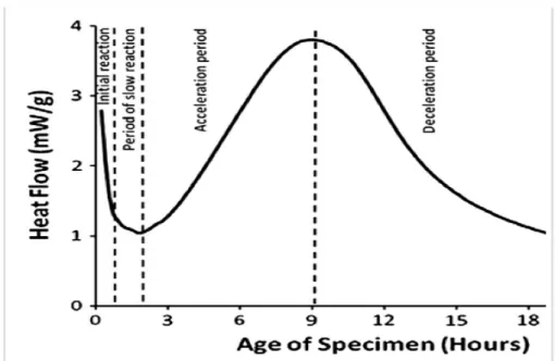
diffraction [2]. In Fig. 1.1, it is shown a typical curve of the heat flow evolution during C3S hydration measured by isothermal calorimetry. From the changes of the heat curve, the hydration can be divided into four periods: the initial reaction, the slow reaction, the acceleration and the deceleration period. Sometimes a fifth period of slow on going hydration is added for times longer than one day. The initial reaction period is characterized by a first peak of heat flow followed by a period of low heat activity called slow reaction period. The heat flow increases until it reaches the maximum rate. This period is called acceleration period and the one following the maximum is the deceleration period [1, 2].
Initial reaction period. The first stage of hydration is characterized by the rapid dissolution of clinker
Ca3SiO5+ 3H2O → 3Ca2++ 4OH−+ H2SiO2−4 (1.1) immediately after the wetting of the clinker powder. In calorimetry measurements, (see Fig. 1.1), a large exothermic signal is measured due to wetting and dissolution of clinker. The wet clinker releases ions such as calcium, silicate and hydroxide to the solution. From the evolution of these ion concentrations the dissolution rate of clinker can be evaluated. The dissolution rate shows an immediate decrease that coincides with the first peak of the calorimetry curve [3]. Moreover, a sharp peak in silicate concentration is also observed, which is followed by a sharp decrease due to the formation of C–S–H nuclei. On the contrary, the calcium and hydroxide concentrations increase as the C–S–H has a lower Ca/Si ratio than the clinker. The pH of the solution increases due to the continuous release of calcium and hydroxide. In addition, ettringite crystals appear due to the dissolution of C3A but portlandite does not precipitate in this stage because the solution is not supersaturated with calcium and hydroxide. Overall, the hydration process shows complex coupling of the chemical reactions and the growth of different crystalline phases.
Period of slow reaction. At the next stage the reactions slow down and the cement paste retains its workability for few hours. There are different hypothesis for what is happening during this period. One is that a metastable layer of precipitates (C–S–H or C–S–H like) is formed around the clinker grains and inhibits further dissolution [3, 4]. However, such a layer has never been observed by direct surface examination, whereas experiments have detected clumps of precipitates on smooth or pitted surface of C3S [3, 5]. Another hypothesis proposes a steady state between slow dissolution of clinker and slow grow of C–S–H [3, 4]. Some experiments also support this hypothesis showing that by addition of C–S–H seeds the slow reaction period can be nearly eliminated and the system proceeds immediately to the accelerating period [6, 7]. The larger the number of C–S–H
CHAPTER 1. FROM CONCRETE AND CEMENT TO CALCIUM-SILICATE-HYDRATE GELS
nuclei or seeds the faster the hydration reaction proceeds.
Fig. 1.1 Heat flow of alite hydration versus the hydration time of the specimen, measured by isothermal calorimetry. The characteristic periods of hydration are indicated.
Acceleration period. After the initial dissolution of clinker leads to a supersat-urated solution with respect to the C–S–H and to a sufficient amount of C–S–H nuclei, fast precipitation of C–S–H occurs at the onset of the acceleration period:
xCa2++ 2(x− 1)OH−+ H2SiO42− → (CaO)x(SiO2)(H2O)y (1.2) where x is the calcium to silicon ratio and y can vary. Reaction 1.2 shows that the stoichiometry of C–S–H is not fixed. The second hydration product is calcium hydroxide (portlandite) which precipitates according to the follow reaction:
Ca2++ 2OH−→ Ca(OH)2 (1.3) C–S–H is less soluble than portlandite, therefore it precipitates faster. Especially at high solution volume (high w/c) portlandite precipitates after the acceleration period.
As the ions in the solution are consumed by the hydration products, the dissolution is accelerated again, increasing the heat release. The C–S–H gel keeps growing, filing the space between the clinker grains when the heat release is maximum [2]. This is the cohesion point and corresponds to what is usually considered the end of the setting.
1.2. CEMENT HYDRATION
Deceleration period. The last stage is the deceleration which begins after the peak of the heat rate and continues until the end of the reaction. By the end of a day the heat rate drops and after 24 hours the hydration continues very slowly. The decrease of the heat rate is associated with the decrease of the C–S–H surface and the thickening of the C–S–H gel around the clinker particles. Scattering experiments showed that the hydration rate is associated with the roughness and the thickness of the hydration products [4, 8].
There are two main hypothesis for the onset of the deceleration period. One suggests that it is controlled by diffusion and the other that is limited by the space filling [3, 4]. According to recent experimental evidence, if the former was true the deceleration should happen at the later ages of hydration and not within the first 24 hours [9]. SEM observations of the microstucture suggest the C–S–H grows in an anisotropic way and forms aggregates with different packing densities. More specifically by AFM examination it is observed that the aggregation of C–S–H occurs mostly perpendicular or parallel to the clinker surface [10]. The impinge-ment of the C–S–H aggregates and the formation of a interconnected network in between the clinker grains reduces the available space for new hydrates [9].
1.2.2
Mechanical properties of cement during hydration
The development and setting of C–S–H change significantly the rheology and the mechanics of the cement paste, initially fluid and eventually hardened. Controlling the rheology of cement is crucial for several applications such as casting and transportation of cement. One of the most demanding applications for cement rheology is the oil- and gas- well cementing, where cement is pumped thousands meters deep into the earth to seal the well and keep in place the casing. In this case, cement should remain pumpable for several hours under high temperature and pressure, while still should set within a reasonable time to allow resumption of operations. Rheological measurements of the viscous properties of cement paste such as flow curves (shear rate versus shear stress), yield stress and viscosity versus shear rate, are very useful for devising the pumping of fresh cement paste. Although fresh cement behaves as a viscous liquid, the hardened cement paste is a solid material with remarkable mechanical strength. To probe the elastic properties of the hardened cement paste, experimental techniques ranging from macroscopic mechanical tests to nanoindentation can be used.
During setting, cement is a viscoelastic material, exhibiting characteristics of both solids and viscous fluids. In particular the way the mechanical strength develops and the crossing from the fluid-like properties to solid-like behaviour are intimately connected to the hydration process. The complex time-dependent rheological response of cement during the hydration is usually monitored by dynamic mode rheometry where the shear modulus versus the hydration time is obtained, as shown in Fig. 1.2 [11]. Three different regimes are observed in the
CHAPTER 1. FROM CONCRETE AND CEMENT TO CALCIUM-SILICATE-HYDRATE GELS
measurement of the shear modulus of cement without admixtures (dashed line of Fig. 1.2): the first increase of stiffness, a dormant period where the change of the elastic modulus is much weaker and the second increase of stiffness.
Fig. 1.2 Time evolution of the shear modulus of cement paste withw/c = 0.8 [11]. Dashed and solid line correspond to sample without and with superplasticizers respectively. The horizontal line indicates the minimum significant detection level.
Almost immediately after cement is mixed with water, the shear modulus increases to 107Pa, which corresponds to the first increase of stiffness of Fig. 1.2 and it is a clear sign of an initial gelation. At this point the degree of hydration is zero [12] but the cement paste has a measurable yield stress. This first increase occurs during the initial reaction period of the hydration when the clinker particles are sticking together and form a weak network, due to high ionic strength of the interstitial solution. The aluminates have also an important role in this stage [2]. The gel structure is relatively weak and is easily destroyed by vibration, although, if not disturbed, it does not change during the next hours [13]. After this first weak gelation the shear modulus stays at the plateau of 107Pa for nearly five hours, which correspond to the dormant period of Fig. 1.2. The length of this period coincides with the period of slow reaction and the first two hours of the acceleration period. The addition of admixtures avoids this initial plateau and makes the cement retain its fluidity.
The second increase of stiffness signals the setting of cement and its trans-formation into a solid material. During the dormant period the nuclei of C–S–H increase in number, preparing the right conditions for fast growth of C–S–H during the acceleration period. The second increase of the shear modulus happens at the same time as the acceleration period of the hydration, when the initial network of
1.3. STUCTURE OF CEMENT AND C–S–H
clinker particles gets reinforced with C–S–H. The densification of the C–S–H layers around the clinker particles continues and by the end of the second increase, when the acceleration period also finishes, the shear modulus has reached the range of GPa due to the mechanical percolation of the C–S–H gel among what is left of the clinker particles. Finally, further hardening occurs over periods from weeks to years due to further hydration and long term rearrangements of the structure over different length scales.
It is clear that cement hydration influences directly the rheology and the development of mechanical strength of cement. Although cement hydration has been the subject of extensive investigation, there are still many issues that are controversial or poorly understood. A particular interesting open question is the linking of the chemical kinetics to the microstucture of the C–S–H and to the evolution of the mechanical properties of cement [4]. The complicated evolution of the microstructure with time indicates that the C–S–H gel can have very different cohesion and space filling properties, not only due to different chemical composition but also due to the interplay between aggregation and arrested kinetics through the hydration and setting process. In particular, at present there is no quantitative or qualitative investigation able to account, from the nano-scale components, for the microstructure formation and all the way up to the mechanical response of the material.
1.3
Stucture of cement and C–S–H
The microstructure that C–S–H forms, the way it evolves and the cohesive forces that hold it together are very important for the mechanical response of the final material. An important unresolved issue in cement research is how to rationalize the formation and structure of C–S–H gel from the molecular scale to the macroscopic scale. As we mentioned before, cement paste itself has a complex structure from the macroscale to the nanoscale. It is composed by different phases of crystalline hydrated products such as Portlandite, AFm and AFt phases, unhydrated clinker particles polydisperse in size, all bound together by the amorphous C–S–H. The initial network, that the clinker particles form as soon as they are mixed with water, provides an initial heterogeneous structure around which hydrates of different sizes and structure grow. In this section, the main characteristics of the C–S–H structure as seen from the macro, meso and nanoscale are presented in more detail.
Looking at the cross section of a concrete block, two phases are distinguished: the aggregates of polydisperse size and shape and the binder, the cement matrix. At the level of few centimetres the cement matrix is fairly homogeneous compared to the aggregates, however a closer look at the level of millimetres reveals the
CHAPTER 1. FROM CONCRETE AND CEMENT TO CALCIUM-SILICATE-HYDRATE GELS
heterogeneous structure of cement. For example pores of diameter 0.1− 5mm can be observed which maybe caused due to trapped air and loss of water during the hydration.
The porosity in cement is usually measured by two types of experimental techniques: one type involves the intrusion of a fluid into the pore system (mercury intrusion, pyknometry, gas sorption isotherms) and the other use particles or fields to probe the material (small-angle neutron scattering (SANS), NMR). The latter techniques can be used even on non dried samples. To achieve more microscopic information on the structure other common techniques used to image the cement structure are electron microscopy techniques such as scanning electron microscopy (SEM) and transmission electron microscopy (TEM), atomic force microscopy (AFM) and scattering techniques such as SANS and small-angle X-ray scattering (SAXS). The mineralogical composition can be identified by X-ray diffraction (XRD) and the chemical composition can be identified by X-ray fluorescence (XRF) and energy-dispersive X-ray spectroscopy (EDS). Using these techniques a more detailed picture of the structure of cement at smaller scales is obtained [1, 14].
1.3.1
Mesoscale structure of cement paste and C–S–H
Cement has a rich multi-phase composition at the scale below millimeter. One can distinguish the microscale (mm− µm) from the nanoscale (µm − nm) domains. At the level of the microscale many crystalline phases are observed together with the amorphous C–S–H. The most common crystal is the portlandite which can grow up to several micrometers in the pore solution and close to the particle surface. The size of the portlandite crystals depends on the temperature and w/c ratio. The ones growing in the pore solution under ideal conditions form hexagonal plates, whereas the ones growing close to the clinker surface are not perfectly shaped. Other crystal phases are the AFm and AFt, which form needles of around one micrometer close to the clinker particles [14].
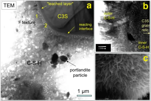
In the beginning of the hydration, C–S–H grows loosely around the clinker phase starting from nuclei, later it densifies and glues together also the crystalline phases. Fig. 1.3a shows a TEM picture of a hydrating particle of alite, surrounded by C–S–H and portlandite. The morphology of C–S–H can vary from globules, to fibril or foil-like depending on the initial conditions and the hydration stage [15]. The initial composition of cement powder, the w/c ratio, the relative humidity are some of the parameters that influence the C–S–H structure. The fibril growth has been suggested to rise from increased osmotic pressure that ruptures the pre-existing C–S–H layer [15, 16]. Jennings and co-workers investigated the size and diameter of the needles formed under different conditions of relative humidity [17]. The ESEM picture of Fig. 1.3c shows such fibrillar outer product of a rapidly dried sample after three days of hydration. Different growing directions
1.3. STUCTURE OF CEMENT AND C–S–H
of the C–S–H are also found in microscopy pictures. C–S–H grows both outwards and inwards the clinker particles, forming the so called inner and outer product respectively. The inner product occupies the space of the hydrating grain and its structure is more compact and amorphous. The outer product is formed in the pore solution and it is reported to form bumps, needles or foils. In the TEM image of Fig. 1.3b, the features of inner and outer foil-like C–S–H can be distinguished [18].
C3S
C-S-H TEM view of the arrested
reaction of tricalcic silicate (C3S - Alite) transforming to calcium silicate hydrate Oversimplified cement approximate reaction: Ca3SiO5 + 5.3 H2O ---> (C3S) Ca1.7SiO3.7 4(H2O) (C-S-H) + 1.3 Ca(OH)2 portlandite 1 µm 1 2 texture portlandite particle TEM
ion -thinned sample
reacting interface "leached layer" "High-density" C-S-H = hdC-S-H "Low-density" C-S-H = lath-like C-S-H = ldC-S-H elongated normal to the resorbing C3S C3S grain relic inner C-S-H outer C-S-H
presents an amorphous morphology typical of an incrementally dried younger sample.
The micrographs show a trend that, in early-age C3S paste samples,
a distinct fibrillar structure of C–S–H emerges when the samples were subjected to higher rates of drying. In contrast, slower drying rates produce a microstructure that is less distinct, as observed in the ESEM. Based on these results, it follows that, to some degree, the morphology of C–S–H may be a consequence of drying rate. Because the internal volume of large concrete structures does not experience high rates of drying similar to Samples 1–3 and Sample 5, an early-age C–S–H product may more closely resemble the amorphous morphology shown in the incrementally dried specimen inFig. 4.
3.2. Resolution of features
When drying C3S paste in the ESEM, very few microstructural
changes are shown below 80% RH. We also know that irreversible shrinkage in cement paste occurs when the samples are subjected to environments between 50% and 100% RH. This shrinkage must correspond to at least some of the microstructural changes observed here.
Consider the smallest features resolved by the ESEM to explain this phenomenon. At best, one can resolve features that are roughly 10 nm in size. This pore size is approximately the size of the largest gel pores. Using Kelvin's equation
lnpp
o=
2γVm
rRT ð1Þ
where p/pois the partial pressure, γ=0.0728 N/m is the surface
tension, Vm=1.802E-5 m3/mol is the molar volume, R= 8.314 Nm/
Kmol is the universal gas constant, r is the radius of a pore, and T is the temperature, and substituting T =278.15 K (5∘C) into (1), we can
calculate that pores greater than 10 nm in diameter are empty at partial pressures on or below 77%. This condition would explain why few changes are visible in the microstructure when lowering the partial pressure below 80%. Furthermore, because it is not currently possible in the FEI Quanta ESEM to see morphological changes in C– S–H at resolutions better than 10 nm (at low vacuum), the fine nanostructure in its natural state cannot be directly seen. 3.3. Older samples and the mechanism of morphology formation
The trend that rapid drying rates produce a fibrillar C–S–H morphology whereas slower drying rates produce a more amorphous morphology is not replicated in mature samples. As shown inFig. 6, the experiment cannot be reproduced for incrementally dried C3S
paste specimens approximately 21 days into hydration. Instead, these specimens show a mixed result, with about 50% of the image presenting a fibrillar morphology, and the rest with an amorphous morphology typical of an incrementally dried younger sample. At this point, the fibers shown may have naturally formed. These observa-tions support a mechanism where colloidal particles condense and rearrange into different morphologies[34] [35]. Jennings has proposed a model of C–S–H as an aggregation of precipitated colloidal particles[36]with a similar mechanism. In this model, during the early stages of reaction, nanoscale C–S–H particles loosely pack but rearrange and condense during drying. The mixed morphology of older incrementally dried C3S paste specimens suggests that, during
hydration, a fibrillar product may naturally form (i.e. without drying), particularly in the more open regions.
3.4. Irreversible changes to the C–S–H morphology
We hypothesize that an irreversible change occurs during rapid drying and that these changes are most dramatic at early ages. To
Fig. 1. Sample 1: Micrograph of an oven-dried C3S paste imaged at 33% RH. The C–S–H
product in this image presents a fine needlelike morphology.
Fig. 2. Sample 2: Micrographs of C3S paste hydrated for 3 days before rapidly drying
from 100% RH to 33% RH in the ESEM. (a) Several C3S particles encased in C–S–H at a relatively low magnification. (b) Higher magnification of a fibrillar structure of C–S–H. The C–S–H product in this sample presents a fibrillar structure similar to the oven-dried sample (Sample 1), except that Sample 2 has thicker needles.
1676 P.C. Fonseca, H.M. Jennings / Cement and Concrete Research 40 (2010) 1673–1680
"High-density" C-S-H = hdC-S-H "Low-density" C-S-H = lath-like C-S-H = ldC-S-H elongated normal to the resorbing C3S C3S grain relic inner C-S-H outer C-S-H
a
b
c
Fig. 1.3 a) TEM image of alite hydration, transforming into C–S–H. Portlandite crystals have also precipitated [18]. b) TEM image of inner, compact and outer, foil-like C–S–H [18] c) ESEM image of fibrillar C–S–H produced during 3 days hydration of alite and then rapidly dried from 100% relative humidity to 33% [17]
A complementary way to examine the structure of cement is by the characteri-zation and distribution of the void space in the material. The initial amount of water influences significantly the overall porosity of the material, the higher the w/c ratio the more porous the material. Initially the voids in cement are big and connected, however as the hydration proceeds and the solid structure percolates, the pores reduce in size and get disconnected. Initial big capillary pores of few µm are replaced by pores of few decades of nm at the later stages or in the cured paste. Proton NMR spectroscopy is a powerful tool to identify location and chemical environment of water in a complex matrix [19]. Its recent application to cement has given interesting insight into the pore size distribution [20–24]. More specifically, the experiments indicate the presence of pores of 2− 5nm and 14− 30nm, both associated with the C–S–H gel.
Observing the structure of C–S–H at the level of nanoscale is challenging. From the current experimental techniques the nanoscale stucture of C–S–H is
CHAPTER 1. FROM CONCRETE AND CEMENT TO CALCIUM-SILICATE-HYDRATE GELS
not completely elucidated. However, there are some features that are commonly accepted and observed with different techniques. These are the existence of an interconnected network, basic units of characteristic length of few nm with ordered inner structure, pores of few nm and the high specific surface of the C–S–H. In order to interpret the experimental findings of the C–S–H structure, models were developed based either on the hypothesis of the planar grow of natural occurring minerals of tobermorite, jennite and portlandite or on the aggregation of colloidal particles to form a gel. [14]
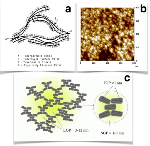
According to the hypothesis of natural minerals, the C–S–H gel is formed by interconnected layers that are similar to mineral crystals [25, 26]. A schematic representation of the picture proposed by Feldman and Sereda is shown in Fig. 1.4a, where the layers are irregularly stacked and water is trapped in between them or adsorbed in the free surfaces. This hypothesis could explain some properties of the nanostructure such as the observed variable composition of Ca/Si ratio, the crystalline regions and the amorphous layers and they were validated by gas sorption properties, porosity and shrinkage. Gartner described the layers as narrow ribbon-like with random defects that make them wavy and cause them to separate and branch. The growth rate of these ribbons was considered exponential assuming that, due to the kinetics of the hydration, nucleation and growth of the new material happens at the extremities of the ribbons. The flat areas of the ribbon layers form nanocrystalline regions [27]. Gartner suggested that the growth of the ribbons and their branching or impingement could correspond to the acceleration and deceleration regime respectively of the kinetics hydrations (see Fig. 1.1) [27].
A picture that is considered complimentary to the one just described is the so called "colloidal model" [28–30] where the basic building blocks of the gel are solid particle of few nm that form aggregates. The interstices among these particle are the gel pores at the size of few nm and are different from the larger capillary pores that are due to the space which is not yet filled by hydration products. The C–S–H particles have an inner crystalline structure and peculiar shape. This first description by Powers and Brownyard in the 50s was based on evidence from water sorption isotherms and total and non-evaporable water [28].
The main indication of the colloidal nature of C–S–H came with the SANS experiments of Allen in the 80s. The scattering data of a hydrating cement paste showed a characteristic length of∼ 5nm after the induction time and a correlation length ∼ 40nm developing due to aggregation [29]. Based on these scattering measurements and sorption data, Jennings proposed a hybrid model of globules with peculiar shape and inner structure. According to his first colloidal model (CM-I), these particles form aggregates with two different packing densities: high density (HD) C–S–H and low density (LD) C–S–H [30]. A further refinement of
1.3. STUCTURE OF CEMENT AND C–S–H
Jenning’s model (CM-II) accounted for the smallest pores of the C–S–H arising from the internal structure of the globules, that like in the picture proposed by Feldman and Sereda, are composed of tobermorite and/or jennite sheets and water. Therefore, the CM-II combines a layer-like structure into the colloidal-like description and achieves to interpret the adsorption isotherm experiments and processes like creep and shrinkage [31]. Fig. 1.4c shows a schematic representation of the colloidal C–S–H particles forming a gel structure with large gel pores (LGP) of 3− 12nm and small gel pores (SGP) of 1 − 3nm due to the defective stacking of the globules. The globules itself are made of horizontal crystalline layers and intra-globular gel pores (IGP) smaller than 1nm are also present.
The aggregation of C–S–H particles was also investigated by AFM imaging of a hydrating surface of alite [32, 33]. An AFM image with C–S–H nanoparticles of dimensions 60 × 30nm2 and 5nm thick that compose the C–S–H gel is shown in Fig. 1.4b. The crystalline structure of these small lamellae results to a defined diffraction pattern with broadened diffraction lines either due to the small size of coherent domains and/or due to defects. Recent SANS experiments confirmed the lamellar structure and determined the thickness of calcium silicate layers and of the water [34].
1.3.2
Subnano structure of C–S–H
Many experimental techniques have been used to elucidate the structure of C–S–H. The main findings of the subnano structure of C–S–H comes from models trying to interpret the experiments of X-ray diffraction (XRD), sorption, shrinkage, NMR and AFM. In the 50s based on XDR evidence Bernal [36] suggested that C–S–H has a layered structure related to a crystalline mineral, 1.1 − nm tobermorite (C5S6H5) and called it tobermorite gel.
In general one observes different types of amorphous C–S–H with variable stoichiometry characterized by the water content and the calcium to silicon ratio (Ca/Si) that ranges from 1.2 to 2.3. C–S–H is usually described as amorphous due to its X-ray diffraction (XRD) patterns that show few broad and weak maxima. However, it has structural similarities with jennite and tobermorite mineral crystals [37]. These minerals have a lamellar structure of calcium oxide layers connected on both sides by silicate chains following Dreierketten arrangement [38]. The main difference of C–S–H that forms during cement hydration is the smaller Ca/Si ratio. Hence, the first atomistic models randomly substituted silicate ions in the mineral with hydroxide groups, with the interlayer space containing strongly absorbed water and additional calcium atoms [39–41]. These models could qualitatively describe gas sorpion and shrinkage but failed to describe the viscoelastic response (creep) of C–S–H and the relative humidity changes (drying shrinkage). In addition, they do not capture the Ca/Si ratio and the density of C–S–H.
![Fig. 1.2 Time evolution of the shear modulus of cement paste with w/c = 0.8 [11].](https://thumb-eu.123doks.com/thumbv2/123doknet/14503448.719689/24.892.170.678.303.599/fig-time-evolution-shear-modulus-cement-paste-w.webp)