RESEARCH OUTPUTS / RÉSULTATS DE RECHERCHE
Author(s) - Auteur(s) :
Publication date - Date de publication :
Permanent link - Permalien :
Rights / License - Licence de droit d’auteur :
Bibliothèque Universitaire Moretus Plantin
Institutional Repository - Research Portal
Dépôt Institutionnel - Portail de la Recherche
researchportal.unamur.be
University of Namur
Using the Event Calculus to Reason about Problem Diagrams
Classen, Andreas; Laney, Robin; Tun, Thein Than; Heymans, Patrick; Hubaux, Arnaud
Published in:
Proceedings of the Third International Workshop on Applications and Advances in Problem Frames
(IWAAPF'08), co-located with ICSE'08
Publication date:
2008
Document Version
Early version, also known as pre-print
Link to publication
Citation for pulished version (HARVARD):
Classen, A, Laney, R, Tun, TT, Heymans, P & Hubaux, A 2008, Using the Event Calculus to Reason about
Problem Diagrams. in L Rapanotti, G Jon, H Zhi & J Karl (eds), Proceedings of the Third International Workshop
on Applications and Advances in Problem Frames (IWAAPF'08), co-located with ICSE'08. ACM Press, pp.
74-77.
General rights
Copyright and moral rights for the publications made accessible in the public portal are retained by the authors and/or other copyright owners and it is a condition of accessing publications that users recognise and abide by the legal requirements associated with these rights. • Users may download and print one copy of any publication from the public portal for the purpose of private study or research. • You may not further distribute the material or use it for any profit-making activity or commercial gain
• You may freely distribute the URL identifying the publication in the public portal ?
Take down policy
If you believe that this document breaches copyright please contact us providing details, and we will remove access to the work immediately and investigate your claim.
Using the Event Calculus to Reason about Problem Diagrams
Andreas Classen
∗PReCISE Research Centre Faculty of Computer Science
University of Namur 5000 Namur, Belgium
[email protected]
Robin Laney
Centre for Research in Computing The Open University Milton Keynes MK7 6AA, UK
[email protected]
Thein T. Tun
Centre for Research in Computing The Open University Milton Keynes MK7 6AA, UK
[email protected]
Patrick Heymans
PReCISE Research Centre Faculty of Computer Science
University of Namur 5000 Namur, Belgium
[email protected]
Arnaud Hubaux
PReCISE Research Centre Faculty of Computer Science
University of Namur 5000 Namur, Belgium
[email protected]
In Proceedings of the 3rd International Workshop on Advances and Applications of Problem Frames (IWAAPF’08). Co-located with ICSE 2008 Leipzig, Germany, May 2008.
ABSTRACT
Central to the problem frames approach is the distinction of three different descriptions: requirements R, domain as-sumptions W and specifications S, tied together with the so-called frame concern, a proof obligation that has to hold be-tween them if a problem diagram is to be correct: S, W ` R. The form this proof should take is not fixed a priori. It might, however, be desirable to automate it in order to al-low for an efficient analysis of large diagrams. To make this possible, we follow some earlier suggestions to use the Event Calculus as a suitable formalism for these descriptions. The main contribution of the present paper is a set of consis-tency rules as well as guidelines for passing from a problem diagram to its formal description.
Categories and Subject Descriptors
D.2.1 [Software Engineering]: Requirements/Specifica-tions—Languages, Methodologies, Tools
General Terms
Design, Documentation, Languages
1.
INTRODUCTION
A problem diagram [7] is made up of requirements, real-world domains, a machine and the links of phenomena they share. Jackson acknowledges that those elements of a di-agram need to be described in further detail, i.e. by de-scriptions R, W and S, respectively. However, he does not fix the form these descriptions should take. In addition,
∗
FNRS Research Fellow
Permission to make digital or hard copies of all or part of this work for personal or classroom use is granted without fee provided that copies are not made or distributed for profit or commercial advantage and that copies bear this notice and the full citation on the first page. To copy otherwise, to republish, to post on servers or to redistribute to lists, requires prior specific permission and/or a fee.
IWAAPF’08,May 10, 2008, Leipzig, Germany. Copyright 2008 ACM 978-1-60558-020-3/08/05 ...$5.00.
there is the so-called frame concern, a fundamental relation-ship between them introduced by Zave and Jackson in [18] which has to hold for a diagram to be considered correct: S, W ` R. Again, the way this proof is discharged depends on the form of the descriptions, and vice-versa. Given the wide range of choices, there have been several suggestions as to how to represent those detailed descriptions of a problem diagram. Hall et al. use their own event model [4], Laney et al. use a mix of natural language and pseudo-code [9], Seater and Jackson use the Alloy Analyser and its language [16], Salifu et al. suggest to use state-charts [15], and others the Event Calculus [10, 11, 1, 2]. Each of these formalisms has its advantages and limitations, and in the present paper we focus on those of the Event Calculus (EC).
A key aspect of the previous approaches using the EC is the idea of providing EC descriptions for the elements of a problem diagram in order to reason about problem proper-ties. Yet, they do not detail how to get from a diagram to its EC formalisation, nor what the relation between them is. With the present paper, we intend to fill this gap by explaining clearly how the EC can be used as a “problem description language”. In this, we consolidate the existing work by suggesting consistency rules and guidelines for for-malising problem diagrams with the EC. The contribution of this paper is thus an approach that defines a standard for representing problem diagram descriptions in the EC and opens new possibilities for description reuse and/or sharing. The paper is structured as follows. Section 2 gives a brief overview of the EC. In Section 3 we first survey the exist-ing uses of the EC in the problem frames (PFs) community and then introduce our standard method. We discuss ad-vantages and limitations of using the EC in Section 4 before concluding the paper in Section 5.
2.
THE EVENT CALCULUS
The EC was originally introduced by Kowalski and Ser-got [8] as a formalism for representing events and their ef-fects. The EC version we use is based on Mueller [13] and Shanahan [17]. EC descriptions express relations be-tween fluents, events and time points. Fluents are generally boolean properties but can also be integer or real values.
Events are incidents that occur at specific time points, they can cause changes to fluents, or other events. Time points are simply integer values in discrete EC and real values in normal EC.
The EC builds on first-order predicate calculus. There are a number of predefined predicates, related by a set of axioms, that allow us to express descriptions. These pred-icates are represented in the upper part of Table 1. The Happens predicate allows us to express what happens when; Initiates, T erminates and Releases express the effects of events; and ReleasedAt and HoldsAt describe when fluents hold. According to the common-sense law of inertia [13], a fluent subject to inertia can only be changed by the occur-rence of events. A fluent released from inertia can change at will. Integer or real typed fluents as well as time points can be compared and manipulated using the common operators of the natural or real numbers.
Table 1: Predicates and axioms of the discrete EC, adapted from [17, 13].
Predicate Description
Happens(a, t) Action a occurs at time t
Initiates(a, f, t) Fluent f starts to hold after event a at time t
T erminates(a, f, t) Fluent f ceases to hold after event a at time t
HoldsAt(f, t) Fluent f holds at time t
Releases(a, f, t) Fluent f is released from inertia after event a at time t
ReleasedAt(f, t) Fluent f is released from inertia at time t
Axioms (EC1) HoldsAt(f, t + 1) ⇐
HoldsAt(f, t) ∧ ¬ReleasedAt(f, t + 1))∧ ¬∃e • (Happens(e, t) ∧ T erminates(e, f, t)) (EC2) HoldsAt(f, t + 1) ⇐
Happens(e, t) ∧ Initiates(e, f, t) (EC3) ¬HoldsAt(f, t + 1) ⇐
¬HoldsAt(f, t) ∧ ¬ReleasedAt(f, t + 1))∧ ¬∃e • (Happens(e, t) ∧ Initiates(e, f, t)) (EC4) ¬HoldsAt(f, t + 1) ⇐
Happens(e, t) ∧ T erminates(e, f, t)) (EC5) ReleasedAt(f, t + 1) ⇐
ReleasedAt(f, t) ∧ ¬∃e • (Happens(e, t)∧ (Initiates(e, f, t) ∨ T erminates(e, f, t))) (EC6) ReleasedAt(f, t + 1) ⇐
Happens(e, t) ∧ Releases(e, f, t)) (EC7) ¬ReleasedAt(f, t + 1) ⇐
¬ReleasedAt(f, t)∧
¬∃e • (Happens(e, t) ∧ Releases(e, f, t)) (EC8) ¬ReleasedAt(f, t + 1) ⇐
Happens(e, t)∧
(Initiates(e, f, t) ∨ T erminates(e, f, t)) Coherence of these predicates is guaranteed by a set of axioms, shown in the lower part of Table 1, which implement the informal descriptions stated before. The axioms given are those for the discrete EC; the axioms for the normal EC are similar. The first one (EC1) says that a fluent f holds
at time t + 1 if it held and was not released from inertia at time t and if it was not terminated by an event at time t. In addition to that, (EC2) states that a fluent also holds at t + 1 if it was initiated by an event at t. The remaining axioms are very similar, (EC3) and (EC4) express when a fluent does not hold and (EC5) through (EC8) give the same properties but for the ReleasedAt predicate.
3.
FROM A PROBLEM DIAGRAM TO
EVENT CALCULUS FORMULAE
Laney et al. [10] first used the EC to derive specifica-tions from requirements and domain assumpspecifica-tions. Laney et al. use the EC as a means to reason about inconsistent re-quirements and to solve interactions by prioritising these requirements [11]. Classen et al. [1, 2] use the EC to for-malise problem diagrams that detail features of a product line in order to detect interactions between features.
One important pattern that can be recognised from EC us-age in the above proposals is the coherence between shared phenomena defined on a problem diagram and the fluents and events used in the corresponding EC formulae: the flu-ents and evflu-ents used in the formulae generally exist as shared phenomena in the problem diagram. Based on this observa-tion, we will propose a set of consistency rules and general principles in Section 3.1 which we illustrate using the traffic light controller example in Section 3.2.
3.1
Towards a standard form
The observed pattern actually leads to the first of three consistency rules:
(C1) Structural consistency. A set of formulae is associ-ated to a problem diagram. Each formula is associassoci-ated to exactly one domain or requirement of the diagram. (C2) Vocabulary consistency. Fluents and events in the EC formulae associated to a diagram are identified by their name which must be unique. These names have to refer to shared or internal phenomena of domains in the diagram.
(C3) Scope consistency. All events and fluents used in a formula have to be visible to its associated domain (i.e. they exist on its shared phenomena links or are internal to that domain).
The purpose of these rules is to make sure that the formal description is actually consistent with the problem diagram. More precisely, they require the formulae to be a refinement of the diagram. Without such rules it would be possible to write formulae that have a vocabulary and a structure com-pletely disjoint of the diagram. With these rules, we also guarantee a certain modularity at the description level. Be-cause of the predefined interfaces between domains, and by the principle of information hiding [14], each domain can be described separately and its description be independent from the other domains. In addition, the consistency rules value the decomposition of the problem diagram as it dictates the structure of the formal descriptions, thereby facilitating also traceability.
Based on these rules, we propose two general principles. They are particular patterns of formulae intended to be guidelines for writing formulae:
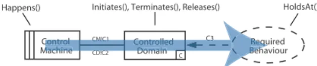
(G1) Type principle. Phenomena expressing single oc-currences or actions rather than properties should be trans-lated into events in EC descriptions. Phenomena represent-ing properties of domains, on the other hand, should be-come fluents. For instance, requirements phenomena refer-ring to properties of the real world would become fluents and requirements phenomena referring to user actions be-come events. Note that Jackson [7] also identifies different types of phenomena on the annotations of basic PFs, namely causal phenomena (C), symbolic phenomena (Y) and event phenomena (E). Given this classification, causal phenom-ena can translate into either fluents or events, depending on how the causal relationship is expressed, symbolic phenom-ena translate into fluents and event phenomphenom-ena into events. (G2) Flow principle. EC descriptions should reflect the active, reactive or passive nature of a domain, as presumed by the applicable frame (its control flow ). For a required behaviour PF, for instance, the control flow goes from the left to the right as depicted in Figure 1. The machine has to bring about changes in the environment—it is active. Its specification will thus probably be written with Happens() predicates, as only events can cause changes to fluents and because the specification phenomena will likely be events. The requirement, on the other hand, is passive. It will be expressed in terms of requirements phenomena, probably flu-ents, and is thus expressed with HoldsAt() predicates. The domain then serves as a relay between the other two (it is reactive), thus expressing the effects of the specification’s events on the requirement’s fluents using Initiates(), Termi-nates() or Releases() predicates.
Control
Machine CD!C2 BehaviourRequired
C3
CM!C1
C
Controlled Domain
Initiates(), Terminates(), Releases() HoldsAt() Happens()
Control Machine CD!C2
C3 CM!C1 Controlled
Domain BehBehReqRequ
Figure 1: Control flow and derived usage of EC predicates in the required behaviour PF.
Note that there may be situations to which principles G1 and G2 do not apply. In practice, however, we found that they are very helpful as a starting point
3.2
Illustration
As a small illustration we will use Jackson’s traffic lights controller example [7]. A traffic light unit has a stop and a go light, the meaning of which is supposed to be known to road-users. There are two such units, one at each end of a single lane supposed to carry traffic in both directions. A controller is connected to both units, which has to activate the stop and the go light so that vehicles are never travelling in both directions at the same time. A problem diagram for this example, also taken from [7], is depicted in figure 2.
Lights
controller a Lightunits b regimeLights Specification Domain properties Requirement
a: LC! {RPulse[i], GPulse[i]} b: LU! {Stop[i], Go[i]} c
Figure 2: The traffic lights controller.
The light units domain description says how the light units react to the RPulse and GPulse events received by the con-troller. For this, we consult the manual that came with the light units. We assume that it says (W1) RPulse switches off the Go light and switches on the Stop light, (W2) GPulse switches off the Stop light and switches on the Go light as well as (W3) both lights will never be switched on at the same time. Following G1, we assume RPulse and GPulse to be events because they occur at specific time points and be-cause they influence Stop and Go. The latter, on the other hand, are fluents as they are properties that can be observed. These definitions indeed satisfy C1, C2 and C3. The actual domain description follows quite naturally:
(W 1)∀t, i = 1..2 • Initiates(RP ulse[i], Stop[i], t) ∀t, i = 1..2 • T erminates(RP ulse[i], Go[i], t) (W 2)∀t, i = 1..2 • Initiates(GP ulse[i], Go[i], t)
∀t, i = 1..2 • T erminates(GP ulse[i], Stop[i], t) (W 3)∀t, i = 1..2 • HoldsAt(Go[i], t) ⇒ ¬HoldsAt(Stop[i], t)
∀t, i = 1..2 • HoldsAt(Stop[i], t) ⇒ ¬HoldsAt(Go[i], t) The requirement expresses the light regime, i.e. the fact that one light unit displays the start light for a certain time, say 50 seconds, and then switches to the stop light. After a delay of 10 seconds, the other unit does the same, and after another 10 seconds the cycle restarts. Each cycle thus takes two minutes. We assume that the time in EC formulae is represented in seconds. All fluents being defined, we can immediately express the formal requirement:
(R) ∀t • t mod 120 = 0 ⇒ HoldsAt(Go[1], t) ∧ HoldsAt(Stop[2], t) ∧ HoldsAt(Stop[1], t + 50) ∧ HoldsAt(Go[2], t + 60) ∧ HoldsAt(Stop[2], t + 110) We can now derive a specification for the machine using the axioms introduced above. Actually, (EC1) and (EC2) state that a fluent holds if it already held the moment be-fore and was not terminated or released, or if it was initiated the moment before. This means that in order to have Go[1] holding at time t, we need GP ulse[1] to happen at t − 1. More precisely, refining the requirement can be done by us-ing the axioms of Table 1 as rewritus-ing rules. The result of the refinement is the EC specification of the machine: (S) ∀t • t mod 120 = 0 ⇒ Happens(GP ulse[1], t − 1)
∧ Happens(RP ulse[2], t − 1) ∧ Happens(RP ulse[1], t − 1 + 50) ∧ Happens(GP ulse[2], t − 1 + 60) ∧ Happens(RP ulse[2], t − 1 + 110)
4.
DISCUSSION AND FUTURE WORKS
One of the main benefits of using the EC is its ease of use for expressing properties of the real world when those properties mostly consist of cause/effect relations [13]. In addition, the meaning of EC predicates is rather straight-forward, resulting in a lower learning curve than for other formalisms of temporal logic. This also makes it relatively easy to translate a natural language description into formu-lae. Another benefit of using a formal language such as the EC is its amenability to automated reasoning. Several im-plementations of the EC exist. We chose Mueller’s Decrea-soner [13] and implemented an Eclipse plugin on top of it (available at www.classen.be/work/mscthesis). The plugin
actually features a dedicated EC editor, an augmented De-creasoner syntax with constructs for distinguishing S, W and R as well as a push-button interface for performing proofs of the type S, W ` R. Yet another benefit, as proposed by Laney et al. [10, 11] and as demonstrated in Section 3.2, is the possibility to derive a correct specification from the requirement and the domain properties through abductive reasoning. Proceeding this way has the advantage that the specification obtained satisfies the S, W ` R relation by con-struction, making a proof unnecessary. It also matches the PF semantics [5] in that S is determined by W and R.
Most limitations can be seen as restrictive ontological com-mitments. The discrete EC assumes (i) that the time is linear and (ii) that it is discrete. The latter is actually no restriction in expressiveness as discrete and continuous EC are provably equivalent [13], but can pose problems in terms of “naturalness” of a description. The first point, however, is indeed a restriction because branching time calculi such as the situation calculus [12] are more expressive than linear time calculi (reasoning about hypothetical events and situa-tions, for instance). Furthermore, EC descriptions generally do not distinguish between input and output of the mod-elled system, as other formalisms such as statecharts do. It is thus not possible to verify whether the system can actually accept every possible input. Pre-/Post-condition reasoning is also rather hard to do in the case of the EC.
In an attempt to validate our proposal, i.e. the claimed advantages of the EC as well as the suggested guidelines, we are planning field experiments with MSc students.
5.
CONCLUSION
Based on what we found in the literature we defined a set of consistency rules and guidelines for the formalisation of a problem diagram using the EC. The goal of this proposal is twofold. On the one hand, we intend to provide a reference framework that, if used consistently, allows for better struc-tured and modular descriptions leading to new possibilities for description reuse and/or sharing. On the other hand, we want to show the usefulness of the EC as a formalism for describing problem diagrams.
Our proposal is similar to the work by Seater and Jackson on requirement progression [16]. In contrast to our proposal, however, Seater and Jackson focus on the process of deriv-ing a specification from a requirement. They also use the Alloy Analyser and its language [3] instead of the EC. A complementary approach is the work on Problem-Oriented Software Engineering by Hall et al. [6]. Just as Jackson, they leave the choice of a formalism to the analyst. The EC would thus integrate well into their approach as a problem sequent is quite similar to Jackson’s frame concern.
We showed that EC and problem diagram ontologies are closely related and that concepts used in descriptions flow naturally from those of a diagram. We thus believe that the EC can indeed be used as a problem description language with significant benefits.
Acknowledgements
This work was partially funded by the EPSRC, the Interuni-versity Attraction Poles Programme, Belgian State, Belgian Science Policy, the BNB and the FNRS. We are grateful for the support of our colleagues at the Open University, in particular Bashar Nuseibeh and Michael Jackson.
6.
REFERENCES
[1] A. Classen. Problem-oriented modelling and
verification of software product lines. Master’s thesis, University of Namur, Belgium, June 2007.
[2] A. Classen, P. Heymans, and P.-Y. Schobbens. What’s in a feature: A requirements engineering perspective. In Proc. of the 11th Int. Conf. on Fundamental Approaches to Software Engineering (FASE), part of ETAPS’08, Budapest, Hungary, April 2008. to appear [3] The alloy analyzer. http://alloy.lcs.mit.edu.
[4] J. G. Hall, M. Jackson, R. C. Laney, B. Nuseibeh, and L. Rapanotti. Relating software requirements and architectures using problem frames. In Proc. of the 10th IEEE Joint Int. Conf. on Requirements Engineering, pages 137–144, Essen, September 2002. [5] J. G. Hall, L. Rapanotti, and M. Jackson. Problem
frame semantics for software development. Software and System Modeling, 4(2):189–198, 2005.
[6] J. G. Hall, L. Rapanotti, and M. A. Jackson. Problem oriented software engineering: Solving the package router control problem. IEEE Transactions on Software Engineering, Januar 2008. to appear [7] M. A. Jackson. Problem frames: analyzing and
structuring software development problems. Addison-Wesley, Boston, MA, USA, 2001.
[8] R. A. Kowalski and M. Sergot. A logic-based calculus of events. New Gen. Comput., 4(1):67–95, 1986. [9] R. Laney, L. Barroca, M. Jackson, and B. Nuseibeh.
Composing requirements using problem frames. In Proc. of the 12th IEEE Int. Requirements Engineering Conf. RE’04, pages 122–131, Washington DC, 2004. [10] R. Laney, M. Jackson, and B. Nuseibeh. Composing problems: Deriving specifications from inconsistent requirements. Technical report, Dept of Computing, Open University, Milton Keynes, May 2005. [11] R. Laney, T. T. Tun, M. Jackson, and B. Nuseibeh.
Composing features by managing inconsistent
requirements. In Proc. of the 9th Int. Conf. on Feature Interactions in Software and Communication Systems ICFI’07, pages 141–156, Grenoble, France, Sept. 2007. [12] J. McCarthy. Situations, actions and causal laws.
Technical report, Stanford, CA: Stanford Artificial Intelligence Project, Stanford University, 1963. [13] E. T. Mueller. Commonsense Reasoning. Morgan
Kaufmann, 2006.
[14] D. L. Parnas. On the criteria to be used in
decomposing systems into modules. Commun. ACM, 15(12):1053–1058, 1972.
[15] M. Salifu, B. Nuseibeh, Y. Yu. Specifying, Monitoring and Switching Problems in Context. In Proc. of the 15th IEEE Int. Requirements Engineering Conf. (RE’07), pages 211–220, New Delhi, India, 2007. [16] R. Seater and D. Jackson. Requirement progression in
problem frames applied to a proton therapy system. In Proc. of the 14th IEEE Int. Requirements Engineering Conf. RE’06, pages 166–175, Minneapolis, Sept. 2006. [17] M. P. Shanahan. The event calculus explained. Lecture
Notes in Computer Science, 1600:409–430, 1999. [18] P. Zave and M. A. Jackson. Four dark corners of
requirements engineering. ACM Trans. on Software Engineering and Methodology, 6(1):1–30, 1997.
![Table 1: Predicates and axioms of the discrete EC, adapted from [17, 13].](https://thumb-eu.123doks.com/thumbv2/123doknet/14578659.728860/3.918.83.425.398.985/table-predicates-axioms-discrete-ec-adapted.webp)