Real-Time Backstepping Control for
Fuel Cell Vehicle using Supercapacitors
C. Dépature, W. Lhomme, Member, IEEE, P. Sicard,
A. Bouscayrol, Member, IEEE, L. Boulon, Senior Member, IEEE
Abstract — A key issue of real-time applications is ensuring the operation by taking into account the stability constraints. For multi-source vehicles stability is impacted by the multi-source interactions. Backstepping control ensures stable control for most classes of nonlinear systems. Nevertheless, no Backstepping con-trol in real-time has been yet proposed for multi-source vehicles. The objective of this paper is to apply the Backstepping control to a multi-source vehicle with fuel cell and supercapacitors for real-time implementation. A distribution criterion is used to allocate energy between sources. Experimental results demonstrate that the developed Backstepping control can be implemented in real-time conditions. The supercapacitors can thus help the fuel cell to meet the requirements of the load with a guarantee of system stability.
Index Terms—Keywords: Backstepping control, Electric vehicle, Fuel cell, Multi-source, Real-time, Ultracapacitor
NOMENCLATURE
Variables Subscripts
C Capacitance [F] 1,2,3 Loop index number
c Positive constant [-] bus DC bus
G Transfer function [-] ed Electric drive
i Electric current [A] fc Fuel cell
L Inductance [H] ch Chopper
P Power [W] s Electrical source
r Resistance [Ω] sc Supercapacitor
u Voltage [V] ts Traction subsystem
V Lyapunov control function [-]
α Chopper duty cycle [-]
η Efficiency [%]
θ Unknown parameter [-]
Γ Adaptation gain [-]
Copyright (c) 2015 IEEE. Personal use of this material is permitted. How-ever, permission to use this material for any other purposes must be obtained from the IEEE by sending a request to [email protected].
C. Dépature is with the Univ. Lille, Centrale Lille, Arts et Métiers Paris Tech, HEI, EA 2697 L2EP - Laboratoire d’Electrotechnique et d’Electronique de Puissance F-59000 Lille, France and with the GREI, Université du Québec à Trois-Rivières, Canada (e-mail: [email protected]).
W. Lhomme and A. Bouscayrol are with the Univ. Lille, Centrale Lille, Arts et Métiers Paris Tech, HEI, EA 2697 L2EP - Laboratoire d’Electrotechnique et d’Electronique de Puissance F-59000 Lille, France (e-mail: [email protected]; [email protected]).
P. Sicard and L. Boulon are with the GREI, Université du Québec à Trois-Rivières, Canada (e-mail: [email protected]; Loic.Boulon@ uqtr.ca).
I. INTRODUCTION
N the last decade there has been a growing interest in Fuel Cell (FC) vehicles. By using hydrogen, FC vehicles are a promising solution to reduce greenhouse gases [1]. Howev-er, FC systems lead to slow dynamics with a reduced lifetime when they are subjected to fast power transients. Furthermore, the energy flow of FC systems is unidirectional, which does not allow to recover braking energy [2]. Hybridization of FC with other energy storage devices can thus improve the vehicle performances. A battery can be used as a secondary source to handle the power transients, to recover braking energy, to downsize the FC, to extend its lifetime and to reduce its cost. With its Mirai car, Toyota has chosen this technology using a Ni-MH battery pack [3]. Hybridization of a FC with SuperCa-pacitors (SC) as energy buffer represents another interesting solution. With their high specific power and power density as compared to battery, SC can assist a FC to meet the high pow-er requirements [2], [4]. With its FCX, Honda has chosen this technology to supply additional power to its vehicle [5]. Henceforth industrial applications are taking advantages of both battery and SC to assist FC vehicles.
The control of FC vehicles using SC must take into ac-count the constraints related to the strong energetic coupling among the sources. Both sources are indeed connected through a DC bus. It is necessary to control and manage the energy distribution between sources. Recently, attention has been paid to the control and energy management of FC/SC vehicles us-ing PI controllers [6], [7], flatness control [4] and fuzzy logic controllers [8]. However, most of these propositions have been evaluated only in simulation. Furthermore, these studies do not intrinsically ensure stability, especially when saturation occurs [6]. It is well established that non-linear behaviors [9] affect the system stability. Instability can cause energy losses and potentially damage on the vehicle. To solve the stability issue, several authors have proposed to use energy-based Lyapunov control theory for the controller design [10], [11]. Energy or pseudo energy functions, called control Lyapunov functions, or clf, are then defined to ensure the system stability. The Lyapunov stability design technique leads indeed to stabilize Multiple Input Multiple Output (MIMO) systems. More re-cently, new researches consist to use an extension of Lyapun-ov technique with the so-called “Backstepping control”. The key idea of Backstepping control is to divide the MIMO sys-tem into Single Input Single Output (SISO) subsyssys-tems to define a control scheme with cascaded loops [12], [13]. In a recent paper a Backstepping control of a FC/battery vehicle
I
POSTPRINT VERSION. The final version is published here:
Depature, C., Lhomme, W., Sicard, P., Bouscayrol, A., & Boulon, L. (2018). Real-Time Backstepping Control for Fuel Cell Vehicle Using Supercapacitors. IEEE Transactions on Vehicular Technology, 67(1), 306-314. http://dx.doi.org/10.1109/TVT.2017.2728823
© 2018 IEEE. Personal use of this material is permitted. Permission from IEEE must be obtained for all other uses, in any current or future media, including reprinting/republishing this material for advertising or promotional purposes, creating new collective works, for resale or redistribution to servers or lists, or reuse of any copyrighted component of this work in other works.
has been proposed [14]. The authors designed two current loops, for the FC and the battery. The energetic coupling be-tween both sources and the DC bus voltage is not considered in the control loop design. Both current loops are then con-trolled independently, which leads to a local stability for each control loop. The stability of the whole system is thus not guaranteed.
Coupled systems have to be divided in a clear way to de-velop a stabilizing control law with Backstepping control technique. Nonetheless, the choice of the division of Back-stepping control relies on the expertise of the user. It was shown in [15] that EMR (Energetic Macroscopic Representa-tion) is efficient to define a systematic control scheme while the Backstepping control design ensures stability. In [16] it was also shown that EMR can be used to define the cascaded loops of FC vehicle using SC. However, the energetic cou-pling between sources was managed without using the Back-stepping control technique. Furthermore, the BackBack-stepping control was designed in a global approach with a mathematical state representation. All the studies cited above were per-formed exclusively in simulation.
This paper deals with stable control for a fuel cell vehicle using supercapacitors with a Backstepping control technique. Prior to this paper no Backstepping control in real-time had ever been considered for multi-source vehicles. The simulation of the Backstepping control of the studied FC/SC vehicle was carried out in [16]. This paper focuses on experimental tests to verify feasibility and compare the Backstepping control per-formances with classical PI controllers. Based on [15] and [16], the control of the FC/SC vehicle is decomposed in a clear way to design the Backstepping control. The Backstepping control is thus applied separately to each control part. Experi-mental tests on a test bed are performed to assess the perfor-mances of the real-time developed Backstepping control. The remainder of the paper is organized as follows. Section II de-scribes the studied FC/SC system and depicts its model, its EMR and the corresponding control scheme. Section III scribes the Backstepping control technique. Section IV is de-voted to the test bed of the system with a discussion on the experimental results.
II. CONTROL ORGANIZATION
A. Modeling
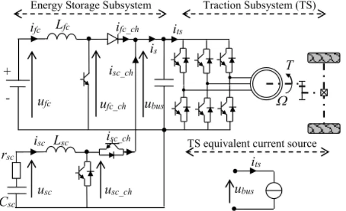
A 15 kW FC/SC vehicle is considered (Fig. 1). The Energy Storage Subsystem (ESS) is composed of the FC, the SC, their corresponding smoothing inductors and choppers and a DC bus capacitor. The FC is considered as a voltage source char-acterized by its static polarization curve, i.e. an experimentally validated static model [9]. A series R-C model is used to con-sider only the fast dynamics of the supercapacitors [17]. The equations of the ESS and vehicle model are summarized in Table 1 [16]. To deal with the Backstepping control of the coupled sources, the focus is put on the FC/SC electric parallel connection. This energetic coupling distributes the power of the FC and SC subsystems to the DC bus and to the load. The currents of the FC and SC choppers, respectively ifc_ch and
isc_ch, are added together to generate the source current is. It is
modelled by the Kirchhoff’s current law (5). The DC bus ca-pacitor then sets its voltage ubus on the system.
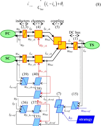
B. Energetic Macroscopic Representation
EMR is a functional description of energetic systems for control purpose [15], [18], [19]. The system is divided into basic interacting subsystems. All elements are interconnected according to the action and reaction principle using exchange variables. The product of the action and reaction variables between two elements corresponds to the instantaneous power flow. Only the integral causality is considered in EMR. This property leads to defining accumulation elements by time de-pendent relationships, in which outputs are integral functions of inputs. Other elements are described using relationships without time dependence. The EMR of the studied vehicle has been proposed in [16] (upper part in Fig. 2). The FC, the SC and the traction subsystem are considered as electrical sources (green oval pictograms, cf. appendix). The choppers perform mono-domain conversions (orange square pictograms). The
itot1 ufc ubus Lfc ifc ifc_ch ufc_ch usc Lsc isc isc_ch usc_ch T its is isc_ch + - rsc Csc
Energy Storage Subsystem Traction Subsystem (TS)
ubus its
TS equivalent current source
Fig. 1. Studied fuel cell/supercapacitors vehicle architecture TABLE 1.MATHEMATICAL MODEL OF THE STUDIED FC/SC VEHICLE
DC bus
ts s bus ts s bus C s G i i i i u 1 with s the Laplace operator (1) FC inductor
fc fc ch
fc fc ch fc fc fc u u G r s L u u i _ 2 _ ) ( (2) SC inductor
sc sc ch
sc sc ch sc sc sc u u G r s L u u i _ 3 _ ) ( (3) Choppers _ _ _ _ X ch X ch bus X ch X ch Xu
u
i
i
with X
fc,sc
and
hX ch_
0,1
(4) Coupling isifc_chisc_ch (5) Traction Subsystem
bus ed m ts u P i
(6)3
parallel connection between the FC and the SC choppers is represented by a mono-domain distribution element (overlap-ping squares). The smoothing inductors and the DC bus capac-itor are accumulation elements (orange rectangle pictograms with diagonal line). The DC bus voltage ubus, the FC current ifc and SC current isc are thus the state variables of the vehicle ESS.
C. Inversion-based control scheme
From inversion rules, EMR can define an inversion-based control scheme. This kind of control is organized in two lev-els: local and global controls. The local control level, de-scribed by light blue parallelograms in Fig. 2, controls the components of the system. The global control level, described by a dark blue parallelogram in Fig. 2, coordinates the local control to manage the whole system. The main control objec-tive is to impose the DC bus voltage ubus to the system. Two tuning variables, the duty cycles αfc_ch and αsc_ch, are used to
achieve this goal. The local control is then deduced by invert-ing the EMR from the DC bus voltage ubus to the duty cycles
αfc_ch and αsc_ch. The global control strategy block in Fig. 2, aims to manage the whole system by defining the distribution between the FC and the SC. The crossed blue parallelograms correspond to the inversion of accumulation elements using closed-loop controls. The blue parallelograms correspond to the inversion of conversion elements using open-loop control. The overlapped blue parallelograms correspond to the inver-sion of the energetic coupling of the sources.
Fig. 2 shows that 3 closed loop controllers are required to control the state variables ifc, isc and ubus. Open-loop direct inversions are needed to invert the choppers. The reference current of the coupling inversion is-ref defines two variables required by the system to control the DC bus and to manage the energy flows: the currents of the supercapacitors chopper
isc_ch and of the fuel cell chopper ifc_ch. This distribution results from the inversion of the energetic coupling between the choppers (5). The inversion of this coupling requires a second input to implement an energy distribution criterion, kD in (7).
kD is provided by an energy management strategy and it links the control scheme with the strategy block. It is the key to manage the whole system.
_
_
=
_fc ch ref D s ref sc ch ref s ref fc ch ref
i
k i
i
i
i
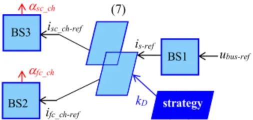
(7)D. Division of the Backstepping control
Backstepping control is composed of several recursive steps that gave the method its name [12]. The key idea is to divide the MIMO system into SISO subsystems to define a control scheme with cascaded loops. The cascade closed-loop control design is defined following Lyapunov stability condi-tions [24]. There is no dedicated procedure to design the Backstepping control for coupled systems. The inversion-based control of EMR defines a systematic control scheme and like for the Backstepping control, the inversion-based control is composed of cascaded loops. In [16] it was shown that EMR can be used to define directly the cascaded loops of Backstep-ping control. Nevertheless, the energetic coupling has not been
taken into account. Herein, the inversion-based control scheme is used to define the procedure of Backstepping control by taking into account the energetic coupling. In this way, three SISO subsystems can be considered for the Backstepping con-trol design (Fig. 3):
A) DC bus voltage loop (BS1); B) FC current loop (BS2); C) SC current loop (BS3).
The Backstepping control is then applied separately to each control part. Hence the inversion-based control structure of EMR allows dividing directly the procedure of the Back-stepping control design.
III. ADAPTIVE BACKSTEPPING CONTROL OF THE STUDIED FC/SCSYSTEM
A. DC bus voltage loop (BS1)
First, the DC bus capacitor is considered with its equation (1). The system parameters can change and disturbances act upon the system. It is then appropriate to consider unknown parameters for real-time application [22], [23]. Let us intro-duce unknown parameter θ1 into (8) to include resistance or capacitance uncertainties of the DC bus capacitor. Adaptive Backstepping control technique is then used to take uncertain-ties into account.
11
bus s ts busu
i i
C
(8) ubus its sc_ch usc_ch-ref isc-ref ufc_hc-ref ifc-ref fc_ch ifc ufc kD ubus-ref strategy is-ref isc_ch-ref ifc_ch-ref ubus ifc_ch ubus ifc FC ufc ifc ufc_ch fc_ch isc SC usc isc usc_ch ubus ubus isc_ch is TS (15) (39) (36) (35) (38) (7) (37) (40) DC bus choppers inductors coupling (2,3) (4) (5) (1) ufc4 ubus-ref BS1 BS2 BS3 strategy sc_ch fc_ch is-ref isc_ch-ref ifc_ch-ref kD (7)
Fig. 3. Division of the Backstepping control
The objective is to deduce a local control law to control the voltage ubus from the energy source current is. Error e1 is de-fined as:
1 1 1 1
ts s bus ref bus bus ref bus i i C u e u u e (9)As θ1 is unknown, its estimation and estimation error ˆ1
1
are introduced as:
1 1
1
ˆ
(10)
Here, the variations of θ1 are assumed to be slow. A control Lyapunov function (clf) V1 is proposed. It defines an image of the DC bus energy in respect with the Lyapunov-LaSalle theo-rems [25]: 1 1 1 1 1 1 1 1 1 1 1 2 1 1 ˆ 2 1 2 1
C ee V e C V bus bus (11)where Γ1 is a positive constant, which will be chosen in func-tion of the desired performances.
Using (9) and (10), introducing variable is-ref and from the assumption of slow variations of θ1, (11) results into
1 1 1 1 1 1 1 1 1 1 ˆ ˆ e C i i e C i i u C e V bus s ref s bus ts ref s ref bus bus (12) A term c1e1, with c1 ≥ 0, is introduced to impose theLya-punov stability condition V1≤ 0:
is ref is
e e c V 2 1 1 1 1 (13)The impact of the term e1 (is-ref – is) on the global system stability will be checked at the end of the Backstepping control process. A first local control law is-ref is deduced by identifica-tion of V1in (12) and (13):
1 1
1e Cbusubus ref is ref its Cbusˆ
c
(14)
1 1
1 bus bus ref ts bus
ˆ ref s ce C u i C i (15) and 1 1 1 ˆ C e bus (16) such that 0 ˆ 1 1 1 1 1 1 C e bus (17) The first local control law output is reference current is-ref(15). It is defined through a controller consisting of a control law and an update law to obtain . is-ref is an input of the next ˆ1 local control loop.
B. FC current loop (BS2)
From (2) and (4), a FC local control loop is required to control the currents ifc_ch from the boost chopper duty cycles αfc_ch (16). The unknown parameter θ2 is introduced to repre-sent inductor or source model inaccuracies. In real-time, αfc_ch varies at the rate of the sampling frequency. αfc_ch is then as-sumed constant by parts so that from (2) and (4) we obtain
2 _ _ _ _ _ 1 ch fc ch fc fc bus ch fc fc fc ch fc ch fc i r u u L i (18)
Error e2 is defined as:
2 _ _ _ _ _ 2 _ _ 2 1 ch fc ch fc fc bus ch fc fc fc ch fc ref ch fc ch fc ref ch fc i r u u L i e i i e (19)
To develop the current controller, clf V2 is defined as:
2 1 2 2 _ 2 2 _ 2 2 1 2 2 _ 2 2 _ 2 ˆ 2 1 2 1
ch fc ch fc fc ch fc ch fc fc e e L V e L V (20)where Γ2 is a positive constant, and
2 2
2
ˆ
(21)
To impose the stability condition V2 ≤ 0 with constant
c2 ≥ 0 ch fc e c V2 2 22 _ (22)
(20) and (22) are compared using (19), (20) and (21) and the assumption of slow variations of θ2, to develop the control law for αfc_ch and the associated uncertainty estimator:
2 _ _ 2 _ _ _ _ _ 2 2 ˆ fc bus ch fc fc ch fc ch fc ref ch fc fc ch fc ref ch fc fc ch fc L u u e i r i L e c (23) 2 _ 2 2 _ 2 _ _ _ _ _ ˆ / 1 fc ch fc fc ch fc ch fc ref ch fc fc ch fc ref ch fc fc bus ch fc L e c u e i r i L u (24) and ch fc fce L 2 2 _ 2 ˆ such that 0 ˆ 2 1 2 2 _ 2 2 ch fc fce L (25)
5
C. SC current loop (BS3)
The SC local control law αsc_ch is deduced in the same way as for the FC control loop. The unknown parameter θ3 is added to represent other inductor or source model inaccuracies. αsc_ch is assumed constant by parts:
3 _ _ _ _ _ 1 ch sc ch sc sc bus ch sc sc sc ch sc ch sc i r u u L i (26) 3 _ 3 3 _ 3 _ _ _ _ _ ˆ / 1 sc ch sc sc ch sc ch sc ref ch sc sc ch sc ref ch sc sc bus ch sc L e c u e i r i L u (27) and ch sc sce L 3 3 _ 3 ˆ (28)
where c3 and Γ3 are positive constants and:
ch sc ref ch sc i i e3 _ _ (29) 3 3 3
ˆ
(30)D. Stability and controller scheme analysis
The global system stability is guaranteed if the derivative of the global clf Vglobal is negative (31). Replacing is-ref using (5), (7), e2 (19) and e3 (29) in (31) leads to (32). 3 2 1 V V V Vglobal (31)
3 2 1 3 2 1 1 _ 2 3 3 _ 2 2 2 2 1 1 e e e A e e e i i e e c e c e c Vglobal fc ch sc ch s ref s with (32) ch sc ch fc c c c A _ 3 _ 2 1 0 2 1 0 2 1 2 1 2 1 (33)From (33), the derivative of Vglobal is negative if the sym-metrical matrix A is positive. Considering that αfc,sc_ch ∈ [0,1] and using the Sylvester criterion [26], A is positive and the global system is stable if the following conditions are satis-fied: 3 2 1 3 2 16 1 16 1 0 0 c c c c c (34) It should be noted that the introduction of the distribution criterion kD from (7) does not alter these conditions if kD dy-namical variations are slower than the current loop dynamics.
From (24) and (27), the tuning inputs αfc_ch and αsc_ch con-trol laws can be broken down into six parts to achieve the same form as the inversion-based control scheme (equation numbers are listed on Fig. 2):
ch fc ref ch fc ref fc i i _ _ (35) ch fc fc ch fc ref fc fc fc ref fc fc ref ch fc e c u e i r L i L u _ 2 2 _ 2 2 _ ˆ (36) bus ref ch fc ch fc_ u _ /u (37) ch sc ref ch sc ref sc i i _ _ (38) ch sc sc ch sc ref sc sc sc ref sc sc ref ch sc L i L r i e u c e u _ 3 3 _ 3 3 _ ˆ (39) bus ref ch sc ch sc_ u _ /u (40)
The control laws defined by Vglobal, (15), (36) and (39) de-fine three controller schemes, which depend on feedback con-stants ci and integral update laws ˆi with gains Γi, i={1,2,3}. These integral functions result from the disturbance estimation with the unknown parameters θ1, θ2 and θ3. The resulting closed loop controllers on Fig. 2 take the form of Proportional Integral (PI) controllers CPIi with proportional terms kpi=f(ci) and integral terms kii=f(Γi), i={1,2,3}, to ensure the robustness of the system. The control schemes deduced from adaptive Backstepping control are then depending on PI controllers and parameters of the studied system. Compensation of the dis-turbance current its and voltages ufc and usc are also used. Fi-nally anticipation terms, the inversion of the transfer functions
Gi, i={1,2,3}, act on the reference state variables ubus-ref, ifc-ref and isc-ref using derivative terms. Equations (15), (36) and (39) are then factored as follows:
1 1 1 1 bus ref ts PI ref s G u i eC i (41) with CPI kp ki /s c
Cbus2 1
/s 1 1 1 1 andG11Cbuss
fc ref PI fc ch
fc ref ch fc u G i eC u _ 21 2 2 _ (42) with CPI kp ki /s c rfc
L2fc 2/s 2 2 2 2 and G21Lfcsrfc
sc ref PI sc ch
sc ref ch sc u G i eC u _ 31 3 3 _ (43) with CPI kp ki /s c rsc
L2sc 3/s 3 3 3 3 and G31Lscsrsc IV. REAL-TIME VALIDATIONA. Experimental setup
The simulation of the Backstepping control of the studied FC/SC vehicle has been carried out in [16]. Nevertheless, sim-ulation studies are limited by modelling assumptions. Based on the traction characteristics of the Tazzari Zero battery elec-tric vehicle [27], a reduced scale validation is proposed on an experimental platform (Fig. 4). It is composed of a 1.2 kW Ballard FC, a bank of Maxwell SC, two smoothing inductors, two choppers, and a controlled current source to emulate the traction subsystem (Fig. 1). The controlled current source is then chosen as a load drive with a ratio current reduction of 40
6
compared to the full-scale studied vehicle (Table 2). Voltages and currents are measured with classical LEM transducers. No additional numerical filters have been added.
B. Energy management strategy
A filtering strategy is considered for the FC/SC power dis-tribution to avoid fast FC power dynamics, which are limited by the FC air compressor supply. This kind of strategy is often used due to its simplicity and robustness for real-time imple-mentation [28]. The FC power must be positive with a fre-quency below 100 mHz to reduce stack faults and degradations [29]. The SC then provides the resulting transient power. Herein, a low-pass filter with cut-off frequency fc=15 mHz is used for the distribution parameter kD:
s f f k c c D2
2 (44) As a consequence, kD has slow dynamics compare to the internal current loop, which satisfies stability conditions. FromkD and (7), the low-frequency source current part is provided by the FC and the high-frequency source current part by the SC (45). In addition, the distribution criterion is augmented to include a saturation function to impose ifc_ch > 0. This
guaran-tees to have an exclusively positive power for the fuel cell. It may be noted that more advanced distribution strategies based on optimization methods could be proposed by changing the value of kD [17]. ref ch fc ref s ref ch sc ref s c c ref s c c ref s c c ref s c c ref ch fc i i i i s f f i s f f i s f f i s f f sat i _ _ _ 0 2 2 if 2 2 0 2 2 if 0 2 2
(45)C. Results and Discussion
The developed Backstepping control scheme, the energy management strategy and the traction emulation are imple-mented in a dSPACE 1103 controller board using MATLAB-SimulinkTM. The sampling period is set to tsamp=200 μs. It should be noted that the synchronized sampling naturally fil-ters the discontinuous values of the traction system current its. A standard driving cycle for light vehicles homologation, WLTC, for a class 2 vehicle is first considered (Fig. 5a). The controller parameters ci andΓi, i={1,2,3}, are identified based on pole placement controller tuning design [30]. The roots of the second order characteristic equation of each control loop characterize the error dynamics transients, i.e. their poles. The poles are placed according to the desired response time.
The driving cycle imposes a traction current its in function of the emulated vehicle characteristics and control (Fig. 6a). By the use of the distribution criterion kD, the chosen filtering strategy leads to use the SC for fast and regenerative braking power transients while the FC handles low frequencies posi-tive powers (Fig. 6b). All the powers, currents and voltages are plotted in per-unit.
1.2 kW Fuel Cell dSPACE 1103 Power electronic Smoothing inductor SC H2 canister
Fig. 4. Experimental platform TABLE 2.STUDIED FC/SC VEHICLE PARAMETERS
Full-scale FC/SC EV Fuel Cell 55-78 V / 20 kW Supercapacitors 54 V, 130 F Smoothing inductors 0.25 mH / 5.5 mΩ DC bus capacitor 80 V / 53 mF Electric drive 15 kW Vehicle 811 kg FeedBack constants c1 = 0.26, c2 = c3 = 1.6 Adaptation gains Γ Γ1 = 1.6 104, 2 = Γ3 = 8.04 108 vehicle speed vev (km/h) time (s) (a) (b) (c)
Fig. 5. Considered driving cycles
(a) WLTC of class 2, (b) acceleration test, (c) real driving cycle The DC bus power (Pbus=ubus·is) is then compensated by both sources and reaches a maximum of 1 pu in traction and a minimum of -0.35 pu in braking phase. The FC and SC volt-ages depend on their corresponding currents (Fig. 6c). It should be noted that the initial SC voltage usc at t=0 s is equal to 0.5 pu. The final voltage usc at t=1,500 s has the same value. The energy balance of the filtering strategy is zero because the electrical losses are negligible within the experimental period of 1,500 s.
The developed Backstepping control manages the coupling to maintain the DC bus voltage to 80 V=1 pu (Fig. 7a). The DC bus voltage variation is ± 5%. The voltage drops are neg-ligible with respect to the electric drive supply. At all time, the FC and the SC currents are well managed because they track their references delivered by the traction requirement (Fig. 7a
7
b and c). Experimental results demonstrate that the
Backstep-ping control of the energetic coupling is implementable in real-time conditions. As expected, the real-time conditions do not affect the stability of the controlled system due to the real-time disturbance estimation and update into the controllers. In this way, the supercapacitors can help the fuel cell to meet the requirements of the load with a guarantee of system stability in real-time.
A comparison with classical PI controllers is proposed to show the improvement in term of transient behaviour. Fig. 8 compares the experimental control performance of the DC bus voltage ubus, for the PI and backstepping based controllers and three driving cycles: WLTC, an acceleration test and an urban driving cycle from an on-road test realized around the Univer-sity of Lille 1 (Fig. 5). The voltage tracking performances are close. However, the PI control (red curves) shows greater voltage oscillations, particularly when the power flow dynam-ics are important (purple framed areas in Fig. 8). Here, the emulated system has been properly designed. The control loops also respects the system time constants because an ex-pertise of the system has been developed during this work. It is therefore logical, and even preferable, that both Backstepping and PI controllers have similar overall performances.
V. CONCLUSION
This paper deals with a stable control for a fuel cell vehicle using supercapacitors with a Backstepping control technique for real-time implementation. EMR has been used to organize the Backstepping control scheme in a clear way for this cou-pled system. In this way, three Backstepping cascaded control loops, coupled by a distribution criterion, have been devised. Each Backstepping control loop has been designed to impose a local stable behavior. Moreover the global stability of the whole system has also been demonstrated. The developed Backstepping control has been validated in real-time on an experimental setup. Experimental results have shown that the supercapacitors can help the fuel cell to meet the power re-quirements with a guarantee of system stability for the cascad-ed loops. Moreover, if the same architecture is kept, the de-picted method can be used for other hybrid vehicle as a fuel cell/battery vehicle without any additional consideration. As indicated in [31], the control organization of a battery / super-capacitor system could be the same. For the future, more ad-vanced strategies could be used for the same control organiza-tion. Backstepping control laws include derivative operations that could be sensitive to large step reference variations. Addi-tional work is required to manage saturation effects at the con-trol law development stage.
time (s) (a) (b) voltage ufc and usc (pu) (c) power (pu)
traction system current its (pu)
ufc usc Pfc Psc Pbus
Fig. 6. Global experimental results for the WLTC driving cycle: traction cur-rent load, power distribution and fuel cell and supercapacitor voltages
time (s) voltage ubus (pu) ubus-ref
ubus-mea (a) current ifc (pu) (b) current isc (pu) (c) ifc-ref ifc-mea isc-ref isc-mea
Fig. 7. State variables control for the WLTC driving cycle: DC bus voltage, fuel cell and supercapacitor currents
voltage ubus (V) reference Back. time (s) (a) (c) (b) PI
Fig. 8. DC bus voltage ubus for PI and backstepping
based controllers for three driving cycles.
REFERENCES
[1] A. Veziroglu, and R. Macario, “Fuel cell vehicles: State of the art with economic and environmental concern”, International Journal of
Hydro-gen Energy, vol. 36, no. 1, pp. 25–43, Jan. 2011.
[2] A. Khaligh and L. Zhihao, “Battery, ultracapacitor, fuel cell, and hybrid energy storage systems for electric, hybrid electric, fuel cell, and plug-in hybrid electric vehicles: State of the art”, IEEE Trans. Veh. Technol., vol. 59, no. 6, pp. 2806–2814, Jul. 2010.
[3] R. Álvarez-Fernández, F. Beltrán Cilleruelo, and I. Villar Martinez, “A new approach to battery powered electric vehicles: A hydrogen fuel-cell range extender system”, International Journal of Hydrogen Energy, vol. 41, no. 8, pp. 4808-4819, Mar. 2016.
[4] A. Payman, S. Pierfederici, F. Meibody-Tabar, and B. Davat, “An adapted control strategy to minimize DC-bus capacitors of a parallel fuel cell/ultracapacitor hybrid system”, IEEE Trans. Power Ele., vol. 26, no. 12, pp. 3843–3852, Aug. 2009.
[5] Honda, Honda Fuel Cell Power – FCX. Press Release, available on the world wild web at: http://world.honda.com/FuelCell/ FuelCellVehicle-history/FCX-2002/index.html, date accessed: March 2017.
[6] H. Aouzellag, K. Ghedamsi, and D. Aouzellag, “Energy management and fault tolerant control strategies for fuel cell/ultra-capacitor hybrid electric vehicles to enhance autonomy, efficiency and life time of the fuel cell system”, International Journal of Hydrogen Energy, vol. 40, no. 22, pp. 7204‑7213, Jun. 2015.
[7] H. Hemi, J. Ghouili, and A. Cheriti, “Combination of Markov chain and optimal control solved by Pontryagin’s minimum principle for a fuel cell/supercapacitor vehicle”, Energy Conversion and Management, vol. 91, pp. 387‑393, Dec. 2015.
[8] P. Thounthong, L. Piegari, S. Pierfederici, and B. Davat, “Nonlinear intelligent DC grid stabilization for fuel cell vehicle applications with a supercapacitor storage device”, International Journal of Electrical
Pow-er & EnPow-ergy Systems, vol. 64, pp. 723‑733, Jan. 2015.
[9] J. Jia, Q. Li, Y. Wang, Y. T. Cham, and M. Han, “Modeling and dynam-ic characteristdynam-ic simulation of a proton exchange membrane fuel cell,”
IEEE Trans. Ener. Conv., vol. 24, no. 1, pp. 283–291, Jan. 2009.
[10] H. El Fadil, F. Giri, J.M. Guerrero, and A. Tahri, “Modeling and nonlin-ear control of a fuel cell/supercapacitor hybrid energy storage system for electric vehicles”, IEEE Trans. on Vehicular Technology, vol. 63, no. 7, pp. 3011-3018, Sep. 2014.
[11] M. Rajabzadeh, S. Mohammad Taghi Bathaee, and M. Aliakbar Golkar, “Dynamic modeling and nonlinear control of fuel cell vehicles with dif-ferents hybrid power sources”, International Journal of Hydrogen
Ener-gy, vol. 41, no. 30, pp. 3185-3198, Jan. 2016.
[12] J. Zhou, and C. Wen, “Backstepping control”, in Control and
Mecha-tronics, CRC Press, pp. 20–1 – 20–22, ISBN 9781439802878, Feb.
2011.
[13] W. Dong, J. A. Farrell, M.M. Polycarpou, and V. Djapic, “Command filtered adaptive backstepping”, IEEE Trans. Control Syst. Technol., vol. 20, no. 3, pp. 566–580, Mar. 2011.
[14] O. Herizi, and S. Barkat, “Backstepping control and energy management of hybrid DC source based electric vehicle”, EFEA 2016, Belgrade, Ser-bia, Sept. 2016.
[15] C. Dépature, P. Sicard, A. Bouscayrol, W. Lhomme, and L. Boulon, “Comparison of Backstepping control and Inversion Based Control of a range extender electric vehicle”, IEEE VPPC’14, Coimbra, Portugal, Oct. 2014.A. Bouscayrol, J.P. Hautier, and B. Lemaire-Semail, “Graphic
formalisms for the control of multi-physical energetic systems: COG and EMR”, Systemic Design Methodologies for Electrical Energy Systems, Chap. 3, Wiley-ISTE, ISBN 9781848213883,Oct. 2012.
[16] C. Dépature, W. Lhomme, P. Sicard, A. Bouscayrol, and L. Boulon, “Backstepping control of a fuel cell/supercapacitor system for electric vehicle”, IEEE VPPC’16, Hangzhou, China, Oct. 2016.
[17] L. Zubieta, and R. Bonert, “Characterization of double-layer capacitors for power electronics application”, IEEE Trans. Ind. App., vol. 36, no. 1, pp. 199-205, Feb. 2000.
[18] A.L. Allègre, A. Bouscayrol, and R. Trigui, “Flexible real-time control of a hybrid energy storage system for electric vehicles”, IET Electrical
Systems in Transportation, vol. 3, no. 3, pp. 79-85, Mar. 2013.
[19] J. Solano Martinez, D. Hissel, M.C. Pera, and M. Amiet, “Practical control structure and energy management of a testbed hybrid electric ve-hicle”, IEEE Trans. on Vehicular Technology, vol. 60, no. 9, pp. 4139-4152, Sep. 2011.
[20] W. Lhomme, P. Delarue, A. Bouscayrol, P. Lemoigne, P. Barrade, A. Rufer, “Comparison of control strategies for maximizing energy in a su-percapacitor storage subsystem”, EPE Journal, vol. 19, no. 3, pp. 5-14, Sep. 2009.
[21] C. M. Lee, S. H. Han, C. H. Zheng, and L. We-Song, “Power split of fuel cell/ultracapacitor hybrid power system by backstepping sliding mode control”, 10th Int. Power & Energy Conference (IPEC), Ho Chi Minh City, Vietnam, Dec. 2012.
[22] C. Kaddissi, J. P. Kenné, and M. Saad, “Indirect adaptive control of an electrohydraulic servo system based on nonlinear Backstepping”, IEEE
Trans. Mechatron., vol. 16, no. 6, pp. 1171‑1177, Dec. 2011.
[23] W. S. Black, P. Haghi, and K. B. Ariyur, “Adaptive systems: History, techniques, problems, and perspectives”, systems, vol. 2, pp. 606-660, 2014.
[24] P.V. Kokotovic, “The joy of feedback: Non linear and adaptive,” IEEE
Trans. Control Syst., vol. 12, no. 3, pp. 7–17, Jun. 1992.
[25] H.K. Khalil, “Nonlinear systems”, New Jersey : Prentice Hall, Chapter “Lyapunov Stability”, pp. 111 – 194, ISBN 978-0130673893, 2001. [26] R. A. Horn, and C. R. Johnson, “Matrix Analysis”, Chapter 7: Positive
Definite and Semidefinite Matrice, Cambridge University Press, ISBN 978-0-521-83940-2, 2013.
[27] Tazzari zero website’, http://www.tazzari-zero.com/, accessed February 06th 2016
[28] T. Azib, O. Bethoux, G. Remy, and C. Marchand, “Saturation manage-ment of a controlled fuel-cell/ultracapacitor Hybrid Vehicle”, IEEE
Trans. on Vehicular Technology, vol. 60, no. 9, pp. 4127-4138, Nov.
2011.
[29] V. Liso, M. Pagh Nielsen, and S. Knudsen Koer, “Thermal modeling and temperature control of a PEM fuel cell system for forklift applica-tion”, International Journal of Hydrogen Energy, vol. 39, pp. 8410-8420, Apr. 2014.
[30] K. Ogata, “Design of Control Systems in State Space”, in Modern
Con-trol Engineering, Fourth Edition, Prentice Hall, pp. 826-951, ISBN
0-13-060907-2, USA, 2002.
[31] A. Castaings, W. Lhomme, R. Trigui, A. Bouscayrol,, "Real-time energy management strategies of a battery/supercapacitors system for Electric Vehicle under limitations”, Applied Energy, Vol. 163, February 2016, pp.190–200
APPENDIX: EMR PICTOGRAMS
Energy accumulation
(ex. inductor) Closed-loop control
Source
name Energy source (ex. fuel cell)
Mono-domain converter (ex. chopper)
Open-loop control Sensor
Energy distribution (mono-domain)
Coupling inversion with distribution
9
Clément Dépature received his master’s degree in Electrical Engineering from the Université Lille1 (France) in 2011. In 2011, he worked as an engineer at L2EP, in Lille. He was in charge of the development of an experimental platform dedicated to electric and hybrid vehicles and of the Tazzari Zero monitoring.
He obtained a Ph.D in collaboration with the L2EP and the GREI (Groupe de Recherche en électronique Industrielle) of the Université du Québec à Trois-Rivières (Canada) in 2017. Since 2017, he holds a postdoctoral position at the Hydrogen Research Institute. His research activities deal with modeling, linear and non-linear control and energy management for fuel cell, hybrid and electric vehicles.
Walter Lhomme (M’16) received the M.S. degree in 2004, and the Ph.D. degree in 2007, both in electrical engineering, from the University Lille 1, Sciences and Technologies, Villeneuve d’Ascq, France, specializing on graphical description tools and methods for modeling and control of electrical systems.
He worked as hybrid electric vehicle engineer within the Department Controls, Hybrid Vehicle Technologies Team at AVL Powertrain UK Ltd., England, for 1 year. Since September 2008 he has been engaged as Associate Profes-sor at the Laboratory of Electrical Engineering and Power Electronics of Lille (L2EP), University Lille 1. Since 2008, he is the responsible of the experimental platform “electrici-ty & Vehicle” of the L2EP at the Universi“electrici-ty Lille 1. His research activities deal with the graphical descriptions, modelling, control, energy management and hardware-in-the-loop simulations applied in hybrid and electric vehicles field.
Pierre Sicard (S’84–M’85) received the M.S. degree in industrial electronics from the University du Québec à Trois-Rivières, Trois-Rivières QC, Canada, in 1990, and the Ph.D. degree in electrical engineering from Rensselaer Polytechnic Institute, Troy NY, in 1993.
He joined the Université du Québec à Trois-Rivières in 1992 where he has been Professor in Electrical and Com-puter Engineering since 2001. He held the Hydro-Québec Research Chair on Power and Electrical Energy from 1999 to 2003 and he was Director of the Research Group on In-dustrial Electronics from 2004 to 2011. His current research interests include modeling, controller and observer design for nonlinear systems, including motor drive control, con-trol of electromechanical systems, multi-drive systems, load sharing control problems, control in power electronics, adaptive control, and artificial intelligence.
Alain Bouscayrol (M’02) received a Ph.D. degree in Electrical Engineering from the Institut National Polytechnique de Tou-louse, France, in 1995.
From 1996 to 2005, he was Associate Professor at University Lille1, France, where he has been a Professor since 2005. Since 2004, he has managed the national network on Ener-gy Management of Hybrid Electric Vehicles France. He has initiated the Energetic Macroscopic Representation (EMR) in 2000 for the description and the control of energetic sys-tems. His research interests at the L2EP include graphical descriptions for control of electric drives, wind energy con-version systems, railway traction systems, hybrid electric vehicles and hardware-in-the-loop simulation.
Loïc Boulon (M'10, SM'16) received the master degree in electrical and automatic control engineering from the University of Lille (France), in 2006. Then, he obtained a PhD in electrical engineering from Univer-sity of Franche-Comté (France). Since 2010, he is a professor at Université du Québec à Trois-Rivières (Canada) and he works at the Hy-drogen Research Institute (Full Professor since 2016). His work deals with modeling, control and energy management of multiphysics systems. His research interests include hy-brid electric vehicles, energy and power sources (especially battery in cold weather operation), and fuel cell systems. He has published more than 100 scientific papers in peer-reviewed international journals and international confer-ences.
In 2015, Loïc Boulon was general chair of the IEEE-Vehicular Power and Propulsion Conference in Montréal (QC, Canada). Prof. Loïc Boulon is VP-Motor Vehicles of the IEEE Vehicular Technology Society and he is the hold-er of the Canada Research Chair in Enhold-ergy Sources for the Vehicles of the future.