A Design Tool for Reusing Integration Knowledge
in Simulation Models
MASSACHUSETTrS INSTITU1TE OF TECHNOLOGY by
Sangmok Han
JUL 2
9
2011
B.S. Mechanical Engineering
LIBRAR
IES
Seoul National University, 2000
SUBMITTED TO THE DEPARTMENT OF MECHANICAL ENGINEERING IN PARTIAL FULFILLMENT OF THE REQUIREMENTS FOR THE DEGREE OF
MASTER OF SCIENCE IN MECHANICAL ENGINEERING AT THE
MASSACHUSETTS INSTITUTE OF TECHNOLOGY JUNE 2006
© 2006 Massachusetts Institute of Technology. All rights reserved. The author hereby grants to MIT permission to reproduce
and to distribute publicly paper and electronic copies of this thesis document in whole or in part
in any medium now known or hereafter created/
Signature of Author ... ... .... ... .L / . ...
Department of Mechanical Engineering -May 12,0 C ertified by. .. .. .. .. .. .. .. .. . .. ... ....
David Wallace
Esther and Harold E. erton Associate Professor
- Thesis Swervisor
Accepted by... ... ...
Lallit Anand Chairman, Department Comnmittee on Graduate Students
A Design Tool for Reusing Integration Knowledge
in Simulation Models
By
Sangmok Han
Submitted to the Department of Mechanical Engineering
on 12 May 2004, in partial fulfillment of the requirements
for the degree of Master of Science in Mechanical Engineering
A
bst
ract
In the academic field of computer-aided product development, the role of the design tool is to
support engineering designers to develop and integrate simulation models. Used to save time
and costs in product development process, the simulation model, however, introduces
additional costs for its development and integration, which often become considerably large
due to the fact that many, complex simulation models need to be integrated. Moreover, the
result of integration and the effort taken during the integration process are often not reused
for other product development projects. In this paper, we attempt to develop a design tool that
can capture integration knowledge and make the knowledge reusable for other design tasks.
More specifically, we are interested in the two kinds of integration knowledge: the first
captured in the form of a graph structure associating simulation models, called the integration
structure, and the second generalized from script codes into rule-based patterns, called the
integration code pattern. An integration mechanism and a pattern generalization algorithm
have been developed and incorporated into a design tool utilizing a new integration model
called
catalog model,
a model that enables us to reuse the integration structure and code
patterns of one model to quickly build another. Application scenarios have demonstrated the
effectiveness of the design tool: The same integration task could be performed in less time,
and repetitive and error-prone elements in the task were substantially reduced as a result of
reusing integration knowledge in the simulation models.
Thesis Supervisor: David Wallace
Contents
Contents ...
3
List of Figures ...
... .5
Chapter 1 Introduction...
7
1.1. M otivation ... 7
1.2. Concepts and Terminology ... 9
1.3. Goal ... ... 10
1.4. Contributions ... 12
1.5. Overview ... 13
Chapter 2 Reuse Scenarios ...
14
2.1. Reuse of the Integration Structure ... 14
2.1.1. Scenario terminology ... 14
2.1.2. Scenario of reusing the integration structure... 15
2.2. Reuse of the Integration Code Pattern ... 20
2.2.1. Exemplary reuse problems ... 20
2.2.2. Scenario of reusing the integration code pattern ... 23
Chapter 3 Related Work...25
3.1. Approaches ... 25
3.1.1. Software engineering approach to reusability ... 25
3.1.2. Source code mining approach to reusability ... 26
3.1.3. User interface design approach to reusability... 28
3.2. Challenges ... 28
Chapter 4 Im plem entation...
.33
4.1. System Overview... 33
4.1.1. Functional requirements ... 33
4.1.2. Design parameters ... 34
4.1.3. Component map ... 37
4.2. Catalog M odel Definition... 39
4.2.2. A ddressing m echanism ... 41
4.3. D ependency Solving Algorithm ... 42
4.3.1. Overview of the algorithm ... 43
4.3.2. Pseudo code... 44
4.4. Pattern Generalization Algorithm ... 46
4.4.1. Overview of the algorithm ... 46
4.4.2. A lgorithm term inology... 48
4.4.3. Pseudo code... 49
4.5. Catalog M odel Builder ... 56
4.5.1. Layout of the catalog model builder... 56
4.5.2. M odel representation... 59
4.5.3. D ependency visualization... 61
4.5.4. Reference-by-click ... 62
4.5.5. Color-coding... 64
4.5.6. Code com pletion popup... 65
pter 5 E valuation ...
68
5.1. D oor Seal Catalog M odel ... 68
5.1.1. Evaluation goal... 68
5.1.2. Configuration of the door seal catalog m odel ... 68
5.1.3. Evaluation result... 71
5.2. Power W indow System Template ... 72
5.2.1. Evaluation goal... 72
5.2.2. Configuration of the power window system template... 73
5.2.3. Evaluation result... 76
5.3. Simulation models with Different Levels of Fidelity ... 79
5.3.1. Evaluation goal... 79
5.3.2. Configuration of the seal FEA m odel... 79
5.3.3. Evaluation result... 82
pter 6 C onclusion...
84
6.1. Sum m ary... 84 6.2. Future W ork... 85rence ...
88
Cha
Cha
Refe
List of Figures
Figure 2-1: Simulation models for a power window system... 15
Figure 2-2: Comparison between two motor simulation models ... 16
Figure 2-3: Adding a new implementation to motor simulation model ... 17
Figure 2-4: Implementation can be switched to another in run-mode... 18
Figure 2-5: By changing the implementation switch, the configuration of the power window system can be changed from using the current motor simulation model to using the new motor simulation m odel... 18
Figure 2-6: Using mapping with transformation to handling differences in interface definition... 19
Figure 2-7: The first example of code pattern generalization problem... 20
Figure 2-8: The second example of code pattern generalization problem ... 21
Figure 2-9: The third example of code pattern generalization problem... 21
Figure 2-10: The fourth example of code pattern generalization problem... 22
Figure 2-11: Reusing integration code pattern: after activating code completion... 24
Figure 4-1: Function requirements identified for the design tool... 34
Figure 4-2: Design parameters identified for the design tool... 35
Figure 4-3: Design matrix showing FRs-DPs relationship of our new design tool ... 36
Figure 4-4: A component map showing interactions among software components in the build-mode ... 38... 38
Figure 4-5: A component map showing interactions among software components in the run-mode 39 Figure 4-6: One-to-many relationship between the interface and the implementations... 41
Figure 4-7: An example of the code token matrix... 49
Figure 4-8: Code token matrix for the second row ... 51
Figure 4-9: The same number rule (SN) is assigned to column 10 and 17, denoted by yellow. The same string rule (SS) is assigned to column 1, 5, and 12, denoted by blue... 51
Figure 4-10: The gapped number rule (GN) is assigned to column 3, 7 and 14, denoted by green.. 52
Figure 4-11: The repeated string rule (RS) is assigned to column 1, 5 and 12, denoted by orange.. 52
Figure 4-12: Rule set merging of $compared-ruleset and $accepted-ruleset... 54
Figure 4-13: Catalog model editor layout ... 57
Figure 4-15: Remote relation subscription dialog layout... 59
Figure 4-16: Graphical representation of parameters and relations in the model editor ... 60
Figure 4-17: Graphical representation of the model interface in the model builder ... 61
Figure 4-18: Dependency visualization with colors: Parameters affected by the edited parameter turn gray, indicating that they are not valid targets of reference-by-click... 61
Figure 4-19: Matrix-based dependency visualization: efficient for editing, but not so for mapping 62 Figure 4-20: A click on parameter name allows user to insert a reference string to the parameter... 63
Figure 4-21: Color-coding helps detecting typing errors ... 64
Figure 4-22: Color-coding helps ease visual search of source parameters... 65
Figure 4-23: User can narrow down the code completion candidates by typing more literals. ... 66
Figure 4-24: Code completion popup supporting three modes of activation ... 67
Figure 5-1: Two door seal designs modeled in CATIA ... 69
Figure 5-2: A web page developed for executing the door seal catalog model... 71
Figure 5-3: The door seal catalog model opened in a DOME browser ... 72
Figure 5-4: Data flow among simulation models... 74
Figure 5-5: Three catalog models are added to a DOME integration project as available resources 76 Figure 5-6: The power window system template demonstrating integration structure reuse: catalog models can switch their implementations without having to change the integration structure ... 78
Figure 5-7: The seal FEA catalog allows switching between simulation models having different levels of fidelity. While the higher fidelity seal FEA model takes 4 minutes for one execution, the lower fidelity one takes less than 1 second. ... 81
Chapter 1 Introduction
1.1.
Motivation
As foreseen by social scientists, both aging population and unemployment are likely to be growing sources of social problems in many countries. Interestingly, technological development and free-market competition are causal forces that lead to improvement in quality of life while simultaneously giving rise to an aging population and reduced labor needs. Even though no one yet has come up with a clear solution for this dilemma, it can be generally agreed upon that we need to develop more job opportunities that create greater value by taking advantage of exclusively human capabilities, which are not subject to replacement by automation.
Design, be it of software, machines, or organizations, is one of the novel tasks that rely heavily on human creativity and experience, so I conjecture that designers and inventors will be increasingly important in the future. However, design is often thought to be a task best suited to talented, younger people - yet future design problems are likely to become increasingly complex, combining diversified customer needs, converging product functionalities, and rising environmental concerns. A challenging mission for design tool technologies of the future will be to allow a wider range of designers to creatively tackle increasingly complex design problems.
To address this challenge, I believe that a high priority should be placed on advancing two key functional attributes of design tools: flexibility and usability. Both functionalities aim at efficiently creating complex models, but take different approaches. The role of flexibility is to make a design tool manage changes in requirements and configurations of simulation models efficiently. The more flexible a tool is, the more complex problems designers can tackle, without being
overwhelmed by redundant, repetitive tasks introduced by design requirement changes or design exploration for a better product configuration. Meanwhile, usability seeks for compatibility with the human cognitive system. Based on the assumption that the interaction between a computer and a human is most efficient when the computer has an interface compatible with the underlying mechanism of the brain and thereby can utilize most capabilities of the brain, the role of usability is to deliver complex information in an easily digestible form, preferably customized for each designer. That way, the thought processes of designers will not distracted by procedural, tool-operation issues. In this thesis, we are interested in design tools whose role in the product development process is to help engineering designers develop and integrate simulation models. While most design tools have competent at creating simulation models, few tools address the issue of integration effectively because they does not provide an adequate level of flexibility to meet variability in modern product development process. Once a simulation model is made from several simulation model components, the components are tied to each other and cannot flexibly adapt to subsequence modification, which is often required to reflect customer requirement changes or to explore alternative design options like purchasing a standardized machine part from different vendors. Such a modification often result in budget overruns or schedule delays because a change in one simulation model has far-reaching effects on other models and making them all consistent requires considerable amount time and effort. Moreover, it is a tedious task requiring no creative thinking and thus avoided by most designers.
A usable design tool supporting the reuse of integration knowledge in simulation models is
promising solution to the current problem. We assume that the problem, the lack of flexibility in simulation models, originates from the missing support of design tools. Because current design tools do not allow designers to reuse integration knowledge in previously built simulation models, much of integration effort taken for one simulation model needs to be repeated when some
components need to be replaced or modified. We hope a design tool to be able to capture the integration knowledge in simulation models in a reusable form, so that it can be applied for building another integration model. Because time and cost wasted in redundant, repetitive tasks can be greatly saved, the product development process can employ more design iterations as well as extensive exploration of design alternatives. Reusing integration knowledge in simulation models also improves the usability of the design tool because it can provide valuable information that can save typing and prevent mistakes when combined with appropriate visualization and interaction techniques. Consequently, this thesis aims at developing mechanism, algorithm, and user interface for a design tool that enables us to capture integration knowledge in simulation models for another use.
1.2.
Concepts and Terminology
Before we begin our discussion, this section is to establish a common ground on terminology. Some terms used to describe our goal and contributions need to be defined in a narrower sense than their general use because they can have various meanings. They include simulation model, integration model, integration knowledge, relation and mapping.
Simulation model refers to a computer program that attempts to simulate behaviors of a
particular system. All simulation models in our discussion are assumed to be parametric models and therefore their behaviors are exhibited through output parameters whose values are determined by submitted values of input parameters. When the behavior of a simulation model is implemented by subscribed behaviors of other simulation models, we call the implemented simulation model as the
integration model.
As the title of the thesis - reusing integration knowledge in simulation knowledge
can be reused for building another. Integration knowledge is defined as information extracted from data in an integration model, where the information is assumed to reflect knowledge used by human during the integration process. In other word, we define integration knowledge as tangible information such as data structures or patterns that can be extracted from the model data. It is a practical definition because such tangible information not only serves sufficiently to solve reuse problems of our interest but it also eliminates the need for solving unnecessarily complicated problems of representing knowledge in a computer understandable way.
Relation is a modeling element of the simulation model to define how input parameters are
transformed to output parameters. We have two kinds of relation: local relation and remote relation. The local relation is a relation which includes script code, called relation script, and transforms parameters using the script code. The remote relation is a relation whose transformation is defined
by subscription of a model interface. Model interface is a port, represented by a set of input and
output parameters, through which a simulation model interacts with other modeling elements. When a simulation model is executed, values submitted to the input parameters are transformed into those of the output parameters.
Mapping is another modeling element of the simulation model to describing how a
parameter in one relation, called mapping target parameter, is related to parameters in other relations, called mapping source parameters. Script code called mapping script is used to define transformation between the mapping target parameter and the mapping source parameters. The mapping script is different from the relation script in the local relation in that it is a line of script code whose evaluation result is assigned to the mapping target parameter.
The goal of our new design tool is to reuse two kinds of integration knowledge:
integration structure and integration code pattern.
The integration structure is a graph structure in the integration model describing how parameters are mapped to each other. The graph structure is used to coordinate local and remote relations so that output parameters in the model interface of the integration model give the intended transformation of input parameters in the model interface. We suppose that the graph structure reflects a designer's knowledge on how to organize a given set of local and remote relations to achieve the intended transformation between input and output parameters in the model interface. It is because we expect the designer to apply the same knowledge when he or she is asked to integrate a similar set of local and remote relations, which have the same interface as the previous set but exhibit different behaviors. Therefore, the integration structure is considered as integration knowledge: its graph structure is extracted from modeling data, and the structure reflects a designer's knowledge used in the integration process.
Integration code pattern refers to a pattern generalized from mapping scripts, which is represented as a set of rules describing regularity found in the scripts. We assume that the regularity results from applying the same knowledge on naming and indexing convention over several mapping scripts; thus the set of rules is considered to reflect a designer's knowledge used in the integration process. For example, in a situation in which an engineering designer has a set of parameters that needs a similar mapping such as free-voltage mapped to freeVolt, and
stallvoltagemapped to stallVolt, we assume that the person will perform those mappings thinking
they have a consistent pattern among parameter names. As a result, when the person is asked to create another mapping for average_voltage, the answer averageVolt can be created by re-applying his or her knowledge on the regular naming pattern, which is often called naming convention.
knowledge are reused in the simulation building process, highlighting the benefit from reusing them.
1.4.
Contributions
We categorize contributions of our research in two areas: intellectual and implementational contributions. Intellectual contributions include new ideas and algorithms, while implementational contributions include mechanisms and designs, which have been adapted from other disciplines to serve our needs.
* Intellectual contribution
0 Identification of two reusable integration knowledge: Integration structure and integration code pattern
L Dependency solving algorithm: The algorithm generates an execution sequence of relations and mappings: The algorithm works with a new set of relational operators: the relation and the mapping with transformation.
l Pattern generalization algorithm: The algorithm identifies reusable integration code patterns and generalizes the patterns into a rule set
* Implementational contribution
L Implementation dispatch mechanism for the catalog model: This mechanism is used to decouple implementation from interface and to dynamically associate them in the run-mode. Conceptually, it is similar to a mechanism used for implementing polymorphism in object-oriented languages. While the object-oriented languages use a dispatch table approach, our mechanism uses a script generation approach.
0 User interface design for the catalog model builder: The graphical user interface of our design tool is specialized in reusing integration knowledge in simulation models. It utilizes techniques developed in the user interface design discipline to provide an
effective user interface.
1.5. Overview
Chapter 2 describes how our design tool achieves two goals of reusing integration knowledge. In the first scenario, the integration structure is reused to explore alternative design options. The scenario is based on an integration model for estimating the performance of power window system. The second scenario describes what kinds of integration code patterns can be captured and how we can reuse them to save integration efforts.
Chapter 3 reviews research efforts taken in other engineering disciplines to find useful concepts and techniques that can be employed to achieve our goal of reusing integration knowledge. We investigate research works done in the areas of software engineering, source code mining, and user interface design.
Chapter 4 describes how we build our design tool that can reuse two kinds of integration knowledge. The first section of the chapter provides an overview of software components in the design tool, and the proceeding sections give details on the four major software components: catalog model definition, dependency solving algorithm, pattern generalization algorithm, and catalog model builder.
Chapter 5 describes several integration scenarios, through which we validate the effectiveness of reuse features of our design tool. The integration scenarios include the door seal catalog browser, the evaluation of a power window system with various configurations, and the finite element analysis (FEA) of the door seal with multiple levels of fidelity.
Chapter 6 presents a concluding remark of this thesis. Future directions of research are discussed.
Chapter 2 Reuse Scenarios
The use case scenarios in this chapter illustrate how our design tool achieves two goals of reusing integration knowledge. The first scenario demonstrates how the integration structure is reused in a step-by-step way. The second scenario presents several integration codes containing exemplary textual patterns and shows how they can be reused.
2.1.
Reuse of the Integration Structure
2.1.1. Scenario terminology
In this section, we introduce several new terms that will be used in the integration structure reuse scenario as follows: implementation, implementation switch, mapping with transformation,
run-mode, and build-mode. The implementation refers to a collection of parameters, relations, and
mappings, which are coordinated to realize a specific behavior of a simulation model. In a new integration model supporting the reuse of integration structures, a model can have multiple implementations for one model interface. The implementation switch is a parameter placed in an integration model that diverts the source of model behaviors from one implementation to another. While typical mapping just copies the value of a source parameter to a target parameter, the mapping with transformation is enhanced in that it can perform mathematical transformation of source parameters and assign the result value of transformation to a target parameter. The run-mode refers to a state of a simulation model after the model is deployed in the model container of an integrated design framework. The run-mode is used in contrast with the build-mode, indicating a state of a simulation model before deployment and possibly under modification.
2.1.2.
Scenario of
reusing the integation
structure
A company develops an integration model that analyzes the performance of a power
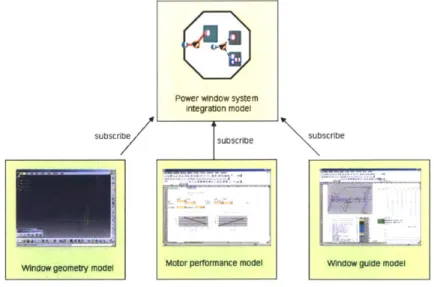
window system used in a car door. The overall configuration of the integration model is shown in Figure 2-1 The integration model is aimed at finding the stall force - a force imposed by a window when its movement is blocked by an object - and the maximum speed of the window. It subscribes a window geometry model to find geometry data such as pillar lengths and glass widths. It also subscribes a motor performance model giving torque and rotational speed and a window guide model calculating the stall force and the maximum speed. Each subscribed model interface has three to twenty parameters. Thos parameters are mapped to each other in the integration model, and as a result a fairly complex integration model having four relations and forty seven mappings is created.
Power window system Integration model
subscribe subscribe subscribe
Window geometry model Motor performance model Window guide model
Figure 2-1: Simulation models for a power window system
After the company evaluates the performance of the current power window system, they are interested in exploring design alternatives. More specifically, they are interested in a motor from a new supplier that provides maximum torque and maximum rotation speed similar to the current motor but has different characteristics in terms of acceleration and electric resistance. They want to
know how the system's performance will change if they replace the current motor with the new motor. Assuming that the company can obtain the new supplier's motor simulation model, two challenging aspects of the replacement task are observed. First, they want to replace the motor simulation model without having to rebuild, meaning to create a new integration model and define all the mappings, the power window system integration model. They want to reuse the integration structure they have defined in the model: the integration structure refers to a graph composed of all the mappings and relations defined in an integration model. Second, the simulation model provided
by a new supplier has a slightly different model interface such as it gives resistance instead of
current Figure 2-2 so mathematical transformation on those parameters will be needed. Inteface of current rrtor modd Interface of new rmtor mode
5
speed at 2 Nm torque 0 speed at 2nm5
torque at 20 rpm speed 0 torque at 20rpm* stall current <- - - - ->
5
stall resistance5
free current <- - - - -> free resistance5
voltage supply5voltage
S
resistance5
resistanceFigure 2-2: Comparison between two motor simulation models
As a first step, the company creates an integration model called motor catalog mxdd,
which has the same model interface definition as the current motor model, and maps all parameters in the current motor model to the corresponding parameters in the model interface. Now the motor catalog model has the current motor simulation as one of its implementation. The second step is to add the new motor simulation model as another implementation of the motor catalog model
Fgre
2- and to set up necessary mappings between parameters in the new motor simulation model and those in the catalog model interface. The last step is to replace the motor simulation model in the power window system integration model with the new motor catalog model and set its implementation switch to the implementation added in the second step. Since both of the replaced
and replacing models have the same interface definition, this step can be done without affecting any mappings or relations in the power window system integration model. In other words, the integration structure of the power window system integration model is reused for another configuration of the integration model.
add implementation rWl-Speed at 2 rlAtorque at 20 reAketam cuwrent
Nrn
H torque qpr speed
Figure 2-3: Adding a new implementation to motor simulation model
Another benefit from using the motor catalog model instead of the previous typical motor simulation model is that we can switch and execute different implementations in the run-mode. While we had to go back to the build-mode to change the configuration of the power window
system and re-deploy the modified integration model, now
just
changing the value of theimplementation switch in the run-mode will activate the selected implementation Figue2-4and
Figure 2-4: Implementation can be switched to another in run-mode
Motor catalog model uising the DOME sew
cunent motor sinulation model ''|*
8Eu
Chanvg ng implement ation Aw tch
Motor catalog model using the DOME
new motor simulation model
DOME server
Figure 2-5: By changing the implementation switch, the configuration of the power window system can be changed from using the current motor simulation model to using the new motor simulation
The difference between two subscribed model interfaces is handled by the mapping with transformation. The new motor model provides noninal voltage and stall resfstance, and therefore stall current can be calculated from them by dividing voltage with resistance. One method of doing such a transformation is to write a procedural relation that transforms voltage and resistance into current. It requires us to create several modeling elements - one relation, three parameters and three mappings - as well as to specify the causality information. While we are defining a simple
transformation, this method increases the complexity of the integration model considerably; therefore it is not considered very efficient. However, with the new integration model, we can do the same task in a simpler way because it supports the mapping with transformation. The mapping with transformation allows us to write a line of mathematical equation in the mapping script editor, and the equation is used to transform source parameter values into a target parameter value. Therefore, a task that used to require several modeling elements can be done with one mapping with transformation 'Figure 2-6
*motor request > speed at 2nm... *torque at 2r...
9
stall currenttype:RWld type:Real type:Real type: Real
u n it nw unit u n itno unid un itrno undt unitno UNit
SZ2Nm rpm *.21 rpm al voltage I
.
orqu tostall resistance
f*ree current
9
voitage %Iktype:Real type:Real P..
unitnouit unitnO unit unitno unit
voltages IfWee voltage resistance
Figure 2-6: Using mapping with transformation to handling differences in interface definition As a result, we can handle the difference in model interface definition in an efficient, manageable way. Note that a parser embedded in the mapping script editor generates causality information for the equation, and users can save time and effort spent on specifying trivial causality information.
2.2. Reuse of the I ntegration Code Pattern
2.2.1. Exemplary reuse problems
Before we describe the reuse scenario of integration code patterns, several exemplary integration code reuse problems will be presented to clarify the focus of our interest in reuse, and they will be solved by examining regularity existing in the integration code.
In Problem 1, we have four parameters, two of which have their mapping scripts completed Figure 2-7 . What would be the mapping scripts for pos3 and po4 then? The answer would be rdB.p[2 and rdB.p[3. One justification is for this intuitive reasoning is the regularity found in two completed mapping scripts, which is called the integration code pattern or the code pattern in short. The code pattern for this problem is expressed using the following set of rules: Text part of the script, rdB.p[ and ], is the same for both mapping scripts, and the number inside brackets is one smaller than the number comes after pos.
Builder GUI reprstnation Text reprsentation
pos1 p082 po_3 *po pos_1 = relB.p[O]
type:Real typeReal tjpe:Real type:Real p0s_2 = relB.p[l]
unit no unit un it no ilt unit n1 unit unitno u3t
p [01 rp [1 pos_3 = ?
p0os 4=?
Figure 2-7: The first example of code pattern generalization problem
Problem 2 has four parameters, three of which have mapping scripts Figure 2-8. What would be the mapping script for a_3_5? Again it is not very difficult to infer that the answer would
be rdB.q[3][5]. We see regularity in three mapping scripts that two numbers inside brackets are the same as the first and second number in the parameter name.
Builder GUI rqeresetnation
Text rqresentation
1 *a-21 la ._2 !$a3 a _1_1 = relB.q[1][1]
type:Real type:Real type:Real type:teal a_2_1 = relB.q[2][1]
un it no unit un it no uit un it no ilt unit no ilt
a_1_2 = relB.q[1][2]
a_3_5=?
Figure 2-8: The second example of code pattern generalization problem
Problem 3 have three parameters with one mapping scripts not completed [Figure 2-9. We are interested to know what would be the mapping script for newDqth. Because two mapping scripts show that a string coming after new in the parameter name is the same as a string that comes after old, the answer would be oldDqeth * 0.5.
Builder GUI rqeressination
Text representation
SnewHeght
*newWldth
*newDepth
newHeight = originHeight * 0.5type:Real type Real type ReW
newWidth = originWidth * 0.5 u n it:no ilt unit no wit u n it:no uilt
re4oIdHelght 0.5 re.oldWIdth 0.5 newDepth=?
Figure 2-9: The third example of code pattern generalization problem
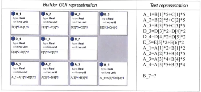
In Problem 4, ten mapping scripts are given, and we are asked to fill a mapping script for
B_7 Figure 2-10 . While previous problems could be explained by one set of rules that applies to
whole examples codes, we can't find such a rule in this case. This problem is not as intuitive as the last three problems, and it may seem unnecessarily complicated. However, this is a more realistic case of the integration code pattern reuse. It reflects the complexity of the environment in which the code pattern reuse should operate: A user provides no explicit information other than which parameter needs code completion. Also, among many mapping scripts in a simulation model, only some of them can be generalized into a rule set that can generate valid candidate, while others can be generalized but their candidate may not be compatible with a given code completion - as we will see in the last solving step of Problem 4, candidates generated by the first and the third rule sets
begin with A_7, which are not acceptable because it is not consistent with the given parameter name B_7 - still others may not even be generalized into a rule set. After several trial-and-error to
generalize rules, B_7=B[7] *2+B[8] *2is found to be an answer based on justification as follows.
Builder GUI rqeresstnation Text rqrestation
1 10A2 A3 00_3 A1I=B[1]*5+C[l]*5
type:Real type:Real type:Real type:Rel A 2=B[2]*5+C[2]*5
unit no unit un it:no unit unit no nit unitno unit
6[1]*5+C[1 1*5 B[21*5+C[2]*5 B[3]*5+C[3]*5 D[3]*2+D[41*2 A_3=B[3]*5+C[3]*5
1_ 11
D_3=D[3]*2+D[4]*2
type:Real type:Real unit:no unit unit:no unit
D[4]*2+D[5]*2 E[5]*2+E[6]*2 D 4=D[4]*2+D[5]*2 E_5=E[5]*2+E[6]*2 A1 =A[]*2+B[l]*2 A_2=A[2]*3+B[4]*5 A 3=A[3]*4+B[A*5 J_
$A_1 I*A2 A_3 A_4 A_4=A[5]*5+B[3]*4
type Real type Real type:Real type Real
un itno unit unit no unit unitno unit unitno uit
A1 =A[ 1*2+B[1 ]*2 A[2]*3+B[4]*5 A[3]*4+6[4]*5 A_4=A[5]*5+B[3]*4 B_7=?
Figure 2-10: The fourth example of code pattern generalization problem
We need three sets of rules to explain all mapping scripts, or all lines in text representation. The first three lines are explained by a set of rules: "A B, C, 5, _, *, [, and ] are the same for each line" and "The number after - is repeated for two numbers in the brackets." The second set of rules
explains the next three lines: "The same text string such as D or E is repeated three times - one at the beginning and two before two [", "The number inside the first brackets is the same as the first
number after _, while the number inside the second brackets is one bigger than it," and "other numbers are the same as 2 for each line." Similarly, another set of rules explains the remaining four lines. Given these three set of rules, now we can create three possible answers. The first and the
third rule sets give A_7=B[7]*2+B[8]*2 and A_7=A[7*8+B[$(N+0}]*$(N+1}, in which
$(N+0} is a placeholder for an undetermined number that should be one smaller than the number at $(N+1). Although the two rule sets have created candidates, their candidates are not acceptable
the second rule set is consistent with the given parameter name B_7, and finally
B_7=B[7]*2+B[8]*2 is displayed as a candidate for the mapping script.
2.2.2.
Scenario of reusing the integration code pattern
Assuming a pattern generalization algorithm that can systematically solve problems described in Section 2.2.1 has been developed, a user will go through the following steps to reuse the integration code pattern. We suppose that a user is working on the same simulation model used in Problem 4. The user just have finished writing mapping scripts for parameter D_4 and E_5 and is about to write a mapping script for B_7. If the design tool did not support automatic code completion based on code pattern reuse, she would copy the mapping script of D_4,
D[4]*2+D[5]*2 and modify it to B[71*2+B[8]*2. Even though changing characters and index
numbers seems to be a trivial task to do, people often miss to modify some indexes and characters, creating a bug in the simulation model. The bug not only generates unexpected, wrong results, but it also requires considerable time and effort to be fixed, especially when it is an index-related bug.
Now that the design tool offers code completion feature, enabling the user to reuse the integration code pattern, the user decides to use it. After having applied the same pattern for the two mapping scripts of D_4 and E_5, the user activates the code completion feature to generate a mapping script for B_7. The code completion feature is accessible either by hitting a space key with control down or clicking a mapping script editor with control down. The list of code completion candidates pops up in the mapping script editor (Figure 2-11). The user finds that B[7]*2+B[8]*2 is the only code completion candidate. After selecting the candidate, the user accepts it either by double-clicking the candidate or by hitting an enter key. Note that the user does not have to provide any extra information to the computer other than which parameter needs code completion. Information such as which mapping scripts should be used as a reference of the code pattern
generalization might be helpful for the code pattern generalization algorithm to solve the problem easily, but requiring such information each time of code completion would make the code pattern reuse process inconvenient and inefficient, possibly damaging usability of the integration code pattern reusing feature. When the code completion finds many candidates, the user has an option to narrow down the candidates by typing more literals, which match the beginning of the desired mapping script.
IOA1 IA_2 OA_3 OA_-4
tvpe:Reai t p Real tvpe Real type Real
unitan unt -im t no unr u nit no unrd u n t no unrd
A[1 ]*2+B[1 ]*2 A[2r3+8[41*5 A[314+B[4]*5 A[5]*5+B[3]'4
10 A_1 A_2 A_3 _3
tvptReal typeReal typeRemal tvpe:Real
-init:no unit unitno unit unitno uit u no unit
B[1 I5+C[1 *5 B[2]*5+C[2*5 B[3]*5+C[3r5 D[3r2+D[4 2
type:Real tpe: Real type:Real
unitno unit u nitmnounr unit no unit D[41*2+D[5]*2 E(51*2+E[61*2
B[7]*2+B[8r2
ty pe:Rfaw Ityp e:l typ :el unitro unit u nit nko unit unitin unit
type Real type.Real unito unit un nounit
Chapter 3 Related Work
This chapter reviews most relevant branches of research that address the issues of software reusability. These include software engineering, user interface design, and data mining. Section 3.1 describes concepts and techniques developed in those disciplines. Section 3.2 discusses the current support of reusability in major integrated design frameworks, identifying what kind of features are missing or need improvement.
3.1.
Approaches
3.1.1. Software engineering approach to reusability
Simulation models being a kind of software, software engineering concepts developed for software reusability is helpful to solve our problem of reusing simulation models. Some of the useful concepts are found in object-oriented programming, which is the most popular programming paradigm to date. Given the list of concepts that characterize the object-oriented programming [1], we have chosen the following concepts since they are closely related to the issue of reusability: instantiation, polymorphism, and inheritance
Instantiation is a concept on the way how an object is created. In a language supporting instantiation, multiple objects can be created from a class. Because behaviors and data structures defined for one class can be reused to create many objects, it improves reusability [2]. Polymorphism is a mechanism that allows multiple implementations to be associated with a class
[3]. It decouples the external representation of a class, called the interface, from its internal
implementations; therefore, programmers can modify implementations without affecting other classes using the class. To implement polymorphism, behaviors of a class need to be chosen based
on the target of the invocation. The implementation dispatching mechanism is used to achieve this in most object-oriented languages [4]. Inheritance is also related to software reusability because it suggests that specialized behaviors of a sub-class be built on the implementation of super-classes.
In addition to concepts derived from object-oriented programming, we have other software engineering concepts, which are also essential to achieve software reusability: composition and interoperability. Composition a concept that allows simple software modules to be combined to build up a complex one [5]. Because it provides a simple, yet powerful way of reusing software components, it is supported by most programming languages. Interoperability is also an important concern for reusability since a software component cannot be reused if it is not accessible to other software components. Some of existing solutions addressing the interoperability issue include COM
[6], CORBA [7], and SOAP [8].
3.1.2. Source code mining approach to reusability
Source code mining is an application of data mining techniques to find relationships and correlations hidden in a large amount of source code [9]. While software engineering approaches described in Section 3.1.1 try to invent new mechanism for reusability and embed it in a programming language, code mining approach focus on how we can use a given programming language in a better way promoting reusability. For this reason, code mining approaches have developed a range of tools that help programmers produce reusable code.
Two categories of the code mining tool are reviewed in detail because they address the similar technical issues we have to deal with when implementing our feature for reusing integration code patterns. The first category is a tool that detects undesirable, not-easily-reusable code fragments, called code clones. The code clone is a code fragment the same or equivalent copies of which are found in another part of source code [10]. It has been reported that code clones degrade
the reusability and maintainability of the software [10-14]. The second category is a tool that helps programmers to find reusable code from a repository of source code. Because the tool automatically completes the remaining part of source code a programmer is working on, it is called
example-based code completion tool.
Research on the code clone detection tool has focused on developing fast and reliable algorithm that can locate the same or equivalent code fragments. We identify two broad approaches, namely, lexical-analyzer-based and textual-pattern-based. The lexical-analyzer-based approach employs a parser to transform a source code into a specialized data structure for clone detection [12, 14]. Such an approach is computationally more expensive than the textual-pattern-based, but has an advantage in detecting non-contiguous code clones because lexical information, such as program dependence graph [14] depicting a relationship among non-contiguous code fragments, can be used. Some of the initial works done in the textual-pattern-based approach suffer from not being able to detect code clones that contain slight modification or span over multiple lines [11, 15]. Later works address this problem by utilizing token-based representation [10, 13, 16]. Because the textual pattern-based approach does not require a parser, which needs to be developed for each programming language, it can be applied in language-independent manner [17], an advantageous aspect over the lexical-analyzer-based approach.
Several example-based code completion tools have been developed based on the code mining technique [18-21]. Code completion is achieved by a two-step process: building a code example repository and querying relevant code from the repository. To perform the first step, each code completion tool has been found to be using different data representation of source code depending on the search algorithms they employ. A code completion tool described in [20] represents source codes with a graph of method signatures because it generates code completion candidates based on a graph search algorithm, while another presented in [21] stores vectors
because its search algorithm is based on structural similarity measured by the vector distance. Regarding the second step, most tools address the issue of automatic generation of search queries
[18-21] because it is an essential feature for code completion feature to be usable: Few
programmers would use code completion feature if they have to learn new query syntax and write a query each time they use it [20].
3.1.3. User interface design approach to reusability
User interface design is a technique to improve usability of an artifact. Based on the assumption that the actual performance of a tool is determined by both the functionality and the usability the tool provides, user interface design is another important technique for reusability. A design tool's user interface that employs appropriate visualization techniques not only improves an engineering designer's understanding of simulation models, but also it increases the chance of applying reuse features of the design tool. Moreover, it reduces the number of mistakes during model editing and reusing. For example, an engineering designer is editing a simulation model having a number of parameters connected by complicated causalities. Because the designer has limited knowledge of the model, he or she may define an erroneous mapping that will cause a loop in causality. Such an erroneous manipulation of simulation models can be prevented by improving the design tool's user interface so that it gives visual feedbacks on causality information. Extensive studies on information visualization techniques along with justification for them based on the recent founding on human vision and cognitive can be found in [22]. Useful guidelines provided by user interface specialists are also available in [23, 24].
3.2.
Challenges
are built, integrated, and reused for engineering analysis. This section aims at identifying reusability problems in current integrated design frameworks. We begin our discussion with a survey result showing how software engineering concepts for reusability, which have been described in Section
3.1.1, are supported in three integrated design environments [25-27] and a simulation modeling
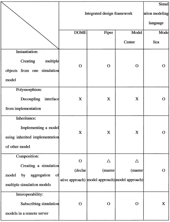
languages [28]. What we observe in Table 3.1 is that even major integrated design frameworks do not support some of the key concepts, while object-oriented simulation languages [28-30], such as Modelica, have a support for them.
Simul
Integrated design framework ation modeling
language
DOME Fiper Model Mode
Center lica
Instantiation:
Creating multiple
O 0 0 0
objects from one simulation model Polymorphism: Decoupling interface X X X 0 from implementation Inheritance: Implementing a model
x
x
x
0using inherited implementation of other model
Composition:
O A A
Creating a simulation
(declar (master (master 0
model by aggregation of
ative approach) model approach) model approach) multiple simulation models
Interoperability:
Subscribing simulation 0 0 0 X
models in a remote server
One way of explaining this difference in support is that some of the object-oriented progranmming concepts are not as effective as they promise for reusability. Interestingly, critics on the object-oriented programming have pointed out that the gain from inheritance is often outweighed by the inflexibility it introduces to a system [31, 32]. Any change to a super-class has far-reaching effects on all its sub-classes [33], and as a result the system gets less flexible in adapting itself for subsequent changes in requirements [31].
In contrast to inheritance, polymorphism is considered as a missing, needed feature for improving reusability. The integration structure reuse, whose benefits have been demonstrated in the use case scenario in Section 2.2, is one application of the polymorphism concept to a simulation model because both - integration structure reuse and polymorphism - share the same key idea of decoupling the implementation from the interface. Thus, by developing integration mechanism implementing the integration structure reuse, we complement the missing support of the key concept in integrated design frameworks. As a platform for developing the integration mechanism,
DOME (Distributed Object-oriented Modeling Environment) will be used. The DOME is an
integrated design framework which has addressed several major reusability issues such as instantiation, composition, interoperability, portability, and user interface design, making it the most reuse-supporting platform among compared integrated design frameworks [25, 26].
We decompose our problem of the integration code pattern reuse into two sub-problems so that we can identify how and which of source code mining techniques can be utilized for our work. The first sub-problem is to find relevant integration code from the whole integration code, and the second is to find rules that capture the regularity within the relevant codes. Based on our discussion on the clone code detection and the example-based code completion, we need to decide which approach will be taken for the first sub-problem: lexical-analyzer-based or textual-pattern-based. The textual-pattern-based approach, more specifically the token-based representation, has been
chosen because we aim to make our pattern reuse mechanism be language-independent and widely applicable to other text editing software components. Some researchers have also found that a relatively simple textual-pattern-based approach for code detection performs effectively when compared to sophisticated lexical analyzer approaches [34]. Other issues such as the code repository organization and automatic query generation can be addressed accordingly based on the code representation scheme, and the solution will be presented in Section 4.4. For the second sub-problem of generalizing rules from the relevant codes, we could not find relevant previous work, so a new mechanism addressing this problem will be developed in Section 4.4.
As for the user interface design of the design tool reusing two kinds of integration knowledge, most of visualization and user interaction techniques discussed in [22-24, 35] are found relevant, and they will be selectively adopted and adapted to meet the design tool's needs. Issues to be addressed by the user interface of the design tool include 2-D structures for parameters, relations, mappings visualization; interaction for model definition and reuse; focus and context management during model navigation; and data mapping for model understanding. Considering a number of useful user interface design techniques available to solve our design problem, the focus of our research, in terms of user interface design, will be exploiting available knowledge to build an effective user interface, specialized in reusing integration knowledge in simulation models. Further details on the application will be explored in Section 4.5.
Chapter 4 Implementation
This chapter describes how we build the design tool for reusing integration knowledge. The first section of the chapter provides an overview of software components. Instead of just showing the end result, the section explains the way how our software components are derived and the reason why they are suitable for our needs. The proceeding sections give details on major
software components: catalog model definition, dependency solving algorithm, pattern
generalization algorithm, and catalog model builder.
4.1.
System Overview
Section 4.1.1 and 4.1.2 formulate and analyze the design of the design tool based on a design methodology called axiomatic design. Further description on the design methodology with extensive application examples can be found in [36].
4.1.1. Functional requirements
We find the functional requirements for the design tool by sequentially following what the system performs and writing down what conditions should be met at each step to proceed. In order to reuse the integration structure, we suppose that the design tool should have a system that performs the following steps. First, the system has a data structure defining modeling elements in an integration model. When the system receives a request for executing a model interface, it looks up the data structure to create an execution plan. The execution plan is translated into an executable form such as script code, which is executed by a script engine. After executing the executable form, the execution result is collected and sent out to the DOME runtime environment. In addition to these run-mode steps, we suppose that following build-time steps are needed. First, the system
provides a programmable interface to create and modify an integration model. Next, based on the programmable interface, the system provides a graphical user interface so that users can easily build integration models.
In order to reuse the integration code pattern, we assume that the system should perform the followings. First, the system needs to store the whole collection of mapping scripts in an integration model; also the collection needs to be queried to find mapping scripts relevant to the parameter name to which code completion is requested. Next, the system is expected to employ an algorithm to generalize patterns from the relevant mapping scripts; the generalized patterns are used to generate code completion candidates. The system should interact with the user interface of the design tool. It provides a programmable interface to access the code completion feature. A user interface component, such as a code completion popup, is integrated with the programmable interface and displays the code completion candidates. The functional requirements for the design tool are summarized as follows (Figure 4-1):
I
~:Reuse integration structure
FRI.1: Manage data structures defining the new integration model
FR1.2: Generate execution plans for the currently selected implementation FR1.3: Provide programmable interface for building integration models FRI.4: Provide user-friendly interface for building integration models
FR1.5: Run the execution plan for the selected implementation
FRl.6: Interface with DOME runtime environment to send out the results
FR2: Reuse integration code pattern
FR2. 1: Retrieve relevant code from the whole collection of code
FR2.2: Generalize patterns, each which is expressed as a rule set, from the retrieved code FR2.3: Generate code completion candidates by applying rule sets
FR2.4: Provide programmable interface for executing the algorithm FR2.5: Integrate the algorithm into design tool user interface
Figure 4-1: Function requirements identified for the design tool
Given the functional requirements, finding design parameters is to find a set of software components that can satisfy all the functional requirements. Because there can be multiple sets of software components satisfying the requirements, we try to come up with a design that is close to an ideal design, characterized by having no coupling within design parameters. Minimizing coupling is an important issue for software components since it significantly affects their reusability. Finally, Figure 4-2 summarizes the design parameters of our design tool.
DP1: Software components for integration structure reuse
DPI.1: Catalog model definition classes
(mit.cadlab.dome3.plugin.catalog.core)
DP1.2: Dependency solver classes
(mit.cadlab.dome3.plugin.catalog.core)
DP1.3: Catalog model builder API classes
(mit.cadlab.dome3.plugin.catalog.core)
DP1.4: Catalog model builder GUI classes
(mit.cadlab.dome3.plugin.catalog.ui)
DPl.5: Groovy Script generator, Groovy script engine, and DOME API
(mit.cadlab.dome3.plugin.catalog, mit.cadlab.dome3.api)
DP1.6: Catalog model plug-in and DOME-specific file generator classes
(mit.cadlab.dome3.plugin.catalog, mitLcadlab.dome3.plugin.catalog.serialization)
DP2: Software components for integration code pattern reuse
DP2. 1: Code repository classes
(mit.cadlab.dome3.plugin.catalog.pcc)
DP2.2: Rule generalization classes
(mit.cadlab.dome3.plugin.catalog.pcc)
DP2.3: Rule application classes
(mit.cadlab.dome3.plugin.catalog.pcc)
DP2.4: Pattern generalziation API classes
(mit.cadlab.dome3.plugin.catalog.pcc)
DP2.5: Code completion popup classes
(mit.cadlab.dome3.plugin.catalog.ui)
Figure 4-2: Design parameters identified for the design tool
We analyze the design matrix shown in Figure 4-3 to evaluate how desirable our selection of design parameters is. Design matrix visualizes which design parameters are used to satisfy a certain functional requirement; for example, to satisfy FR1.2 Generate execution plan, we use two
components for the catalog model definition and the dependency solving algorithm. Generally, uncoupled or decoupled design is considered as an acceptable design because all FRs can be satisfied by choosing DPs in a certain sequential order, which can be solved from the design matrix. As Figure 4-3 shows, our design matrix is a decoupled one, having only lower triangular elements.
DPI DP2
a)
E E 0
FR1. roramabl Prvid 0nerfce CXC
.A_- C:4'k FR14 Povdo oerfrendCineraceX FR4.6 I- I r wta) 0 W 0 -9 CL C L. Utn -~- U or Ln CL2 F2 Gd Cd 0 03 0 0 0 > 3 CL 0 15- W. 0 .~ -" - i" (U03 U (D Cy. 0 o A U 0 F c. Pb X a
FR2) int usa an)gt rnec -a X
'n-40 mD 'C C) C, W-4 0 - C 0~
0 C-0-0-44 0 01 CS M1 "
Figure 4-3 DesFg maFru sh3in F -:seaisi af aur new Dg a) U. 0i U U CL 0. .C L
FRiyaManage data structures X
FR 1. 2 bGenerate executi on pan d . X X
FR1.3eProvide programm able interface X X X
LL~ FR1.4:Provide user-friendly interface X X
FRe.5Run execution plan X X
e FR.6fInterface with DOME P x f eX ep
FR2. 1e : Retrieve relevant code X
FR2,2iGeneralize patterns X X
cc FR2.3::Generate candidates X X
FR2.4: Provid e pro ram m abl e i nterface __X XIX X _
11FR2.SiIntegrate into user interface IIX X
Figure 4-3: Design matrix showing FFP-DPS relationship of our new design tool
Modularity analysis on the design matrix reveals that our concern on the reusability of software components has been effectively addressed. Some of our software components such as the dependency solving algorithm and the pattern generalization algorithm are elaborated implementation works, and thus we want to organize the software components so that those expensive components can be used for other applications. FR1.5