DEVELOPMENT OF AN EFFECTIVE COMPUTATIONAL
METHODOLOGY FOR MULTI-STAGE COMPRESSOR MAP
GENERATION
by
TAEK JIN CHOI
B.S. Mechanical Engineering, Carnegie Mellon University, 1997 M.S. Mechanical Engineering, Carnegie Mellon University, 1999
Submitted to the Department of Aeronautics and Astronautics in partial fulfillment of the requirements for the degree of
MASTER OF SCIENCE
at the
MASSACHUSETTS INSTITUTE OF TECHNOLOGY
AFRO
September 2001
C 2001 Massachusetts Institute of Technology. All rights reserved. MAsSACHUSSETS STJ T
OFTECH OGY
AUG 1 3 2002
LIBRARIES Author Certified by Accepted by.. .bepartment of Aerpr"utics and Astronautics July 27, 2001
Dr. Choon Sooi Tan Senior Research Engineer Thesig Supervisor
Professor Wallace Earl Vander Velde Professor of Aeronautics and Astronautics Chair, Committee on Graduate Students
DEVELOPMENT OF AN EFFECTIVE COMPUTATIONAL
METHODOLOGY FOR MULTI-STAGE COMPRESSOR MAP
GENERATION
by
TAEK JIN CHOI
Submitted to the Department of Aeronautics and Astronautics on July 27, 2001 in partial fulfillment of the requirements for the degree of
Master of Science
ABSTRACT
A framework for effective computational methodology was developed for multi-stage
compressor map generation. The methodology consists of using a few isolated-blade row Navier-Stokes solutions for each blade row to construct a body force database. The purpose of the body force database is to replace each blade row in a multi-stage compressor by a body force distribution to produce same pressure rise and flow turning. To do this, each body force database is generated in such a way that it can respond to the changes in local flow conditions. Once the database is generated, no further Navier-Stokes computations are necessary. The process is repeated for every blade row in the multi-stage compressor. The body forces are then embedded as source terms in an Euler solver. The method is developed to have the capability to compute the performance in a flow that has radial as well as circumferential non-uniformity with a length scale larger than a blade pitch; thus it can potentially be used to characterize the stability of a compressor under design. It is these two latter features as well as the procedure to obtain the body force representation that distinguish the present methodology from the streamline curvature method.
The overall computational procedures have been developed. A dimensional analysis was carried out to determine the local flow conditions for parameterizing the magnitudes of the local body force representation of blade rows. An Euler solver was modified to embed the body forces as source terms. Four test cases were performed to validate and assess the current methodology. The results from the dimensional analysis show that the body forces can be parameterized in terms of the two relative flow angles, the relative Mach number, and the Reynolds number. For the flow in a high-speed transonic blade row, they can be parameterized in terms of the local relative Mach number alone. It is deduced that the performance and the flow distribution of a single blade row subjected to radial inlet distortions can be predicted using the body force database created from the Navier-Stokes solutions with uniform inlet conditions. Likewise, the performance at an operating point, other than those from which the database for the body forces were extracted, can be computed as well.
Thesis Supervisor: Dr. Choon S. Tan Title: Senior Research Engineer
ACKNOWLEDGEMENTS
I would like to express my gratitude to Dr. Choon S. Tan for giving me an opportunity to
work on this exciting research project. I also wish to thank Dr. Yifang Gong for giving me a version of his Euler code, guidance, and insightful comments, and Mr. Jim Bleeg of Pratt & Whitney Aircraft Engine for proving me with invaluable RANS solutions. I am indebted to Professor Frank E. Marble of California Institute of Technology and Professor Nick A. Cumpty of Whittle Laboratory at Cambridge University for their
inputs on this work.
Without a doubt, the graduate students of MIT Gas Turbine Laboratory have made my two years of MIT experience a pleasant one. I especially thank Duc Vo and Bobby Sirakov for interesting conversations about life, culture, and politics. Coffee breaks with Dongwon and Hyung-soo helped me stay awake for debugging the computer programs and running numerical computations. I also would to thank Simon Evans, Zack Warfield, and Laurent Jamonet for being wonderful officemates.
I would also like to take this opportunity to thank Professor Tom I-P. Shih of the Engine
Laboratory at Michigan State University for introducing me to the fascinating field of computational fluid dynamics when I was an undergraduate student at Carnegie Mellon University. I have benefited enormously from his constant motivations, guidance, and insights for excellence. Without him, I would not have made it this far.
Finally, I would like to dedicate this thesis to my mother, Sun Hae Choi, for her enormous sacrifice and forbearance while I pursued my undergraduate and two graduate degrees for the last eight years.
This research was supported by a MIT Presidential Graduate Fellowship, Pratt & Whitney Aircraft Engine under Contract Agreement Number 98-023 with Drs. Mark Barnett and Bob Ni, and Mr. Mark Aubuchon as technical monitors, and NASA Glenn Research Center under Grant Number NAS3-2101 with Dr. Ken Suder as technical monitor. Their support is gratefully acknowledged.
CONTENTS
Abstract... 2
A cknow ledgem ents... 3
L ist of F igures... 8
List of Tables... ... 11
1. Introduction... 12
1.1. Background... ... 12
1.2. Motivation of the Research... 15
1.3. A Brief Review of Previous Work on Use of Body Forces in Turbomachinery... 19
1.4. A Comment on Present Methodology vs. Streamline Curvature ... 20
1.5. Research Objectives... 21
1.6. Contribution of the Thesis... 22
1.7. Organization of the Thesis... 23
2. Development of Computational Methodology: Part I... 25
2.1. Introduction... 25
2.2. Body Force Formulation... 25
2.3. Main Advantages of Model... 27
2.4. Overall Computational Procedure... 29
2.4.1. Procedure for Concept Validation... 29
2.4.2. Procedure for Flow Prediction with a Body Force Database... 31
2.5. Body Force Extraction... 33
2.5.1. Computing Body Forces... 34
2.6. Governing Equations... 37
2.6.1. Flow in D ucts... 37
2.6.2. Flow in Blade Rows... 37
2.7. Numerical Method of Solutions... 39
2.8. Summary... 40
3. Development of Computational Methodology: Part II... 41
3.1. Generation of Body Force Database... 41
3.1.1. Parametric Representation of Body Forces... 42
3.1.1.1. Dimensional Analysis... 42
3.1.1.2. Subsonic Flows... 43
3.1.1.3. Supersonic Flows... 44
3.1.2. Generation Procedure... 45
3.2. Potential Engineering Applications... 45
3.2.1. Response to Radial Inlet Distortions... 45
3.2.2. Performance of a Multi-Stage Compressor... 47
3.3. Summary... 49
4. Description of Test Cases... 50
4.1. Introduction... 50
4.1.1. More Details on NASA Rotor 37... 51
4.2. Test Case 1: Validation of Applicability of Model... 51
4.2.1. Description of Navier-Stokes Solutions... 52
4.2.2. Description of Euler Computation with Body Forces... 55
4.3. Test Case 2: Redistribution of Body Forces... 56
4.3.1. Description of Navier-Stokes Solutions... 57
4.3.2. Description of Euler Computation with Body Forces... 59
4.4. Test Case 3: Radial Inlet Distortions... 60
4.5. Test
4.4.2. Description of Euler Computation... Case 4: IGV-Rotor-Stator Configuration...
4.5.1. Description of Isolated-Blade Row Navier-Stokes
Solutions...
4.5.2. Description of Multi-Blade Row Navier-Stokes S olution s... 4.5.3. Description of Euler Computation... 4 .6. Sum m ary ...
5. Results and Discussions... 5.1. Test Case 1: Validation of Basic Model...
5.1.1. Generation of Body-Force Grid System...
5.1.2. Interpolation of Original Navier-Stokes Solutions... 5.1.3. Extraction of Body Forces...
5.1.4. Comments on New Averaging Techniques...
5.1.5. Computational Results...
5.2. Test Case 2: Redistribution of Body Forces...
5.3. Test Case 3: Radial Inlet Distortions... 5.4. Test Case 4: IGV-Rotor-Stator Configuration...
6. Summary, Conclusions, and Future Work ...
6.1. Summary and Conclusions...
6.1.1. Sum m ary ... 6.1.2. C onclusions... 6.2. Recommendations for Future Work...
7. R eferen ces... 61 63 63 65 65 67 68 68 68 69 70 71 71 85 92 98 100 100 100 102 102 105
LIST OF FIGURES
1.1 Compressor performance map and the effects of inlet distortions... 13
1.2 Empirically based compressor design system... 14
1.3 Three-dimensional Navier-Stokes calculation-based design system... 15
1.4 M ixing plane approach... 16
1.5 Average passage approach with body forces and deterministic stresses... 17
2.1 Computational Methodology... 26
2.2 Three-dimensional illustration of the model using the body force distributions... 27
2.3 Conventional CFD multi-stage analysis... 28
2.4 New Multi-stage analysis with body force distributions... 29
2.5 Computational methodology for concept validation... 30
2.6 Generation of a body-force database... 31
2.7 Computational procedure for compressor map generation... 32
2.8 Three-dimensional control volumes and axi-symmetric control volumes.... 35
2.9 Axi-symmetric control volume in a blade row... 35
3.1 An example of the body-force database organization at each local point.... 46
3.2 Utilization of body-force database for non-uniform inlet conditions... 48
4.1 Two-dimensional view (x-r plane) of the Navier-Stokes grid system... 53 4.2 x-0 plane of the Navier-Stokes grid system at a constant radial location
near the m id-span ... 53 4.3 Two-dimensional view of the Euler grid system used... 56 4.4 Two-dimensional representation of the Navier-Stokes solutions for
test case 2 ... 57 4.5 Total-pressure rise characteristic curve of NASA Rotor 37 on its
speed-line... 58
4.6 Two-dimensional representation of the Euler grid system used for
assessing the applicability of the body-force distribution... 60 4.7 Comparisons of inlet total pressure profiles... 62 4.8 Comparisons of inlet axial velocity profiles... 62 4.9 Two-dimensional view of IGV-rotor-stator configuration of HPC for
N avier-Stokes solutions... 64 4.10 Two-dimensional view of IGV-rotor-stator configuration for the Euler
com putation ... 66
5.1 Original Navier-Stokes grid system and body-force grid system... 74 5.2 Comparisons of flow quantities between the original Navier-Stokes
solutions and the interpolated solutions... 75
5.3 Mass-averaged one-dimensional profiles of total-pressure rise and entropy
rise in the axial direction obtained from the interpolated solutions... 76
5.4 Pitchwise-averaged body forces... 77 5.5 One-dimensional profiles of mass-averaged body forces... 78
5.6 Comparisons of one-dimensional profiles of averaged flow solutions
for test case 1... . 79
5.7 Illustration of cross sections chosen for comparisons of
two-dimensional radial profiles... 80
5.8 Comparisons of radial profiles prior to the leading edge from test case 1... 81
5.10 Comparisons of radial profiles after the trailing edge from test case 1.83
5.11 Comparison of pressure-rise characteristics from test case 1... 84 5.12 Comparisons of one-dimensional profiles of averaged flow solutions from
operating point 4 (test case 2)... 87
5.13 Comparisons of radial profiles prior to the leading edge
from operating point 4 (test case 2)... 88 5.14 Comparisons of radial profiles at the mid chord
from operating point 4 (test case 2)... 89
5.15 Comparisons of radial profiles after the trailing edge
from operating point 4 (test case 2)... 90 5.16 Comparisons of pressure-rise characteristics for three operating
points from which the body-force database was generated... 91
5.17 Comparisons of one-dimensional profiles of averaged flow solutions
from the radial inlet distortion case (test case 3)... 93
5.18 Comparisons of radial profiles prior to the leading edge
from the radial inlet distortion case (test case 3)... 94
5.19 Comparisons of radial profiles at the mid chord
from the radial inlet distortion case (test case 3)... 95
5.20 Comparisons of radial profiles after the trailing edge
from the radial inlet distortion case (test case 3)... 96
5.21 Comparisons of pressure-rise characteristics between
the uniform inlet and radial inlet distortion cases (test case 3)... 97
5.22 Preliminary results showing one-dimensional profile of averaged
LIST OF TABLES
1.1 Navier-Stokes grid systems for the multi-stage configuration... 1.2 Euler grid systems for the multi-stage configuration...
64
CHAPTER 1
INTRODUCTION
1.1
Background
Considerable advances in compressor design methodologies have been made since the first gas turbine aircraft engines were developed in late 1930s and early 1940s. Designs have been developed based on one-dimensional mean-line analyses coupled with cascade data, and they often involved numerous iterations between design and testing until satisfactory configurations were found. Radial Equilibrium and Streamline Curvature methods [3], [18], [22], brought the analytical design method from one to two dimensions (axi-symmetric), and led to improved first bench test performance. By 1970s, the two-dimensional methods were matured considerably and used extensively in industry for complete engine analyses and designs. Such methods have enabled the designers to reduce the number of design iterations for engine product development.
The aerodynamic performance of a compressor from design or testing is given as a plot of pressure rise as a function of corrected mass flow rate for each compressor speed. Such a figure is known as a compressor performance map. Further analyses such as compressor stability analysis using the compressor performance characteristics are possible.
A point of instability is reached at which the pressure rise is a maximum and further
compressor. Once a series of the instability points are identified for a range of operating speed, they are connected by what is called a surge line. The surge line is defined by the limit in pressure ratio, for each compressor speed, beyond which the flow in the compressor breaks down in some way so as to make the system no longer operable [11]. Predicting the condition at which instability will occur in a compressor is an essential part of the design process.
7.0
Operating line
Surge line -'
\
StallI6.0 margin 0 3-Figure 1.1: 5.0 4.0 -91% 86% of design 80% rotational speed 25 30 35 40 45 50
Corrected mass flow
Compressor performance map and the effects of inlet distortions [19]
When the compressor map for a design is first generated, either numerically or experimentally, it represents the compressor performance under normal operating conditions. However, there are many uncertainties related to instability: uncertainties of prediction for a given design and uncertainties associated with the conditions of operation. Uncertainties of operation include inlet distortions (Figure 1.1), which may be transient; transient throttle changes, such as occur when an engine is accelerated; transient geometry changes such as tip and axial clearance changes following speed
changes; and compressor mechanical damage including blade erosion and the effects of large foreign body ingestion [3]. Predictions of the compressor performance under all those uncertainties are difficult, if not impossible. However, such capability will enable compressor designers to quantify stability characteristics of compressor designs related to the uncertainties and make significant performance improvements.
During the past two decades, computational fluid dynamics (CFD) has been playing an increasing role in the development and advancement of compressor design and analysis. Modem design methods can, in principle and to some extent in practice, utilize CFD results rather than experiments [13]. This is due to the increasing availability in
computer resources (speed, memory, and data storage) and the considerable advances made in CFD algorithm. Figure 1.2 depicts a typical empirically-based design system tied to a two-dimensional CFD analysis tool. A key goal in industry today is to develop a three-dimensional computer-based compressor design and achieve the expected performance at the first bench test.
Mean-line program selects work distribution and defines velocity triangles
Streamline program checks radial loadings and defines airfoil cross sections
2D viscous CFD checks airfoil surface loadings and verifies turning and loss
Research rig tests block performance
Full-scale rig tests stage matching and overall performance
Engine Test determines integrated performance
The increasing computing power has enabled computations of three-dimensional flow in turbomachines. Such computations, applied to single blade rows or single stages, have led to considerable reduction in compressor design time cycles, and have helped develop innovative ideas for blade designs leading to substantial performance improvements [13]. However, three-dimensional Navier-Stokes computations in a multi-stage compressor are not yet achievable in amounts of time acceptable for design purposes without massive parallel computing resources. A compressor design system based on three-dimensional Navier-Stokes calculations is shown in Figure 1.3.
Mean-line program selects work distribution and defines velocity triangles
_4 Streamline program checks radial loadings and defines airfoil cross sections
K
Figure 1.3:
1.2
I
2D Viscous CFD checks airfoil surface loadings and verifies turning and loss
3D viscous CFD tests stage matching and overall performance
Full-scale rig tests stage matching and overall performance
Engine Test determines integrated performance
Three-dimensional Navier-Stokes calculation-based compressor design system [13]
Motivation of the Research
As direct multi-stage computations cannot be used for multi-stage compressor designs, approximations that are adequate for design and analysis purpose must be made between two neighboring blade rows. One of the most commonly used approximations is the
I Mean-line program selects work distribution and defines velocity triangles I f
mixing plane approach [5]. For example, in the process of using this approach, the rotor is first designed using the mixed-out upstream conditions of the downstream stator as the outflow boundary conditions. The mixed-out rotor outflow conditions are then used as the inflow boundary conditions for the downstream stator design (see Figure 1.4). Since each blade row is designed individually, this leads to an essentially steady design method that does not reflect the impact of any unsteady phenomenon on the compressor performance.
SFauere.ge b~un~y"Pc=Znsboundary downMareamcondtiorm
Mixed-ou1 stalor ilet boundary coinclons
Mie/m oo
(/1 oudr onsfn
However, it has been known that unsteady interactions between two adjacent blade rows can play an important role in determining the maximum pressure rise and efficiency of a compressor. It has been shown that blade row spacing between two blade rows has a significant impact on the compressor performance [9], [16], [23].
For this reason, there [21] has been an attempt to implement an approximate technique for incorporating periodic unsteadiness by modifying the average passage approach of Adamczyk [1], [17], which employs the concept of bodyforces and deterministic stresses (see Figure 1.5). In this method, the body forces introduce a potential interference effect
by establishing a "target" radial static pressure profile at the interface plane between
closely coupled rows, and the deterministic stresses account for the "average" wake blockage and mixing effects both axially and radially. This new approach has been shown to be effective in incorporating the unsteady interaction phenomena into a multi-stage compressor design. However, a full three-dimensional Navier-Stokes computation for an entire multi-stage compressor is still required to use it, with considerable computing resources.
Bodyforces Applied to Downstream Only I Overlapped 1+1 +111 Cornputationa Domain Actual Ps Profile bf Interpolated from -- Downstream Sol. bf Radial Equi librium Upstreamn Extension
Several mechanisms of blade row interaction, and their impact on compressor performance, have been studies previously. The reader should refer to the work by Valkov [25] for a comprehensive review about the mechanisms. In general, the blade row interaction can be classified in two types: potential and vortical. Potential interaction is the impact of the blade row pressure field on the upstream and downstream blade rows. Vortical interaction represents the effect of vortical structures, e.g. wake, tip vortex, stream-wise and corner vortices, on downstream blade rows. Both forms have been shown, analytically and experimentally, to have impact on the compressor performance.
Even though these mechanisms have been studied in the past, this has only been done on the level of a single compressor stage and thus the overall impact of the mechanisms on the level of the entire multistage compressor has not been yet quantified.
Thus, there is a need for an adequate and effective methodology for the generation of multi-stage compressor performance map. This new methodology should (1) incorporate the correct flow interaction phenomena between two neighboring blade rows in a multi-stage compressor, (2) generate multi-multi-stage compressor map for performance evaluation on an effective and adequate basis, and (3) achieve the aforementioned goals with computationally manageable resources.
Hence, the overall goal of the research is to develop and demonstrate an adequate and effective methodology for multi-stage compressor computations that yield compressor maps for design purposes.
1.3
A Brief Review of Previous Work on Use
of Body Forces in Turbomachinery
The concept of using body force distribution to represent a blade row is not new. It has been used by Marble [15], Horlock and Marsh [10], Denton [4], and Adamczyk [1] among others. Escuret and Gamier [6], Longley [14], and Gong [8] have recently used body force distributions to simulate instability inception in a low-speed multi-stage
compressor by long- and short-wavelength disturbances.
Marble has developed an axisymmetric body force model for through-flow computations in blade rows. This body force can be viewed as the distribution of the force applied by the blade on the flow, which can be decomposed into a normal pressure force and a tangential shear force. Marble's model can be implemented if the blade geometry and various flow variables at the blade surface are known.
Horlock and Marsh showed, by averaging the two-dimensional differential form of the continuity and momentum equations across a blade passage, that two-dimensional blade rows in steady inviscid flow can be replaced by distributed body forces. The computation of their body forces requires the knowledge of the static pressure on the blade surface.
Denton used distributed stream-wise body forces to simulate viscous effects in a flow otherwise computed using an inviscid solver. He showed that the pitch-wise profile of body forces could be arbitrarily chosen, provided they create the correct shear force at the blade surface, which is the input in the construction of his model.
Adamczyk showed by applying three averaging operators on the three-dimensional unsteady Navier-Stokes equations that unsteadiness resulting from a multi-blade row environment can be captured on an averaged basis by a steady computation using distributed body forces, heat sources and deterministic stresses. The model elements are
obtained by the application of a closure model, in the same way as a turbulence model is used to obtain Reynolds stresses in a turbulent flow computation.
Escuret and Gamier demonstrated the capability of using a body force distribution for simulating the development of instabilities in multi-stage axial compressors. They used a three-dimensional unsteady Euler code coupled with the body force distribution based on multiple through-flow solutions within blade rows. The model was developed for predicting the growth of only long-wavelength instabilities.
Longley developed a computational model for the moderate to long-wavelength instabilities of high-speed multi-stage compressors. In his work, the flow outside the blade rows was computed using a two-dimensional Euler solver while the individual blade rows were modeled using multiple one-dimensional flow fields with body force distributions.
Gong had developed a model for simulating axial compressor stall inception associated with both long- and short-wavelength disturbances. Individual blade rows were represented by a body force distribution formulated in terms of the blade's pressure rise and flow turning characteristics. The computational model uses a body force distribution that responds to local flow conditions. To achieve this, knowledge about the compressor performance and geometry must be known prior to modeling.
1.4
A Comment on Present Methodology vs.
Streamline Curvature
As alluded to in the above, current/modern thinking on stability modeling involves viewing a compressor blade row as a body force distribution. In the past, the body force representation was based on correlation and meanline analysis as was implemented in streamline curvature and throughflow methods in implicit terms. However, the present
proposed methodology, to be described later, explicitly obtains the body force representation of each blade row in a multi-stage compressor from the "best" available three-dimensional Navier-Stokes solver on a physically consistent basis.
Whereas a streamline curvature method or throughflow analysis is only capable of computing turbomachinery performance in a flow with radial flow variations, the technical framework under which the present proposed methodology is implemented in such that it can compute the performance in a flow that has radial as well as circumferential variations (with length-scales larger than the blade pitch). As such, it can potentially be used to characterize the stability of a compressor under design. It is these two latter aspects, namely how body force representation of a blade row is constructed and the ability to deal with a flow with circumferential non-uniformities, that distinguish the present method from the others.
1.5
Research Objectives
The methodology to be considered and developed here consists of replacing each blade row by an equivalent body force distribution to produce correct pressure rise and flow turning. This methodology must be designed to be computationally feasible while retaining the effect on performance of the important flow features in the entire multi-stage compressor.
The research objectives are as follows:
1. To develop an adequate computational procedure for generating row-by-row
body force representation of high-speed transonic compressors
2. To assess the applicability of the model for multi-stage flow analysis and design feasibility by comparing against multi blade row CFD computations
3. To enable its integration into a compressor design system for generating
compressor map
Modeling is first addressed for a steady state rotor blade row under uniform inlet flow conditions to understand the key concepts. The adequacy of the model is then validated with the same configuration subjected to radial inlet distortions. The model is then extended further for an IGV-rotor-stator configuration to assess the applicability for multi-stage compressor analysis and design. Having completed these steps, the methodology will be applied for performance prediction of a compressor subjected to circumferential inlet distortions and for stability characterization.
1.6
Contributions of the Thesis
The major contributions of the present thesis are as follows:
1. A computational methodology was developed to perform numerical
computations for efficient compressor map generation. The methodology consists of developing computer programs to generate a pitch-wise-averaged body force distribution from isolated blade row Navier-Stokes solutions by considering an integral form of the momentum equation for each control volume.
2. A dimensional Analysis using the 1-Theorem was performed to identify the key parameters that can parameterize the local body forces. They are the two local flow angles (radial and tangential), local relative Mach number, and Reynolds number. For a high-speed transonic compressor, it was deduced that the body forces are only a function of the local relative Mach number. Multiple Navier-Stokes solutions for an isolated high-speed blade row were
used to parameterize the forces and construct a body force database based on this conclusion. The database enables the body forces to responds to the local
flow condition.
3. The implementation of the model was validated with several test cases by
performing numerical computations of a rotor blade row and by comparing the corresponding solutions against the original Navier-Stokes solutions. It was demonstrated that the body force database created from isolated blade row calculations is able to accurately predict the performance of a single blade row subjected to radial inlet distortions based on the computational results obtained from the test cases. Furthermore, the applicability of the computational model developed in this thesis was shown to be encouraging for a multi-stage compressor. The computational methodology is expected to predict the performance of the blade row subjected to circumferential inlet distortions and for detailed stability characterization associated with both long- and short-wave disturbances.
1.7
Organization of the Thesis
The main ideas associated with the body force formulation are first illustrated by the presentation of the physical concepts and the development of a basic computational model in Chapter 2.
In Chapter 3, new capabilities added to the existing model are assessed and validated via the following two levels: local and system level. On the local level, the applicability of the model is first assessed by an extraction of the appropriate body force representation of an isolated blade row and subsequently by a successful replication of the flow field by applying the new representation. Having accomplished the first step, a dimensional analysis is carried out to identify a set of local flow parameters that set the magnitudes of
the forces. The use of this set of the local flow parameters for correlating the response of the body forces with respect to the changes in local flow conditions is illustrated for a blade row subjected to a non-uniform inlet flow.
The model is then further extended to the system level. On this level, adequacy of the body force formulation for multi-stage compressor map generation is assessed by the reconstruction of the flow field in an entire multi-stage compressor by the use of the body force distributions extracted from isolated blade row calculations of individual blade rows in the compressor. The main goal of this level is to demonstrate if uncoupled isolated blade row calculations can be employed to construct an accurate and physically meaningful flow field in the multi-stage compressor.
In Chapter 4, four test cases considered for the validation of the concepts developed on the local and system levels are described, and the corresponding results and discussions are provided in Chapter 5.
Finally, summary and conclusions are presented on the overall performance of the computational methodology are presented in Chapter 6, and guidelines are provided for future work.
CHAPTER
2
DEVELOPMENT OF COMPUTATIONAL
METHODOLOGY: PART I
2.1 Introduction
The first part of the computational methodology using the body force formulation developed in the present research is described in this chapter. Preliminary concepts and basic problem formulations are covered in this part of the development process. Direct extensions of the concepts, formulations, and further analyses are presented in Chapter 3. The first part consists of (1) presenting the main idea of a body force formulation; (2) major advantages of using the body force formulation over standard computational methodologies that are currently being used in industry for multi-stage simulations; (3) overall computational procedure involved to assess the degree of validity of the basic body force concept; (4) steps involved for extracting the body forces; (5) formulation of the new governing equations for the flows in ducts and in blade row regions; (6)
presenting the numerical methods of solutions; and (7) a summary.
2.2 Body Force Formulation
As it was mentioned in the introduction, the first part of the computational methodology begins with the presentation of the body force formulation. A simple graphical
representation is shown in Figure 2.1. Figure 2.1(a) represents a conventional CFD approach, e.g. three-dimensional Navier-Stokes analysis, to compute the flow in a blade row. Figure 2.1(b) shows the axi-symmetric Euler approach with the basic body force representation to produce the identical flow turning and total-pressure rise: the effects of the blade geometries are replaced by equivalent local body forces. Figure 2.2 illustrates the body force methodology in a three-dimensional view. At each point within the blade row, the body forces can conveniently be described in terms of their three components: F, FO, F, i.e. the axial, tangential, and radial forces, respectively, or a component normal to the flow and a component parallel to the flow.
(a)
Figure 2.1:
LI
(b)
Computational methodology: (a) conventional CFD approach and (b) axi-symmetric Euler with body force approach
Fe F o eF
Axi-symmetric Euler with body forces
Figure 2.2: Three-dimensional illustration of the model using the body force distributions [8]
2.3 Main Advantages of Model
There are many advantages of using the axi-symmetric Euler with the body force approach over conventional CFD methodologies based on three-dimensional Navier-Stokes equations. However, two key advantages are described in this section. Replacing the blade rows in a multi-stage compressor by the equivalent body force distributions leads to significant improvements in terms of computational costs. The rest of the section is devoted to provide the explanation for the claim.
First, the new computational methodology makes use of an axi-symmetric Euler CFD code with body forces embedded as source terms in the governing equations. Here, intra-blade-row regions, and upstream and downstream ducts are assumed to be inviscid, while viscous effects are accounted for inside the blade rows. Hence, the number of required grid points is significantly reduced since detailed flow features such as boundary layers,
shear forces, and tip clearance flows do not need to be resolved. However, their effects are reflected in the body force representation.
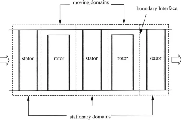
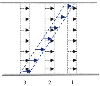
Second, an entire multi-stage compressor computation requires only one computational domain. Typically, for the conventional three-dimensional Navier-Stokes analysis, the total number of computational domains needed is equal to the number of the blade rows in a multi-stage compressor. It is because the rotor-blade-row domains rotate at an angular speed with respect to that for the stator blade rows, as illustrated in Figure 2.3.
moving domains
boundary Interface
--- r--- --- Y---
---0Z
stator rotor stator rotor stator Iz~- - - - - - - -I --- ---- ---- -
---stationary domains
Figure 2.3: Conventional CFD multi-stage analysis: each dashed rectangle represents a computational domain.
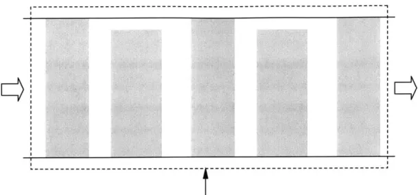
The body force approach eliminates this requirement: the entire multi-stage compressor is modeled as one stationary annulus duct with the effects of the blade rows being substituted by the equivalent body force distributions, as shown in Figure 2.4.
One stationary computational domain
Figure 2.4: New multi-stage analysis with body force distributions: each shaded rectangle represents an equivalent body force representation of the blade. Only one computational domain is required.
2.4 Overall Computational Procedure
In this section, the overall computational procedures are presented. Two flow charts are provided to illustrate the procedures involved in validating the basic body force concept (Figure 2.5) and to calculate the compressor performance using the appropriate body force database (Figure 2.6). More details on the procedure for calculating compressor performance prediction will be presented in Chapter 3.
2.4.1
Procedure for Concept Validation
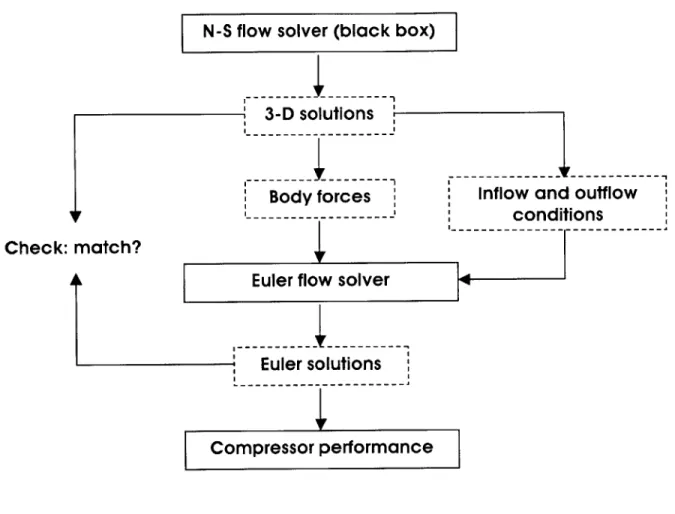
In the beginning of the process, a Navier-Stokes solver is first used to obtain detailed three-dimensional flow solutions at a mass flow for a given isolated blade row. From the solutions, body forces are extracted by solving the integral form of the momentum equations around the control volumes. The extracted body forces are then substituted as
source terms in an Euler flow solver. For the validation step, an Euler computation is performed with the inflow and outflow boundary conditions used to obtain the
Navier-Stokes solutions from which the body forces were extracted.
N-S flow solver (black box)
3-D solutions
Body forces
I..
Inflow and outflow
conditions
-- -- - - - --
-Check: match?
Euler flow solver
Euler solutions
Compressor performance
Figure 2.5: Computational methodology for the concept validation
Having obtained the Euler solutions, one- and two-dimensional mass- and area-averaged profiles of flow variables at various cross sections along the axial direction, as well as the compressor pressure rise computed from the Euler solutions, are compared against the Navier-Stokes solutions.
2.4.2
Procedure for Flow Analysis with a Body Force
Database
The procedure for practical applications involves two steps. The first step consists of generating a body force database for a given blade row (or a set of blade rows). This step is illustrated graphically in Figure 2.6. A Navier-Stokes solver is first used to compute detailed flow fields at various mass flows on a constant speed-line. From the Navier-Stokes solutions, a body force database is constructed. Once the database is available, no further Navier-Stokes computations are required. This step is performed for each blade row in a multi-stage compressor.
N-S flow solver (black box)
A series of 3-D solutions
Body force Database
Figure 2.6: Generation of a body force database
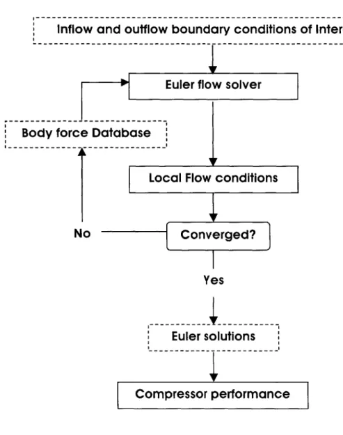
Using the body force database, the performance map generation for the compressor under different inflow boundary conditions are carried out using the axi-symmetric Euler solver. Having specified the inflow and outflow boundary conditions of interest in the beginning of a computation, the solver computes the appropriate local flow conditions and residuals at each iteration. If the flow variables converge, the solutions are produced, and the computation is terminated. If not, the local flow conditions are fed into the database to compute correct local body forces and another iteration is performed with the new body forces. This step is repeated until the solution variables converge to a steady
state. Once the converged solutions are produced, the compressor performance is computed.
The whole procedure is repeated with various inflow and outflow boundary conditions and rotating speeds of the rotor blades that are representative for all possible operating conditions until the complete map is obtained.
Infowan-u--o-budayr---Inflow and outflow boundary conditions of Interest
Body force Database
No
Yes
Euler solutions
Compressor performance
2.5
Body Force Extraction
This section will describe how a body force field is constructed quantitatively for a given blade row in steady flow at a given operating point. In order to quantify the body forces in the field, it is necessary to know pieces of information about the blade row regarding geometry, operating/boundary conditions, and their corresponding flow field. Depending on the level of accuracy desired, the amount of information required to model the blade row varies.
Hence, a Navier-Stokes code was used in the present work to carry out all necessary computations to obtain the detailed flow information. However, the computational procedure developed here is not tied to a particular Navier-Stokes code. This allows the use of detailed flow solutions from any three-dimensional Navier-Stokes code as long as the solutions are accurate and written in a consistent format.
In this case, for example, all solution vectors produced by the Navier-Stokes computations are assumed to have the PLOT3D format, i.e.
p pVx
=
pV,
(2.1).pV
pe
In Equation (2.1), q is a vector of conservative variables in the Cartesian coordinates in absolute frame of reference, i.e. density, three components of momentum, and total energy per unit volume.
2.5.1
Computing Body Forces
Body forces can be numerically computed once the three-dimensional Navier-Stokes flow variables become available. The current computational methodology requires numerical values of the solution variables at every grid point in the computational domain in order to calculate the body forces.
From the Navier-Stokes solutions, the three components of the body forces per unit mass in cylindrical coordinates, i.e. F,, F,, and F, are computed. This procedure is implemented by solving the integral form of the momentum equations around the control volumes in the blade row domain. It is noted that, since an axi-symmetric Euler code is used to replace the effects of blades by the body forces, the numerical values of the body forces should also be axi-symmetric in order to be compatible with the code. This implies that the magnitudes of the body forces do not change in the pitch-wise direction.
In general, one of two types of the control volumes can be chosen for the construction of the axi-symmetric body forces: (1) relatively small control volumes surrounded by eight grid points of the original Navier-Stokes domain or (2) larger control volumes that extend from one blade surface to the other in pitch-wise direction at a fixed axial and radial location (see Figure 2.8). The first type of control volume yields body force components with three-dimensional spatial dependence and therefore is exemplary for detailed parametric studies to understand their functional dependence on local flow conditions. However, it requires a mass-averaging technique to obtain axi-symmetric body forces, leading to computational inefficiency. Furthermore, significant numerical errors may arise where the control volumes are extremely small (~10~') because the forces acting on each control volume are obtained by dividing the left hand sides of the momentum equations by the size of the control volume. This type of the control volumes is usually found near the wall boundaries, as well as at the leading and trailing edges of a blade.
(b)
Figure 2.8: (a) three-dimensional control volumes and (b) axi-symmetric control volumes
The second type of control volume, in contrast, is more efficient in terms of computational time and memory. The numerical errors associated with the control volumes are not expected to be significant with this type due to relatively larger control volumes. Thus, the second type is chosen for the body force extraction. A three-dimensional view of the considered control volumes is depicted in Figure 2.9.
v-Figure 2.9: Axi-symmetric control volume in a blade row
As the solution variables are provided in Cartesian coordinates, the body forces are first constructed in Cartesian coordinates. The forces can then be converted to the cylindrical components by an appropriate coordinate transformation. Such a transformation is implemented using a rotation matrix. In other words, the Cartesian components of the body forces are first computed by solving the following integral form of the momentum
equations
pV(V -fl)dA = -f pnldA +
PfpydV
(2.2)for
P,,
= [F, F, F; ]T, i.e. the body force vector per unit mass in Cartesiancoordinates. In Equation (2.2), K2, ail, and F denote the control volume, control surface, and blade surface, respectively. The cylindrical components are then computed
by multiplying the Cartesian components at each control volume by its three-dimensional
rotation matrix, as shown in Equation (2.3):
Fx 1 0 0 FX
Fe= cos 0 - sin
l
FY (2.3)LFr 1 sin0 cosO jF1J
where 0 is the angle of each control volume at its center with respect to the y-axis plane in Cartesian coordinates. The body force components produced from Equation 2.3 can then be embedded in the new set of governing equations as the source terms.
2.6 Governing Equations
2.6.1
Flow in Ducts
Typically, an inviscid flow in upstream and downstream ducts, and intra-blade-row gaps is described by the three-dimensional compressible inviscid Euler equations. The conservative form of the equations can be written as [8]:
rp rpVx rpV, rpV, rpe rpV, rpV' + rp rpVxVe rpVxV, rV,(pe+p)_ pV0 PVXVO rpV, + p PV0Vr _V.(pe+p) rpV, rpVxVr rpVeVr rpV7 + rp _rV,(pe+p)-0 0 - PV0Vr pV' + p 0 (2.4)
In the present work, however, all computations using the body force representation are axi-symmetric. This indicates that the terms associated with the variation in the pitch-wise direction can be neglected, i.e.
rp rpVx rpV, rpVr rpe +-Jx rpV rpVx +rp rpV VO rpVxVr rV,(pe + p) +-rpVr rpVx Vr rpVeVr rpV2 + rp rVr(pe + p) 0 0 - PVeVr pV2 + p 0 (2.5)
2.6.2
Flow in Blade Rows
In a blade row region, the infinite number of blade assumption is made. The assumption implies that the flow is locally axi-symmetric in a coordinate frame fixed to the blade row. The pressure rise and flow turning by the blades can thus be computed by a body
force field. This assumption simplifies the complexity of the model in terms of computational resources.
The governing equations in the absolute frame of reference can be written as:
(a +Q a) at ao rp rpV, rpV rpV, rpe +a ~3x rpVx rpVx + rp rpVxVO rpVxV, rVx (pe + p)_ ar rpV, rpVxV, rpVeV, rpV + rp rV,(pe + p) 0 rpFx rpF. - pV0V, pVO2+ p + rpF, rp(P -
?+
4)where F, FOF, are the body force and heat source terms. The units of these terms are force or heat release per unit mass. For the same axi-symmetric argument used in the previous section, Equation (2.6) is simplified to:
rpVx rpV2 + rp rpVxV rpVxVr rVx(pe + p) ar rpVr rpVxVr rpVoVr rpVr2 +rp rVr(pe + p)_ 0 rpFx rpF. - pV0Vr pVO2+p+rpF rp(F-V+4)
If there is no additional heat source in the fluid, the energy transfer is through the blade
force; therefore the source terms in the energy equation is the work done by the rotor blade row. If this is the case, the right-hand side term of the energy equation can be
expressed as
F -V+ i = F.Ur (2.8)
where Q is the rotating speed of the blade row, and Fe is the net pitch-wise body force per unit mass.
(2.6) rp rpVx rpV, rpVr rpe (2.7)
2.7
Numerical Method of Solutions
An Euler code initially developed by Gong [8] to simulate axial compressor stall inception was modified to embed the body forces in Equation 2.7 as source terms. In the original version of the code, the body forces are modeled within the code based on overall computed/measured pressure-rise characteristics, whereas in this study, they have been computed by external computer programs and available prior to Euler computations. Those computer programs, developed by the present author, model the body forces utilizing the method described in the previous section. An input file containing the numerical values of the body forces is fed into the code at the start of the computations, along with the files containing grid and inflow and outflow boundary conditions. The boundary conditions are derived from the original Navier-Stokes solutions for the validation cases. The details regarding initial and boundary conditions are provided in Chapter 4.
For the remainder of this section, the numerical methods of the Euler code are described. The solution procedure for solving the nonlinear governing equations is based on a finite volume method in pseudo-time. The pseudo-time terms are approximated by an explicit four-stage Runge-Kutta time-stepping scheme. Inviscid terms are evaluated by using a central differencing scheme. This combination has been shown to yield an effective method for solving the Euler equations in arbitrary geometric domains.
To suppress the tendency for odd and even point decoupling, and to prevent the appearance of wiggles in regions containing severe pressure gradients in the neighborhood of shock waves and stagnation points, the finite volume scheme was augmented by the addition of artificial dissipative terms [12]. An effective form for the dissipative terms was shown to be a blend of second- and fourth-order terms with coefficients that depend on the local pressure gradient. The details of theses methods can be found in [12].
Techniques such as implicit residual smoothing and local time stepping have shown to accelerate convergence to a steady state, but were not implemented by Gong [8] because the code was initially developed for time-accurate unsteady computations.
2.8 Summary
The concepts and basic problem formulations have been covered in this chapter. The purpose of the body force formulation is to replace each blade row in a multi-stage compressor by a body force distribution to produce same pressure rise and flow turning. The new computational methodology developed in the present thesis has a few main advantages over the conventional CFD approaches. They include modeling simplicity and significant reductions in computational costs.
Using the Navier-Stokes solutions, the body forces are first computed in Cartesian coordinates by solving the integral form of the momentum equations, and subsequently transformed to that in cylindrical coordinates by using a rotation matrix. The computed body forces are embedded in the new set of governing equations. The nonlinear equations are solved iteratively by using a standard finite volume method with an explicit four-stage Runge-Kutta time-stepping scheme. Numerical oscillations are suppressed by adding the artificial dissipative terms consisting of second- and fourth-order terms.
CHAPTER
3
DEVELOPMENT OF COMPUTATIONAL
METHODOLOGY: PART II
3.1 Generation of Body-Force Database
In Chapter 2, an overview of the computational procedures developed for validation processes and applications was presented. As previously mentioned, the computational procedure for a practical application involves using a body force database constructed from a few isolated blade row Navier-Stokes solutions for the blade row of interest. However, detailed procedural steps associated with the body force database generation were not presented in Chapter 2 so as to provide a concise presentation of the overall computational methodology. Thus, a detailed presentation on the theoretical framework developed for the generation of the database is given in this chapter.
The generation of the body force database is an important part of the current research and thus should not be taken lightly. The theoretical development process made use of a dimensional analysis to determine the local flow conditions by which body forces can be parameterized. The rest of the current section of this chapter is devoted to delineating the detailed steps and analysis involved in the procedure.
In this chapter, the main objectives are (1) to cover the detailed steps involved to generate the body-force database, (2) to identify the local flow conditions which can be employed to parameterize the forces, and finally (3) to identify applications. The successful
accomplishment of these objectives listed above will finalize the presentation on the development of the computational methodology.
3.1.1
Parametric Representation of Body Forces
Computing compressor performance for a new operating point is achievable if the body forces are capable of responding to the changes in the inflow and outflow boundary as well as the operating conditions. The changes in the inflow and outflow boundary conditions include, for example, perturbations in the radial total pressure, total temperature, axial, and/or tangential velocity profiles in the upstream region, and/or usually exit static pressure profile in the downstream region of the blade row.
Since those changes usually dictate the changes in the local flow conditions in the blade row, one of the main goal of the parameterization is to enable the body-forces to respond to the changes in the local flow conditions rather than the boundary or operating conditions. To determine what those local flow conditions are, a dimensional analysis using the HI-Theorem [7], [24] is implemented.
3.1.1.1
Dimensional Analysis
The first part of the dimensional analysis consists of identifying all the possible independent variables in the governing equations of interest. In this case, the governing equations of interest are the Navier-Stokes equations. Assuming the body forces can be written in terms of some unknown functions of the independent variables of the Navier-Stokes equations in cylindrical coordinates in the relative frame, the following three equations can be obtained:
F, = fz(p,[V,]R IVr R I [Ve]RI9,r)
FO = fe(p,[V,IV] VRI ]1,pr) (3.1)
where in the left hand side, F, Fe, and F, denote the axial, tangential, and radial forces per unit mass, respectively. The physical quantities in the right hand side are the independent variables in the governing equations. Namely, they are density, three velocity components, static pressure, dynamic viscosity, and the radius (or any other appropriate characteristic length of the blade), respectively. The subscript R in Equations
3.1 denotes the relative frame of reference.
Since Equation 3.1 share the common variables, they can be written in terms of a vector form by first defining the body-force vector as follows:
P
=[Fx FO Fr (3.2).Using Equation 3.2, Equations 3.1 can be rewritten as
F=f(p,Vx,V,,VO,p, ,r) (3.3)
Applying the 1--Theorem to Equation 3.3 produces the following functional relationship:
rP
r- = f(ar, a, M R, Re R) (3.4)
UR
where UR is the magnitude of the local relative velocity. Equation 3.4 implies that the non-dimensional form of the body forces is a function of the following dimensionless variables: relative radial and tangential flow angle, relative Mach number, and the Reynolds number.
3.1.1.2
Subsonic Flows
In general, the relative flow angles in Equation 3.4 should always be considered for the subsonic flow regime: conceptually, the body forces are proportional to the relative flow
angles. This statement is also supported by Gong's work [8]. If the compressibility effect is significant, the relative Mach number should also be included to reflect the effect, in addition to the relative flow angles. In other words, the functional form now becomes
rP
u2= f(Ia,,a, M R ) (3.5).
If the Reynolds number is considerably low, then the Reynolds number must be included
as well, i.e.
rF
-2-= f(0,, O, M R ,ReR) (3.6)
3.1.1.3
Supersonic Flows
For supersonic flows, however, it was found that the relative flow angles could be neglected: the shock waves within the blade passage determine and fix the downstream flow angles. Given the inflow and metal angles, the downstream flow angles can be analytically estimated by using the shock theory found in any gas dynamics textbook. The computed local flow angles from the Navier-Stokes solutions in this flow regime show that their magnitudes do not change at all, although the body forces change noticeably. Therefore, it is concluded that for the supersonic flows, the non-dimensional form of the body forces can be parameterized as:
rp
-- = f(M R) (3.7)
UR
For the high Reynolds number flow considered here, the Reynolds number dependence can be neglected. That is, the only local flow condition required to parameterize the body forces is the local relative Mach number. As high-speed (transonic) blade rows are being considered here, Equation 3.7 is used for the parameterization.
3.1.2
Generation Procedure
Having identified the local relative Mach number as the sole local flow quantity by which the magnitudes of the body forces at each point in the blade row region can be estimated in the supersonic flow regime, a general procedure adapted to generate a consistent body-force database will be demonstrated here.
To generate the database, several Navier-Stokes solutions of a blade row for various mass flows on a constant speed-line are required in order to estimate the governing relationships between the relative Mach number and the body forces. The solutions from at least two different mass flows are necessary to generate the database. However, the corresponding database will be low-order accurate, since it is impossible to correctly predict any non-linear behavior with only two operating points. Therefore, solutions
obtained from more than two operating points are recommended.
To estimate the body force components between any two points along the speed-line, an interpolation scheme was employed. For the current applications, the linear interpolation was used. Figure 3.1 shows how the database is organized at each cell in the blade row.
3.2
Potential Engineering Applications
In this section, important potential engineering applications using the computational methodology with the body-force database other than compressor map generation are discussed.
3.2.1
Response to Radial Inlet Distortions
The first useful engineering application is a performance prediction of a rotor subjected to radial inlet distortions. The graphical demonstration in Figure 3.2 shows how the
F 4% 4% 4%
0
MR (a)'S
MR (b)An example of the body-force database organization at each local point: (a) database generated from Navier-Stokes solutions at two operating point. Non-linear dependence cannot be captured. (b) database generated from solutions at more than two operating points. In this situation, the non-linear behavior can be well captured.
F
0.,
![Figure 1.2: Empirically-based compressor design system [13]](https://thumb-eu.123doks.com/thumbv2/123doknet/14733212.573519/14.918.209.643.617.924/figure-empirically-based-compressor-design.webp)

![Figure 1.5: Average passage approach with body forces and deterministic stresses [21]](https://thumb-eu.123doks.com/thumbv2/123doknet/14733212.573519/17.918.240.661.661.940/figure-average-passage-approach-body-forces-deterministic-stresses.webp)
![Figure 2.2: Three-dimensional illustration of the model using the body force distributions [8]](https://thumb-eu.123doks.com/thumbv2/123doknet/14733212.573519/27.918.234.629.204.471/figure-dimensional-illustration-model-using-body-force-distributions.webp)