Anal Bioanal Chem (2006) 385: 408–412 DOI 10.1007/s00216-006-0369-6
T R E N D S
Robert M. Johann
Cell trapping in microfluidic chips
Published online: 6 April 2006 # Springer-Verlag 2006 Introduction
Conventional cell studies are conducted with large populations of cells and, therefore, measurement can only reflect average values summed over the responses of many cells. This approach can, however, be a source of misinterpretation, because it ignores the statistical nature of many cellular events. This becomes clear when considering the following situation.
There are biological mechanisms that transfer a cell to a binary state with a certain response being activated (“on”) or not (“off”). Because of cellular heterogeneity resulting from variations in both timing and molecular partitioning, at an intermediate state a cell population will then contain one portion in the configuration “on”, another in the configuration “off”. A change in the relative numbers of “on” and “off” states appears on average as a gradual change in the response of each individual cell; this does not, however, represent the true phenomenon. Such heterogeneity in cellular behavior is inherent in any complex biological event, for example cell growth, divi-sion, and infection [1].
This example shows that it is necessary to conduct genetic, physiological, and biochemical cell studies on the scale of a single cell and with a sufficient number of cells to elucidate process heterogeneities and to obtain statistically meaningful data.
Miniaturization technology provides facilities for creat-ing tools with feature sizes matchcreat-ing the dimensions of cells and enables integration of cell-handling and fluid-manipulation elements.
Miniaturized cell handling concepts and methods
Immobilization and separation of single cells and particles are fundamental cell-handling operations that are part of almost any microfluidic cell-based system. Cell-handling tasks such as cell sorting, pre-fractionation, filtering, isolation of individual cells, and concentration or enrich-ment, are based on these operations.
Researchers have been very inventive in developing cell or particle-separation functionality on a chip which are often derived from specific physical principles applied on the micro scale. Particle-separation mechanisms include electroosmosis, electrophoresis, dielectrophoresis, optical interference, acoustic standing waves, splitting laminar flows, mechanical obstacles and restrictions, or magnetic forces. The next section will concentrate on description of microfluidic cell-immobilization techniques. The main emphasis is on contact-free immobilization, which im-pressively illustrates the features feasible in the micro space and the potential of miniature systems.
Figure 1 shows a variety of cell-immobilization meth-ods, which partly imply cell separation capability. They can be classified as contactless cell trapping or as cell immobilization on a surface. The former class comprises optical, dielectrophoretic (nDEP), acoustic, and magnetic trapping. Chemically driven cell attachment to a surface and hydrodynamic trapping belong to the second class. Cell encapsulation in a polymer is regarded as being situated in between.
Cell immobilization on a surface Chemical trapping
Cell deposition and culture on flat substrates is a common procedure on the macro scale. Ordered immobilization in a two-dimensional array format on micro patterned surfaces enables simplified analysis and signal assignment, because a particular cell is fixed and labeled by its position. Furthermore, cell and substance consumption are strongly R. M. Johann (*)
Swiss Federal Institute of Technology, EPFL, STI-LMIS, 1015 Lausanne, Switzerland
e-mail: [email protected] Tel.: +41-21-6936751 Fax: +41-21-6935950
reduced. Such cell-array platforms are used as biosensors, for example in drug screening. Another important applica-tion is fundamental cell studies for understanding cell– surface interactions and cell responses to soluble stimuli. Cell-attachment sites are modified in topography or chemical composition to investigate the effect on cell behavior. Different methods of surface micro patterning provide discrete places for the cells to adhere and inhibit cell and protein attachment in the surrounding areas. Microfluidic patterning concepts enable high spatial reso-lution and novel geometries of substrate variations to be achieved. A prominent example is laminar flow patterning, in which the chemistries of laminar micro flows are impregnated on the surface. Using several adjacent streams with different compositions, linear and other gradient shapes of molecular concentration can be produced on a surface [2]. Drawbacks of surface immobilization methods are that they are not applicable to non-adherent cells, that cells need time to become firmly attached, and deposition is usually irreversible. The choice of the surface coatings also poses a problem. It must be highly effective for all deposited cell types and endure prolonged exposure to culture medium, to inhibit cell migration and overgrowth. To make cell attachment reversible, strategies are being conceived that enable switching of the surface chemistry. Cell studies on tailored surfaces are of particular interest. The objectives are to optimize cell adhesion for analytical applications and to gain deeper insight into the complexity of cell–surface interactions, which are far from being understood [3].
Hydrodynamic trapping
This term encompasses methods which use variations of surface topography to separate particles from a flow and immobilize them on certain sites. Mechanical obstacles or barriers are mostly used; these sieve the object from a fluid suspension by providing a passage for the fluid only. The obstacle dimensions must therefore be adapted to the size of the particles to be captured. Topographies where
particles are immobilized are vertical walls, the height of which is smaller than that of the channel, or pores in the channel bottom or the side walls. Also regions of low shear stress are suitable for retaining particles at rest next to a moving fluid. Friction or weak adhesive interactions with the channel surface may help to keep the particle in position in the presence of small shear forces. With this principle there are not such strict limitations on particle size as with filtering barriers. Regions of little flow and low shear stress are, for instance, created in niches fabricated in the walls of a microchannel [4]. Applications of hydrody-namic trapping are seen in drug screening or tissue engineering. A specific application of pores on to which cells are sucked is patch clamping on a chip. Hydrody-namic trapping has the advantages that cell immobilization is rapid compared with chemical trapping and that the devices are often simple and inexpensive. Also, no sophisticated instrumental periphery is needed, in contrast with the contact-less techniques. On the other hand, contact with a surface is not avoidable, which might lead to irreversible attachment. A disadvantage is that precision in particle deposition is difficult to achieve. Array sites often remain empty or aggregates are trapped instead of single particles. Strategies are therefore being developed to improve the selectivity of hydrodynamic traps [5]. In addition, immobilization of different types of object at high density and in defined positions using hydrodynamic trapping concepts is of current interest [4].
Contact-free cell immobilization techniques Dielectrophoretic trapping
Polarizable particles, for example cells, viruses, proteins, or DNA molecules, subjected to an inhomogeneous electric field experience a translational dielectrophoretic force. Depending on differences between the permittivity and conductivity of the particle and the liquid medium, which vary as a function of the frequency of the applied field, the Fig. 1 Cell-trapping methods
particle is either attracted toward the higher field (positive dielectrophoresis, pDEP) or pushed away from it (negative dielectrophoresis, nDEP). For particle immobilization both pDEP and nDEP are used. A charged particle is stably trapped when the DEP force overcomes thermal motion and electrophoresis. An additional drag force is exerted on the particle in a flowing medium, and the flow speed must be adjusted to keep the particle immobilized. As the DEP force varies with the cube of the particle radius, there is a size limit, approximately 10 nm, down to which particles can be handled before thermal forces prevail. This limitation is common to all contact-free techniques, which all use similar forces—in the pN range for mammalian cells. Dielectrophoresis can be based on deposited planar microelectrodes, which produce a strong field gradient and DEP force.
Depending on electrode geometry electric barriers based on nDEP can be created that enable particles to be guided in a flow along given trajectories or to be parked and concentrated against a flow. Electric cages can be built that, irrespective of flow, enable single particles to remain freely suspended [6]. Cells may be trapped in suspension to perform biochemical assays, cell fusion, or electrorotation to measure cell properties. The particle is released simply by turning off the electric field. The possibility of adjusting the nDEP or pDEP response of particles by tuning the AC frequency is frequently made use of for cell-separation applications. For this a cell mixture is passed in a flow over the electrodes and only the cells of interest are attracted to the electrodes and captured by pDEP [7]. In this mode, however, cells are attached to a surface. Another approach to dielectrophoretic particle handling uses strong field variations occurring between electrically insulating restric-tions in a conducting solution. It has the advantage that it does not rely on microelectrodes, which may erode because of electrolysis. This makes a larger frequency range accessible, and chip fabrication is also much simpler. Positive DEP can also be used for particle trapping without contact with a surface. There particles are freely suspended in the region of high field in the center of an orifice across which a current is applied. This concept has been used for selective isolation of E. coli bacteria susceptible to pDEP from a mixture with blood cells, which were repelled from the field cages. The capture and concentration of DNA molecules in the electrodeless traps was also demonstrated [8]. A drawback of dielectrophoresis is the presence of strong AC fields, which cause Joule heating, and the set up of a transmembrane voltage.
Laser trapping
To be suitable for laser trapping, particles must be transparent, non-absorbing at the trapping wavelength, and have a refractive index different from that of the surrounding medium. An optical trap exerts two forces on a particle—the scattering force, which drives the particle away from the light source by radiation pressure, and the gradient force, which pulls the particle into the center of the trap. The balance between these forces is critical to obtain a
stable trap. Strategies with single beam-based traps to minimize the scattering force, which tends to push the particle out of the trap, are to apply a steep beam focus (high N.A.), to modify the intensity profile of the beam, or employ a counteracting scattering force either by reflecting the outgoing beam at a mirror or by injecting a second beam from the opposite side. This finds expression in different microfluidic concepts. For example, when work-ing with large N.A. the chip is preferably operated on a microscope objective and equipped with a thin transparent bottom. These restrictions do not apply when opposing wave guides or fibers are integrated on the chip between which particles are captured. Particles are typically trapped at a point and particle position is sharply defined, although other shapes are also conceivable. For example a bar trap has been designed that enables particles to be captured along a line and guided in a flow similar to DEP barriers [9]. The variety of DEP field configurations has not been achieved, however, and it is difficult to implement different optical elements in a device. Objects can, on the other hand, be arbitrarily positioned in 3D in substantial numbers and density, and independently moved from each other and from the chip platform by use of laser trapping techniques. This is, for example, used to study cell–cell interactions by forming defined cell agglomerates.
The objectives of current developments are to increase trapping density and flexibility in particle handling. Corresponding technologies rely on arrays of microdiodes (e.g. VCSELs) [10], splitting of a laser beam, for instance on microlenses, beam interference, or on holographic light modulation (e.g. SLM) [11]. A general shortcoming of laser trapping is that the number of traps is limited by the available laser power, because a fixed portion is required for each trap. Efforts are therefore being invested in increasing the efficiency of a single trap.
Acoustic trapping
With acoustic manipulation, particles are subject to the mechanical force of a standing acoustic wave field that is generated by one or more ultrasonic transducers integrated on the chip. This force results from the different densities and sound speeds of particle and fluid and scales linearly with particle volume and acoustic frequency. Usually, all particles in an exposed volume are addressed simulta-neously and accumulated in either the nodes or anti-nodes of the periodic wave pattern.
A relatively simple and frequently applied configuration is the confinement of free-floating objects in thin parallel lines of (anti)nodes in which the objects can move freely within a line [12]. This configuration can be used to move particles, hold them in a flow, or for particle concentration, agglomeration, and separation. More sophisticated designs are necessary to create two-dimensional patterns [13] or acoustic tweezers for capturing and stably positioning single particles and cells in 3D [14]. Current research is concerned with increasing the precision and versatility of this technique and with evaluating new device concepts and applications.
Magnetic trapping
A recently developed method enables periodic spatial arrangement of cells in a modulated magnetic field based on diamagnetic cell response [15]. The advantage of this technique is that it is applicable to any diamagnetic particle, as long as its magnetic susceptibility is different from that of the medium, eliminating the need for cell labeling with ferromagnetic beads.
The contact-free techniques provide ultimate versatility and flexibility in cell and particle handling, especially dielectrophoresis and optical trapping. They enable cell positioning, parking, sorting, or concentration reversibly, with high accuracy and high selectivity, and continuous maintenance of cells in suspension to avoid cell–surface contacts, which might induce stress and change cell properties. They are also well amenable to miniaturization with a high degree of integration and automation and destined for the selective manipulation of single objects and for repetitive microfluidic continuous flow operations on massively immobilized objects.
The performance of all these techniques is very similar with regard to the forces exerted, the minimum particle size manipulable, biocompatibility, and applicability. Differ-ences include the variability of liquid media and particle types and the accuracy and flexibility in particle position-ing. A possible disadvantage of all these techniques is that the cells are permanently exposed to weak electromagnetic or mechanical forces and to slightly increased tempera-tures; these have not, however, yet proved detrimental.
Progress in these techniques is directed toward com-bination of different principles, increased task versatility, smaller feature sizes, and the manipulation of ever more
particles with the capability of individually addressing a single particle efficiently and at high speed. This trend is exemplified with a very recent development of an optically controlled dielectrophoretic cell-processing platform [16]. So called electrooptical tweezers were generated by imag-ing arbitrary and dynamic electrode configurations with high resolution on to a planar photoconductive surface. They enable high-throughput particle processing imple-menting extremely high trapping densities, independent manipulation of particles, and dielectrophoretic particle-discrimination capability.
Cell immobilization in gels
Cell immobilization in a polymer may be attributed to “immobilization on a surface” because it is based on contact of the cell with the polymer scaffold that serves as mechanical support. As it has many elements in common with contactless cell trapping, however, it may rather be regarded as intermediate. Cell encapsulation polymers are usually very hydrophilic and are called hydrogels. They consist of a loose polymer network with a high solvent content. For example, agarose gels, which are commonly used for cell encapsulation, form stable gels with a water content of more than 99%. Under such conditions it is expected that the cell is almost entirely surrounded by water and that there are very few contacts with the hydrophilic polymer chains, which are probably mediated by water molecules. Different from the situation with cells attached to a flat surface, components of the liquid medium have access over the whole surface of the cell, assuming the pore size of the gel mesh is large enough to let the
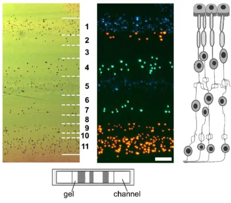
Fig. 2 Section of a microflui-dically structured microgel with fluorescent beads, in top view as brightfield (left) and fluores-cence (middle) images (solid lines mark gel–fluid boundaries, hatched lines are boundaries between gel stripes; the bar is 50μm). The cross-sectional view of the gel slab in a microchannel is sketched below. Such microengineered gels could serve as models for natu-ral tissues, e.g. the retina, the hierarchical structure of which is depicted on the right
molecules pass. Cells can, moreover, be released by dissolving the gel, a typical feature of contactless immo-bilization. This was recently demonstrated by us with cells entrapped in a calcium alginate hydrogel on a chip [17]. The extent to which dissociated polymer chains rest on the surface of the released cell has not been examined, however. An advantage of this type of cell entrapment is that no continuing action of an electromagnetic field is required to keep the cells in a defined distribution in space. This has recently been utilized by combining laser tweezing and the gel-encapsulation method. Several cells were first arranged in three dimensions by means of optical tweezers and the cell positions were then fixed in a gel [11]. Cell immobilization in gels is becoming increasingly important as a way of creating artificial tissues. Efforts are being undertaken to mimic living tissue function by equipping the gel with immobilized cell factors that resemble the natural extracellular matrix and that interact with the cells to regulate essential functions such as cell proliferation or differentiation. An important application of such systems would be long-term biosensors for determin-ing the effect of pharmaceuticals on the human organism. Microfluidic systems would enable high-throughput pro-cessing, reducing operation time and substance costs. Another aspect, besides creating the right environment for cells, is to reproduce the architecture of natural tissues on which proper tissue function is based. Because of the high-resolution feature sizes producible, microfabrication tech-niques are predestined for application in this field. Technologies enabling the creation of cell-loaded micro-gels of different internal structure, serving as small tissue samples, are therefore of high interest [18]. Figure2shows an example of a patterned alginate gel prepared by us in a microfluidic chip. Using calcium alginate gel has the advantage that polymerization and cell immobilization occur under mild conditions at room temperature. The gel, which is confined by fluid flows below and above, is
composed of alternating stripes with different fluorescent beads. For comparison a sketch of the layered structure of the retina is shown to illustrate a perspective of future development.
References
1. Lidstrom ME, Meldrum DR (2003) Nat Rev Microbiol 1: 158–164
2. Juncker D, Schmid H, Delamarche E (2005) Nat Mater 4: 622–628
3. Anderson DG, Levenberg S, Langer R (2004) Nat Biotechnol 22:863–866
4. Khademhosseini A, Yeh J, Eng G, Karp J, Kaji H, Borenstein J, Farokhzad OC, Langer R (2005) Lab Chip 5:1380–1386 5. Di Carlo D, Aghdam N, Hung PJ, Lee LP (2005) Proc
μTAS:379–81
6. Voldman J, Gray ML, Toner M, Schmidt MA (2002) Anal Chem 74:3984–3990
7. Holmes D, Green NG, Morgan H (2003) IEEE Eng Med Biol Mag 22:85–90
8. Chou CF, Zenhausern F (2003) IEEE Eng Med Biol Mag 22:62–67
9. Applegate Jr RW, Squier J, Vestad T, Oakey J, Marr DWM (2004) Opt Express 12:4390–4398
10. Ozkan M, Wang M, Ozkan C, Flynn R, Birkbeck A, Esener S (2003) Biomed Microdevices 5:61–67
11. Jordan P, Leach J, Padgett M, Blackburn P, Isaacs N, Goksör M, Hanstorp D, Wright A, Girkin J, Cooper J (2005) Lab Chip 5:1224–1228
12. Wiklund M, Spégel P, Nilsson S, Hertz HM (2003) Ultrasonics 41:329–333
13. Lilliehorn T, Simu U, Nilsson M, Almqvist M, Stepinski T, Laurell T, Nilsson J, Johansson S (2005) Ultrasonics 43: 293–303
14. Hertz HM (1995) J Appl Phys 78:4845–4849
15. Kimura T, Sato Y, Kimura F, Iwasaka M, Ueno S (2005) Langmuir 21:830–832
16. Chiou PY, Ohta AT, Wu MC (2005) Nature 436:370–372 17. Braschler T, Johann R, Heule M, Metref L, Renaud P (2005)
Lab Chip 5:553–559
18. Albrecht DR, Tsang VL, Sah RL, Bhatia SN (2005) Lab Chip 5:111–118