HAL Id: insu-02267563
https://hal-insu.archives-ouvertes.fr/insu-02267563
Submitted on 19 Aug 2019
HAL is a multi-disciplinary open access
archive for the deposit and dissemination of sci-entific research documents, whether they are pub-lished or not. The documents may come from teaching and research institutions in France or abroad, or from public or private research centers.
L’archive ouverte pluridisciplinaire HAL, est destinée au dépôt et à la diffusion de documents scientifiques de niveau recherche, publiés ou non, émanant des établissements d’enseignement et de recherche français ou étrangers, des laboratoires publics ou privés.
To cite this version:
Claudie Hulin, Lionel Mercury. Regeneration of capillary water in unsaturated zones. Geochimica et Cosmochimica Acta, Elsevier, 2019, 265, pp.279-291. �10.1016/j.gca.2019.07.058�. �insu-02267563�
Regeneration of capillary water in unsaturated zones Claudie Hulin, Lionel Mercury
PII: S0016-7037(19)30495-8
DOI: https://doi.org/10.1016/j.gca.2019.07.058
Reference: GCA 11378
To appear in: Geochimica et Cosmochimica Acta
Received Date: 17 April 2019
Revised Date: 31 July 2019
Accepted Date: 31 July 2019
Please cite this article as: Hulin, C., Mercury, L., Regeneration of capillary water in unsaturated zones, Geochimica
et Cosmochimica Acta (2019), doi: https://doi.org/10.1016/j.gca.2019.07.058
This is a PDF file of an article that has undergone enhancements after acceptance, such as the addition of a cover page and metadata, and formatting for readability, but it is not yet the definitive version of record. This version will undergo additional copyediting, typesetting and review before it is published in its final form, but we are providing this version to give early visibility of the article. Please note that, during the production process, errors may be discovered which could affect the content, and all legal disclaimers that apply to the journal pertain.
JOURNAL
PRE-PROOF
Regeneration of capillary water in unsaturated zones
Claudie Hulin* and Lionel Mercury
Institut des Sciences de la Terre d’Orléans, UMR 7327 Université d’Orléans / CNRS /BRGM, 1A rue de la Férollerie, 45071 Orléans cedex (France).
* Corresponding author: claudie.hulin@cnrs-orleans.fr
JOURNAL
PRE-PROOF
Abstract.
In porous media subject to drying conditions such as arid regions and excavation zones (deep gas injection or nuclear waste disposal), capillarity is involved in weathering processes because it modifies the geochemical and poromechanical balances within the porous network. Heterogeneous porous media like sedimentary rocks can host significant volumes of tensile capillary water in large pore bodies, and the negative pressure within is controlled by capillary forces exerted at nanometric pore throats.
We have developed experiments using synthetic bimodal pore systems conducive to capillary tension. In microtubes, salts precipitated in an evaporating solution to build a dual-porosity system. A large volume (ø 200 µm) became trapped behind nanometric pores, where high capillary tension was applied. We investigated the gas-water interactions there, especially how gas nucleated in the trapped liquid and how it subsequently changed size. After gas nucleation, the decreasing of gas volume that we observed has been attributed to two complementary geochemical effects. On the one hand, the water’s tensile state increases gas solubility, as predicted by thermodynamics: capillarity is a “gas-in” process. On the other hand, while the total volume of the gas-water assemblage remains constant, the water’s molar volume increases by capillary forces. Consequently, capillary forces exerted at the nano-throats can (re)induce a superheated monophasic liquid state from a biphasic liquid-gas assemblage even after gas nucleation. Tensions required for gas shrinkage have been estimated at 7 ± 3 MPa and 53 ± 15 MPa. This regeneration process offers opportunities for water to regularly return to a capillary state, making the capillary lifetime less limited than expected.
This shows that pore heterogeneity in rocks submitted to drying processes results in tension for water in pores that is long-lived. As a consequence, capillarity may significantly impact the long-term geochemical budget through its effects on gas and solid solubility and/or poromechanics (compaction, tensile stress, fracturing, etc.), so that it may play an important role in the weathering of drying porous materials.
JOURNAL
PRE-PROOF
1. INTRODUCTION
Capillary water is present in porous soils, rocks, and building materials exposed to the atmosphere. Above groundwater, the unsaturated zone (UZ) is characterized by the coexistence of air and water, and its behavior is controlled by evaporation and capillary forces. During drying periods, pore water is out of equilibrium with gases and host minerals, making the UZ particularly reactive and sensitive to weathering. Water either evaporates or is retained in the thinnest pores by capillary forces against gravity and evaporation. As the air becomes drier, capillary water is retained in increasingly thinner pores. The smaller the pores, the more the internal liquid pressure controlled by Kelvin equilibrium with vapor-undersaturated air decreases. In nanometric pores, capillary forces are so strong that water reaches significant negative pressure. This result is given by the Young-Laplace equation, which relates the difference of pressure across a liquid-air interface to its curvature. The capillary tensile stress has been shown to deform crystalline nano-channels (Tas et al., 2003) and soft porous materials (Bouzid et al., 2011a), and has been described as being responsible for cracks in concrete and cementitious materials (e.g., Ansell, 2010; Lagier et al., 2011; Li and Li, 2014). From a chemical point of view, thermodynamics states that the solubility of solids and gases increases if the water’s pressure decreases. (Mercury and Tardy, 1997a, b; 2001; Mercury et al., 2003; 2004; Lassin et al., 2005). Recent experimental studies agree for CO2 (Lassin et al., 2016) and O2 (Lidon et al., 2018) gases and
for salts (Hulin and Mercury, 2019).
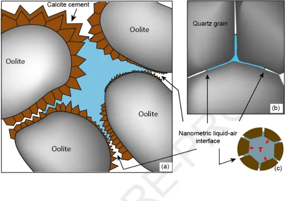
Capillary water under tension is not restricted to nanometric pores. Multiscale porous networks retain larger volumes of tensile capillary water, especially if large pores are connected through nanometric pores (Fig. 1). In such a network, during evaporation, pockets of water become isolated because they are surrounded by small pores from which water does not evaporate. The nanometric liquid-air interfaces generate high capillary forces that are transmitted to the macrovolume of hydraulically connected water (outer pore throats and inner pore bodies). This situation can arise in sedimentary rocks (Fig. 1a), (e.g., Muller and McCauley, 1992; Wang et al., 2003; Anovitz et al., 2013; Wang, 2014) or in crustal rocks (Fig. 1b).
JOURNAL
PRE-PROOF
Figure 1. Dual-porosity systems. (a) in oolitic sedimentary rocks, (b) in crustal settings. (c) corresponding schematic view of a filled macropore surrounded by nano-throats (solid in brown, liquid in blue).The large trapped volumes of hydraulically connected water under tensile state are actually metastable with respect to their vapor, corresponding to a superheated state. A gas bubble can nucleate at any time to restore the most stable state (water-vapor assemblage or vapor). However, gas nucleation is delayed because of the activation energy required to create the new liquid-air interface. Water can be brought to a superheated state in different ways, for example in closed cavities like Berthelot tubes (e.g., Berthelot, 1850) or fluid inclusions that are closed systems (e.g., Green et al., 1990). Within those closed cavities, low density water can be superheated using heating and isochoric cooling. According to previous studies on fluid inclusions (e.g., Takahashi et al., 2002; El Mekki et al., 2010, Shmulovich et al., 2009) and capillary systems (Bouzid et al., 2011b; Hulin and Mercury, 2019), the superheated lifetime can be of the order of months, even years, and is probably linked to the water volume (e.g., Skripov, 1992; Imre et al., 1998; Takahashi et al., 2002; Shmulovich and Mercury, 2014). In capillary systems, the superheated tensile state in the macrovolume lasts long enough for salt
JOURNAL
PRE-PROOF
to dissolve and reach equilibrium with tensile water, showing how capillarity impacts the geochemical balance (Hulin and Mercury, 2019).
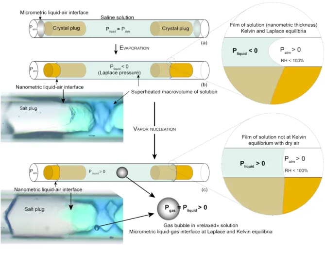
In this work, we performed a series of experiments to study the behavior of water-gas interactions in a macrovolume of water under capillary tension. Gas nucleated as already observed (Hulin and Mercury, 2019) that relaxed the tensile superheated state of water. As the system is open to dry air, there are two interfaces: the pre-existent nanometric interface in the pore throat (water-external air) and the new micrometric interface in the macrovolume (water-gas bubble). The question raised about the gas equilibrium across both interfaces. Are the capillary forces still generated by the nanometric interface after nucleation despite the presence of the micrometric bubble? To address this issue, we studied the behavior of the gas bubble after its nucleation and discussed the observation assisted by thermodynamic calculations, considering that the system reached a new equilibrium driven by the capillary forces. The principle of the experiments was to build heterogeneous pore systems modeled on heterogeneous natural poral networks (Fig. 1) from monosized microtubes. These bimodal pore systems already described (Hulin and Mercury 2019) lead to capillary tension. Cylindrical microtubes were filled with a saline solution that evaporated under drying conditions. Salts precipitated on both air–liquid interfaces at the highest salt concentration and grew until a cylinder formed (Fig. 2a). Water evaporated and a thin nanometric film persisted between the crystal and the glass wall (Fig. 2b). This produced a bimodal water-filled pore system combining an inner large pore body at the scale of 100s of microns and outer nanometric pores. This geometry leads to high capillary conditions because of the strongly contrasted pore size. Capillary forces prevent evaporation at the nano-throat liquid-air interface and generate negative pressure in the entire trapped solution. Within the macrovolume, the water under tension is in a superheated state (Fig. 2b). This is supported by the final bubble nucleating inside the trapped macrovolume (Fig. 2c). After nucleation, the liquid internal pressure in the macrovolume returns to a positive value and should not be at Kelvin equilibrium with dry air, so the nanometric interface should become flat and evaporation should start (Fig. 2c). Our “double plug” systems are illustrated below (Fig. 2, schemes and pictures). We used blue inert dye dissolved in water to visualize the nanometric film and interface along the plug, but this does not provide quantitative results (Fig. 2).
JOURNAL
PRE-PROOF
Figure 2. Main experimental steps modified from Bouzid et al., 2011b and Hulin and Mercury, 2019 (see text). Step (a): salt precipitation and evaporation. Step (b): nanometric air-water meniscus obeying the Young-Laplace law (closer view) and confined metastable macrovolume. Step (c): thermodynamic conditions after gas nucleation, by assuming an equilibrium situation between bubble and relaxed liquid and a non-equilibrium situation at nanometric water-air interface after gas nucleation.2. MATERIAL AND METHODS
2.1 Materials
In this study, experiments were carried out in 200 µm diameter cylindrical and 400x400 µm square capillaries made of borosilicate glass from VitroCom (VitroTubesTM). NaCl and Na
2SO4 aqueous
solutions were prepared from NormaPur powder (Prolabo) and distilled water. The NaCl solution was at 5.5 mol.L-1 (24.3 wt. %) and had relative supersaturation of n/n
0 = 0.90 (molality at saturation n0 =
6.15 mol.L-1 at 20°C). The Na
JOURNAL
PRE-PROOF
respect to thenardite (relative supersaturation n/n0 = 0.64 at 20°C) and supersaturated with respect to
mirabilite (relative supersaturation n/n0 = 1.19 at 20°C). The saline solutions were filtered with 0.450
µm filters (VWR® syringe filters) to avoid impurities and micro-crystallites. This means that there were no or very few potential seeds in the solution, so that during evaporation, the solution would reach high supersaturation before crystals nucleated (Desarnaud et al., 2014).
The evaporative demand, leading to evaporation or capillary conditions, was set by controlled relative humidity (RH) in a climate chamber (HPP108, Memmert technology). The preferred RH was 48%, to be compared with the equilibrium RH of a saturated NaCl solution (75.3%, Greenspan, 1977) or of a Na2SO4 solution (93%, Winston and Bates, 1960). This RH gradient enabled a moderate drying
rate, promoting the precipitation of massive salt (Desarnaud et al., 2014) when the appropriate supersaturation was reached, at constant temperature. The microcapillaries were regularly observed using an optical microscope (Leica DM2500) in a room thermostated at 20°C. Observations were made in transmitted light using lens with 5x, 10x, 20x and 50x magnification. Pictures were captured with a Leica DFC295 digital camera allowing image resolution of 3 megapixels (2048 x 1536) and pixel size of 1.2 µm x 1.2 µm with a 5x magnification lens. To avoid any heat transfer, we reduced exposure to microscope lights to the minimum possible, so we can consider that the heating due to light was negligible.
2.2 Methods
Bimodal systems were built with halite from supersaturated NaCl solution and thenardite with supersaturated Na2SO4 solution with respect to mirabilite. Using plasma cleaned tubes (15 min), halite
nucleated and grew rapidly with a symmetric hopper (skeletal) shape (Sunagawa, 1999; Desarnaud et al., 2014), (Fig. 3Aa). Several cubes crystallized on each other with growth parallel to the tube and toward the tube opening (Fig. 3Aa, b). Halite continued to grow on each side and not at the middle because at this point the solution was trapped and did not evaporate, explaining the “bow-tie” shape (Fig. 3Ab, c). The solution on each external side of both salts (outer side of the tube) continued to evaporate until reaching first the external edge of one salt (Fig. 3Ac), and then reaching the external
JOURNAL
PRE-PROOF
edge of the other salt (Fig. 3Ad). At this point, the liquid-air interface no longer receded because no air entered in the trapped solution. We built 26 of these systems.
In the other tubes, two distinct salts (halite or thenardite) precipitated on both air–liquid interfaces at the highest salt concentration, trapping a large volume of aqueous solution. We built 22 of these systems: 12 with halite and ten with thenardite. More details about the experimental procedure are given in Hulin and Mercury (2019).
Figure 3. Double-plug systems. (A) crystallization sequence to build “bow-tie shape” system with halite (see text). (B) and (C) double-plug systems built with halite (B) and thenardite (C) entrapping a large volume of solution.
JOURNAL
PRE-PROOF
3. RESULTS
The double-plug systems were built in 48 tubes. In each tube, the drying conditions caused the liquid-air interface to recede until reaching the external side of a crystal. We never observed any air entry in the trapped macrovolume, meaning that the liquid-air interface remained in the narrow space between the salt and the tube wall and no longer evaporated. After one external side of one crystal was dried and only after (Fig. 3Ac), we observed different reactions in the trapped volume: salt dissolution, solid displacement (Hulin and Mercury, 2019) and gas nucleation. For up to 2 years, we carefully monitored (up to 2 years) the subsequent behavior of the bubble. Results are summarized in Table 1.
Number No gas nucleation Gas Time before Gas bubble evolution Exp type of exp No change Salt motion nucleation gas nucleation No change Partial contraction Disappearance
NaCl 37 11 2 25 2 days to 3 months 21 1 3
Na2SO4 10 0 10 20 days to 3 months 5 fluctuation)4 (size 1
Total 48 11 2 35 - 26 5 4
Table 1. Summary of dual porosity systems and major observables.
3.1 Nucleation of gas bubble
We observed the formation of a gas bubble in the trapped solution in 35 of the 48 bimodal systems. Bubbles appeared typically after at least one of the crystal plugs was dry, after from several days to months, This gas nucleation had been previously reported and is not the result of air entry (Bouzid et al., 2011b; Hulin and Mercury, 2019). Figure 4 illustrates two experiments in which gas nucleated in the trapped solution. In the first experiment, with bow-tie halite, (Fig. 4A), gas nucleated 10 days after both external sides of the crystal dried (Fig. 4Ac). In the second experiment, with thenardite (Fig. 4B), gas nucleated two months after both external sides of both crystals had dried. In the latter case, gas nucleated in the middle of the solution far away from the crystals (Fig. 4B).
In the 13 other tubes, no gas nucleation has been observed after 2 years. Eleven of the 13 tubes did not evolve at all as if the systems were chemically and mechanically inert over the experimental time. The remaining two tubes did show a small inward displacement of the crystal plugs, without bubble nucleation within the experimental time (Table 1).
JOURNAL
PRE-PROOF
Figure 4. Gas nucleation in the trapped solution: (A) in a NaCl solution trapped by a halite crystal, (B) in a Na2SO4solution trapped by two thenardite crystals. See text.
3.2 Bubble shrinkage
After gas nucleated, 26 of the 35 systems did not evolve. The bubble did not grow, meaning that the solution did not evaporate. In the remaining nine systems (four built with halite and five built with thenardite), not only did the liquid not evaporate, but the bubble shrank and completely disappeared within four of the nine tubes (three in NaCl systems, one in a Na2SO4 systems, see Table 1). In the
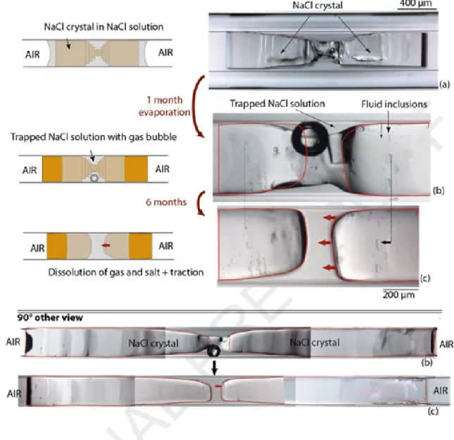
experiment shown in Figure 5, the shrinkage of the bubble was accompanied by inward movement of the crystal plugs and partial salt dissolution. Fluid inclusions visible on the halite surface (Fig. 5b, c) acted as markers to indicate that the two crystals got closer. The bubble had an initial size of 2.1×10⁻³
JOURNAL
PRE-PROOF
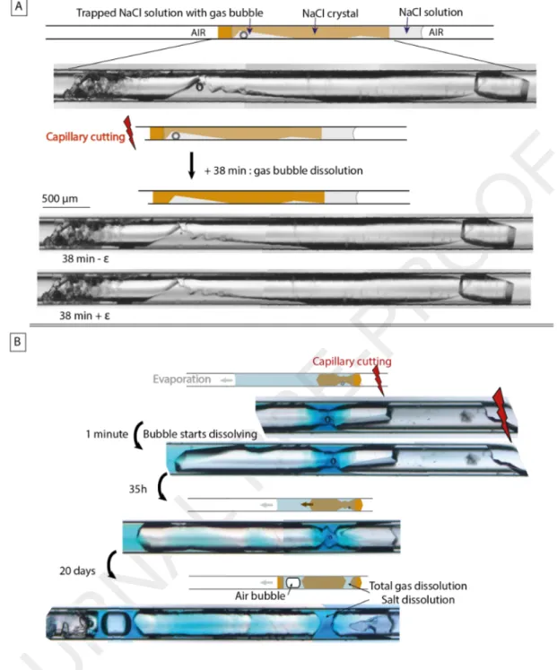
Figure 5. Shrinkage of gas bubble trapped in the solution associated with salt dissolution and salt inward traction (fluid inclusions in halite act as markers). Step (a): growth of bow-tie halite crystal. Step (b): gas nucleation in the trapped solution after the both external sides of salt dried. Step (c) gas shrinkage, salt dissolution and salt inward traction (see also the 90° other view).In two other experiments made with bow-tie shape halite, gas nucleated in the trapped solution after one external side of the crystal dried. The dry side of the crystal was far from the tube opening, and we cut the tube close to it (Fig. 6). A few minutes after cutting the tube, the gas bubble began to shrink and then finally disappeared. In the first experiment, it took 38 minutes for the bubble to shrunk and disappear (Fig. 6A). In the second experiment (Fig. 6B), the bubble shrank rapidly initially, but then persisted for 20 days. As in the Figure 5 experiment, bubble shrinkage was associated with salt dissolution.
JOURNAL
PRE-PROOF
Figure 6. Disappearance of gas bubble after cutting the tube.3.3 Bubble size cycling
Our final situation (Fig. 7) is representative of what we observed in double-plug systems built with Na2SO4 crystals (thenardite). In these systems, we did not observe salt dissolution or traction but often
bubble contractions and size fluctuations. In five of the ten systems built with thenardite, the bubble shrank (Fig. 7b-c) and each time the bubble size fluctuated with different periods ranging from hours to months (Fig. b-e). Sometimes the size fluctuation was visible in real time as if the bubble was
JOURNAL
PRE-PROOF
breathing. In one experiment (Fig. 7), the fluctuation period ultimately finished with complete disappearance of the bubble (Fig. 7f). Two days after the gas disappeared, gas nucleated again in the trapped solution (Fig. 7g) and the cycle resumed.
Figure 7. Partial contraction of a gas bubble in a double plug Na2SO4 system until complete disappearance. Step (a):
The two external sides of the two salts are dry. Step (b): gas nucleated in the trapped solution after 1 month. Step (c): gas bubble shrank until almost disappearing after 1 month. Step (d): bubble grew again. Step (e): bubble shrank again until disappearing. Step (f): gas nucleated in the middle of the trapped solution after 2 days.
4. DISCUSSION
4.1 Tensile state, metastability and vapor nucleation
Gas nucleation is assumed to result from the water cavitation in a superheated liquid. “Cavitation’’ is the term commonly used for rapid vapor nucleation happening in superheated water (Reid, 1983; Skripov, 1992; Imre, 1998; Kiselev and Ely, 2001). Before that, the trapped solution was brought under tensile state by capillary forces generated by the curved nanometric liquid-air interface. This implies the existence of a capillary film along a nano-scale space between the solid plugs and the tube
JOURNAL
PRE-PROOF
walls. The curvature of the nanometric air-liquid interface (concave toward the air) compensates for the pressure drop through this interface, which is due to a decrease of the liquid pressure. According to the Young-Laplace law, the liquid pressure decreases as the interface’s curvature increases, until reaching negative values for nanometric curvature radii.
The thermodynamic driving force towards capillarity comes from the air’s relative humidity when below the saturated vapor pressure:
ln 𝑃 𝑃𝑠= 𝑅𝐻 100= 1 𝑅𝑇 𝑃𝑐𝑎𝑝
∫
𝑃0 𝑉𝑤𝑑𝑃 + 𝑙𝑛𝑎𝑤 (1) Where p, pS are respectively the new vapor pressure (curved concave interface, Pliquid < Pair) and theinitial saturated vapor pressure (plane interface, Pliquid = Pair), RH is the relative humidity, Pcap is the
liquid pressure in capillary conditions, VW the molar volume of pure water, and aW the water activity
controlled by the chemical composition (osmotic effect). At a given air relative humidity below the brine equilibrium RH (75.3% for NaCl, Greenspan, 1977; 93% for Na2SO4, Winston and Bates, 1960),
there is an air-water curvature that makes the capillary liquid be at equilibrium with the undersaturated air. Consequently, the liquid is at equilibrium with the dry air and does not evaporate any more. In nano-throats, the thickness is too small for the vapor nucleus to reach the critical radius required for vapor nucleation and the water film is at equilibrium. In contrast, the connected macrovolume of solution is at the same negative pressure but trapped within a much larger space than the critical radius. Consequently, there is no barrier toward gas nucleation. The stretched water is metastable with respect to its vapor and is prone to boil at any time. The same stretched superheated state of water can be found in closed micrometric cavities like fluid inclusions or Berthelot tubes. The difference is that in this case, water is brought into the superheated state not by capillary forces at constant temperature but by heating and isochoric cooling (e.g., Roedder, 1967; Alvarenga et al., 1993; Caupin and Herbert, 2006; Shmulovich et al., 2009; Qiu et al., 2016).
The lifetime of a superheated state is variable, consistent with classical nucleation theory (CNT): activation energy is required to overcome the energy barrier and create the liquid-vapor interface. According to CNT, the lifetime decreases if the superheated degree and therefore the liquid tension
JOURNAL
PRE-PROOF
increases (i.e., the P-T conditions are far below the saturation curve, Fig. 8). In addition, the presence of impurities and wall roughness favor heterogeneous gas nucleation and so decrease the lifetime of the tensile state. Experimental studies have shown that the superheated lifetime can be of the order of months, even years, in fluid inclusion (El Mekki et al., 2010, Shmulovich et al., 2009) and in capillary systems (Bouzid et al., 2011b; Hulin and Mercury, 2019). In our experiments, we observed vapor nucleation in 35 of 48 microtubes after a superheating period ranging from a few days to years.
Gas nucleation results in superheated water returning to its most stable state, either the gas state or a liquid-gas assemblage depending on thermodynamic conditions. In our experiments we observed the formation of a liquid-gas assemblage. This coexistence implies that liquid and gas are at chemical equilibrium (their water’s chemical potentials are equal) and at mechanical equilibrium. Liquid and vapor should have the same pressure since the large curvature radius cannot compensate for a pressure drop across their interface. After gas nucleation, there are two liquid-gas interfaces: the pre-existing nanometric interface in the pore throat (water-external air) and the new water-gas bubble interface with a micrometric curvature. The presence of the two interfaces indeed implies a non-equilibrium situation. The liquid water cannot be at equilibrium with both the liquid-gas bubble at vapor saturation and the dry air through the nanometric liquid-air interface (Kelvin’s Law). The former drives water to be evaporated through the nanometric interface while the latter drives a pressure drop in the liquid that stops the evaporation. This implies a difference of pressure across the bubble-liquid interface that cannot be mechanically compensated because the bubble is micrometric.
JOURNAL
PRE-PROOF
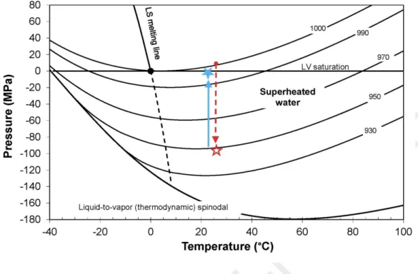
Figure 8. Phase diagram of pure water, calculated using the IAPWS-95 equation of state (Wagner and Pruss, 2002). The red dashed arrow shows the pathway of a liquid brought into the tensile domain (red empty star) at constant temperature. As vapor nucleates, liquid can return to the saturation curve if the total volume and temperature are constant (blue solid arrow and blue filled star). Solid curves (excepting the LV saturation line) represent the isochores and numbers give the corresponding density of water (kg.m-3).The P-T phase diagram of pure water extended to the superheated state helps to represent the conceptual thermodynamic pathways in the tubes (Fig. 8). The red arrow shows the pathway at 25°C when the pressure decreases in the trapped liquid from atmospheric pressure to high negative pressure (empty red star) by capillary forces. Lines of constant density (solid lines) allow us to estimate the density drop (and therefore, the volume increase) as the liquid pressure decreases toward negative values (empty red star). Using the equation of state of pure water (Wagner and Pruss, 2002), the density of water decreases from 997 to 963 kg.m3 when the pressure decreases from the LV saturation
vapor pressure (31.7 mbar) to -700 bars, corresponding to an increase in volume by +0.64 cm3.mol-1.
The liquid remains under tensile and superheated state for a certain amount of time before vapor nucleation that brings the system to a liquid-vapor assemblage. The corresponding pathway in the P-T phase diagram of water is represented by the blue arrow (Fig. 8) from high negative pressure to saturated vapor pressure (Fig. 8, on the saturation curve, filled blue star). This thermodynamic trajectory is correct as long as the total volume and the temperature are constant.
JOURNAL
PRE-PROOF
4.2 Non-equilibrium situation and bubble contraction
Water cavitation is irreversible in the sense that energy would be provided to restore its previous metastable state. There is a way to induce superheating from a liquid-vapor assemblage in closed systems like Berthelot tubes (e.g., Berthelot, 1850) and fluid inclusions (e.g., Roedder, 1967). The system is heated until the liquid homogenizes and is cooled down isochorally without vapor nucleation. In contrast, our system is open to dry air through the nanometric liquid-air interfaces and temperature is constant. After gas nucleation, there are two liquid-gas interfaces that cannot be at equilibrium in the same time, implying a non-equilibrium situation. To simplify, two extreme situations can be envisaged leading to different ways the system can evolve: (1) if the gas bubble is at equilibrium with trapped water, the latter is at positive pressure and cannot be at equilibrium with dry external air. If so, liquid should evaporate. (2) If water is in equilibrium with dry air, it must be at negative pressure, which can be compensated mechanically by the nanometric curvature of the interface. In this case, tensile water cannot be at equilibrium with the micrometric gas bubble. As we did not observe any water evaporation in our systems (the bubble has never expanded), the first non-equilibrium situation is rejected. The contraction and disappearance of the bubble (Figs. 5-7) is in line with the second situation, which implies that capillary forces are still exerted at the nanometric interface in spite of the presence of a gas bubble.
Moreover, the total contraction of the gas bubble (Figs 5-7) restored a monophasic liquid state, making it possible to induce a tensile superheated state again in the trapped liquid and possibly establish the same tension as before gas nucleation. Evidence of this regeneration is that the gas renucleated after it disappeared (Fig. 7f to g), showing that the liquid had returned to a tensile superheated state. The driving forces toward homogenization are related to capillarity, since temperature, total volume and composition remain constant. This assumption is supported by the two experiments where we cut the tube close to the dry salt plug (Fig. 6). Before cutting, the salt plug and the nanometric liquid-air interface were far from the tube opening and from the dry air (around 3 cm). Thus, the inner relative humidity should have been high and capillary forces should have remained weak. By cutting the tube, the local relative humidity decreased, driving enhanced capillary forces in
JOURNAL
PRE-PROOF
the trapped liquid. In the second experiment (fig. 6B), bubble disappearance was associated with salt dissolution, which is in line with a tensile state in the liquid solution, according to thermodynamics (Mercury and Tardy, 1997a, b; 2001; Mercury et al., 2003) and observations (Hulin and Mercury, 2019).
4.3 Estimation of tension
The contraction of the gas bubble corresponds to reducing the gas volume. Two effects must be taken into account: (1) the change in the molar volume as water expands and (2) gas dissolution due to increased gas solubility in tensile water. (1) The molar water volume is increasing under tension (e.g., Mercury et al., 2003), (Fig. 9). For instance, the volume increases by 0.2 cm3.mol-1 in water at -25
MPa or by 1 cm3.mol-1 in water at -100 MPa (Mercury and Tardy, 1997a, 2001). At constant total
volume, this shrinks the bubble and makes it size-decreasing.
18,0 18,2 18,4 18,6 18,8 19,0 -100 -80 -60 -40 -20 0 M o la r vo lu m e (c m 3/m o l)
Water pressure (MPa)
Figure 9. Molar volume of liquid water predicted by extrapolating the IAPWS-95 equation of state (Wagner and Pruss, 2002) at negative pressure and 21°C.
The capillary pressure is also a thermodynamic parameter involved in any reactional Gibbs free energy calculations. The gas solubility at constant gas pressure (open system) is classically written:
ln𝐾𝐻(𝑃𝑐𝑎𝑝) 𝐾𝐻 (𝑃0) =‒ 𝑃𝑐𝑎𝑝
∫
𝑃0 𝑉𝑑𝑖𝑠𝑠𝑜𝑙𝑣𝑒𝑑 𝑔𝑎𝑠 𝑑𝑃 𝑅𝑇 (2)JOURNAL
PRE-PROOF
One such assumption of such a calculation is that the pressure of each dissolved solute is equal to the pressure of liquid solvent, which is clearly a simplification (e.g., Mercury et al., 2016). The pressure dependency of ion volumes at infinite dilution are taken from Tanger and Helgeson (1988), and the pressure effect on the activity coefficient is overlooked, which does not afford a significant error (e.g., Lassin et al., 2005). The complete calculation for common gases shows the same trend towards increasing solubility (Fig. 10) as a function of their molar masses. At -100 MPa compared to bulk water, the solubility is multiplied by two for water vapor or by five for methane.
1,0 1,5 2,0 2,5 3,0 3,5 4,0 4,5 5,0 -100 -90 -80 -70 -60 -50 -40 -30 -20 -10 0 KH (1 ) / K H (P ) at 2 5° C
Water pressure (MPa)
Nitrogen Oxygen Carbonic gas
Methane Water vapor
Figure 10. Ratio between Henry’s law constant for various gases in tensile water compared to normal water at 21°C, which directly expresses the activity ratio in solution (solubility).
The contraction of the bubble must results from the cooperation between the dissolution of gases in the solution and the compression of the bubble by the water expansion. The tension required to homogenize the system to liquid was calculated by numerical iteration combining these two effects. For our calculations, two assumptions were made. First, the bubble was assumed to have an atmospheric composition because the time after cavitation was long enough to equilibrate the gas bubble with the solution, which was originally at equilibrium with atmosphere. Using this hypothesis, the bubble is composed of 79% N2 and 21% O2, with a vapor pressure of 25 mbar (saturation pressure
at 21°C). Second, once the bubble disappeared, the system was considered to be at equilibrium. In two experiments (Figs 5 and 7), the tension could be estimated using the volume of liquid and bubble before its total contraction. In the first experiment (Fig. 7), the trapped liquid volume was measured
JOURNAL
PRE-PROOF
quite precisely because of the simple geometry of crystal plugs and liquid macrovolume. A gas bubble of 0.5x10⁻³ to 1.0x10⁻³ mm3 shrank in a volume of solution of 0.23 ± 0.10 mm3 (Fig. 7a to f). The
thermodynamic model predicted a required tension of 6.8 ± 2.3 MPa. This tension increases the solubility of thenardite (anhydrous Na2SO4) by 1 to 2%, which could explain the absence of visible
dissolution.
In the other experiment (Fig. 5), the uncertainty was greater because of the less accurate volumes of bubble and trapped liquid. We estimated them with a 3D model (Fig. 11). A gas bubble of 2.1×10⁻³ ±
0.5×10⁻³ mm3 shrank in a liquid volume of 80×10-3 ± 5×10⁻³ mm3. The calculated tension required for
the bubble to disappear ranged from 38.5 to 67.9 MPa. This tension increases the solubility of halite (NaCl) by 13 to 22%, explaining why the salt dissolves in the trapped solution as the bubble contracts. The tensile state was also supported by the inward traction of the two salt plugs (Fig. 5c).
Figure 11. Three-dimensional model of the bow-tie salt crystal shown in Figure 5, enabling precise calculation of trapped water volume.
4.4 Regeneration of superheated state by capillary forces – Mechanisms and implications in natural porous systems.
Bubble contraction is in line with the new chemical equilibrium imposed by the tensile water because of its higher gas solubility and its higher specific volume. The required energy is provided by
JOURNAL
PRE-PROOF
capillary forces exerted at the nano-throats. This is supported by the absence of evaporation - meaning that the liquid-air interface remains at Kelvin equilibrium - and even more by bubble contractions. However, the mechanism or mechanisms involved in the maintaining, the partial or the total contraction of bubbles remains an open issue. In all cases, we must assume that a gas bubble at positive pressure (in the macrovolume, as long as the liquid-gas assemblage exists) and a liquid under negative pressure (driven by capillarity at the nano-throats) coexist. Yet the whole volume of trapped water is hydraulically continuous, so the transmission of pressure should be instantaneous (Pascal’s Law).
This situation resonates with the problem of refilling tree xylems after embolization (Cochard et al., 2009; Delzon et al., 2010). The cohesion-tension theory states that the main force that governs the ascent of crude sap in tree xylems is the negative pressure, driven by nano-menisci located in leaves (e.g., Cochard et al., 2009; Zimmerman, 1983). After a gas nucleation due to a period of drought, capillary forces could help to restore hydraulic continuity in xylems, in addition to biological factors.
To explain the liquid-gas coexistence, we must consider a transient non-equilibrium situation: a non-equilibrium in the liquid itself (anisobaric liquid), a non-equilibrium across the bubble interface, and possibly across the nanometric interface. This situation can last for days, months, or even years where the bubble either does not move (27 cases), partially shrank (four cases), or totally shrank (four cases). The Na2SO4 filled experiments (Fig. 7) where the bubble volume fluctuated with various
periodicities illustrate that there may be a competition between the capillary forces imposing liquid tension and the gas bubble imposing positive pressure. The system either evolves toward a state dominated by positive pressure (a big bubble) or toward a state dominated by capillarity that makes the gas bubble shrink and possibly disappear. If the latter, the system can return to a metastable monophasic (liquid) state, inevitably prone to vapor cavitation, before the bubble contracts again, possibly continuing the cycle. These varying pathways may be determined by several subtle factors, such as phase volume ratio, tension values, or even the rate of growing tension. As an example, there may be a critical gas/liquid volume ratio beyond which reversibility is not possible, in analogy with the hydraulic point of no return in trees (Meinzer and McCulloh, 2013).
JOURNAL
PRE-PROOF
During this period of instability, we were not able to measure the curvature of the meniscus because of its nanometric size. Being able to do that would clarify what happened at the nanometric interface. The curvature is controlled by the local RH and the ability of water to decrease its pressure (the water’s pressure is also constrained by the bubble’s pressure). All we know is that the RH did not change outside the tube (48%), while the RH at the nanometric interface is not precisely known, as illustrated by the cutting experiments (Fig. 6). The liquid was able to return to a superheated tensile state (monophasic liquid, figs 5c; 6A, B; 7f) before (re)cavitation (Fig. 7g), and the cycle could start again. The reversibility of the superheated state did not appear as a rare event in our experiments, which suggests that this phenomenon could be frequent and significant in drying porous media. This also supports the non-equilibrium model, despite a problematic long non-equilibrium period.
Porous media are often subject to dryness, and not only the exposed rocks and soils but also deep aquifers, which are exploited for various purposes, such as tunnel excavation, CO2 mitigation (e.g.,
Armand et al., 2013, 2014; Ott et al., 2014, 2015; André et al., 2014; Peysson et al., 2014; Tambach et al., 2015), and nuclear waste disposal (e.g., Vinsot et al., 2013; de la Vaissière et al., 2015). In terms of geochemistry, gas solubility increasing with capillary state could play a significant role on CO2
mitigation by enhancing its solubilization in the area of injection. Capillarity could also affect the geochemical budget in unsaturated zones subject to drying periods like arid and semi-arid zones (40% of the Earth’s surface). In terms of mechanics, tensile strength due to tension in the pore fluid may induce some fatigue effect and possibly fractures within pore walls (Hulin and Mercury, 2019).
5. CONCLUSIONS
These experiments show that capillarity has an effect on in-pore gas liquid interaction and are in line with previous measurements that demonstrated the supersolubility of gas in capillary water
JOURNAL
PRE-PROOF
(Lassin et al., 2016; Lidon et al., 2018). Those were conducted in nanoporous natural material; here we extend the gas supersolubility effect to larger pores in heterogeneous porous media.
After vapor nucleation in a superheated solution, the liquid was supposed to return to its more stable state, which would be a gas phase alone if all the liquid had evaporated. However, not only did the water never evaporate, but the gas bubble in some cases (nine in this study) shrank and even disappeared (four of the nine). Capillary forces can re-generate tensions of the same order of magnitude as the tension arising before gas nucleation. Tensions required for gas shrinkage have been estimated at 7 ± 3 MPa and 53 ± 15 MPa, in good agreement with the 36 ± 6 MPa and 78 ± 18 MPa ranges obtained in similar bimodal porous systems (Hulin and Mercury, 2019). We show here that strong capillarity can be re-loaded under certain conditions, probably driven by the nanometric interface. However, the mechanisms remain unclear, in particular regarding the pressure equilibria from nano- to macrovolumes during the size-decreasing period. Despite this lack of understanding, we know that this process is possible because the system is open to the exterior and subjected to external air (with humidity).
This is a completely new way, to the best of our knowledge, of promoting superheating in porous rocks from biphasic liquid-gas systems. However, further work is needed to clarify mechanisms that allow the coexistence between capillary forces existing at nano-throats with almost-flat liquid-air interfaces at gas bubbles.
Observations show that it is possible to induce capillary tension in large volumes of water, and that such tension modifies the geochemical and mechanical balance at the pore scale (Hulin and Mercury, 2019). The stretched liquid is metastable so has a limited lifetime. However, this limited lifetime can last several days, months or even years before vapor nucleation (Bouzid et al., 2011b; Hulin and Mercury, 2019). The regeneration of capillary conditions that we observed here makes it clear that this limited lifetime is compatible with long-term capillary conditions. The regeneration of the superheated state, like the first pressure decrease in the macrovolume, is driven by low RH, which is available once nano-throats are in contact with dry air.
The long-life superheated tensile state, coupled with the ability of capillary water to regenerate, means that capillarity has greater geochemical and mechanical effects than previously thought. The
JOURNAL
PRE-PROOF
expansion of arid and semi-arid zones and the rise of extreme events (e.g. Destouni and Verrot, 2014; Touhami et al., 2015; Wanders and Wada, 2015; Zhang and Zhou, 2015), the decrease of the water budget in unsaturated soils and the growing exploitation of deep aquifers may emphasize the effects of capillarity in water-rocks interactions and alterations at the global scale.
Acknowledgments.
We are grateful to Carl Steefel for handling the manuscript and for his helpful comments and suggestions. We also want to thank Karen McMillan (McMillan translation) for the language corrections and for helping us improving the text.
This work has received support from the French Agency for Research (Agence Nationale de la Recherche, ANR) through the CONGE BLAN-610-01 grant, the Equipex Planex ANR-11-EQPX-36 and Voltaire labex ANR-10-LABX-100-01.
REFERENCES
Alvarenga A.D., Grimsditch M., and Bodnar R.J. (1993) Elastic properties of water under negative pressures. J. Chem. Phys. 98 (11), 8392-8396.
André L., Peysson Y. and Azaroual M. (2014) Well injectivity during CO2 storage operations in deep
saline aquifers – Part 2: Numerical simulation of drying, salt deposit mechanisms and role of capillary forces. Int. J. Greenh. Gas Control 22, 301-312.
Anovitz L. M., Cole D. R., Rother G., Allard L. F., Jackson A. J., Littrell K.C. (2013) Diagenetic changes in macro- to nano-scale porosity in the St. Peter Sandstone: An (ultra) small angle neutron scattering and backscattered electron imaging analysis. Geochim. Cosmochim. Acta 102, 280-305. Ansell A. (2010) Investigation of shrinkage in shotcrete on tunnel drains. Tunn. Undergr. Sp. Tech. 25,
607-613.
Armand G, Noiret A., Zghondi J., Seyedi D.M. (2013) Short- and long-term behaviors of drifts in the Callovo-Oxfordian claystone at the Meuse/Haute-Marne Underground research Laboratory. J. Rock
JOURNAL
PRE-PROOF
Armand G., Leveau F., Nussbaum C., de La Vaissiere R., Noiret A., Jaeggi D., Landrein P., and Righini C. (2014) Excavation Induced Fractures at the Meuse Haute-Marne URL Drifts: Geometry and Properties. Rock Mech. and Rock Eng. 47, 21-41.
Berthelot M. (1850) Sur quelques phénomènes de dilatation forcée des liquides. Ann. Chim. Phys. 30, 232–237.
Bouzid M., Mercury M., Lassin A., Matray J.-M. and Azaroual M. (2011a) In-pore tensile stress by drying-induced capillary bridges inside porous materials. J. Colloid Interface Sci. 335, 494-502. Bouzid M., Mercury L., Lassin A. and Matray J.-M. (2011b) Salt precipitation and trapped liquid
cavitation in micrometric capillary tubes. J. Colloid Interface Sci. 360, 768-776. Caupin F. and Herbert E. (2006) Cavitation in water: a review. C.R. Phys. 6, 1000-1017.
Cochard H., Hölttä T., Herbette S., Delzon S., and Mencuccini M. (2009) New Insights into the Mechanisms of Water-Stress-Induced Cavitation in Conifers. Plant Physiol. 151, 949–954.
de la Vaissière R., Armand G., Talandier J. (2015) Gas and water flow in an excavation-induced fracture network around an underground drift: a case study for a radioactive waste repository in clay rock. J. Hydrol. 521, 141-156.
Delzon S., Douthe C., Sala A., and Cochard H. (2010) Mechanism of water-stress induced cavitation in conifers: bordered pit structure and function support the hypothesis of seal capillary-seeding.
Plant Cell Environ. 33, 2101–2111.
Desarnaud J., Derluyn H., Carmeliet J., Bonn D. and Shahidzadeh N. (2014) Metastability limit for the nucleation of NaCl crystals in confinement. J. Phys. Chem. Lett. 5, 890−895.
Destouni G. and Verrot L. (2014) Screening long-term variability and change of soil moisture in a changing climate. J. Hydrol. 516, 131-139.
El Mekki, M., Ramboz, C., Perdereau, L., Shmulovich, K., & Mercury, L. (2010) Lifetime of superheated water in a micrometric synthetic fluid inclusion. Metastable Systems under Pressure. Ed. Springer, Dordrecht, pp. 279-292.
Green J.L., Durben D.J., Wolf G.H. and Angell C.A. (1990) Water and solutions at negative pressure: Raman spectroscopic study to -80 Megapascals. Science 249, 649-652.
JOURNAL
PRE-PROOF
Greenspan L. (1977) Humidity Fixed Points of Binary Saturated Aqueous Solution. J. Research Nat.
Bur. Standards 81A 1, 89-96.
Hulin C. and Mercury L. (2019) Capillarity-driven supersolubility in dual-porosity systems. Geochim.
Cosmochim. Acta 252, 144-158.
Imre A., Martinas K. and Rebelo L. P. N. (1998) Thermodynamics of negative pressure in liquids. J.
Non-equilib. Thermodyn. 23 (4), 351-375.
Kiselev S. B. and Ely J. F. (2001) Curvature effect on the physical boundary of metastable states in liquids. Physica A 299, 357-370.
Lagier F., Jourdain X., De Sa C., Benboudjema F., Colliat J.B. (2011) Numerical strategies for prediction of drying cracks in heterogeneous materials: Comparison upon experimental results.
Engineering Struct. 33, 920–931.
Lassin A., Azaroual M and Mercury L. (2005) Geochemistry of unsaturated soil systems: aqueous speciation and solubility of minerals and gases in capillary solutions. Geochim. Cosmochim. Acta
69, 5187-5201.
Lassin A., Marty N. C. M., Gailhanou H., Henry B., Trémosa J., Lerouge C., Madé B., Altmann S. and Gaucher E. C. (2016) Equilibrium partial pressure of CO2 in Callovian-Oxfordian argillite as a
function of relative humidity: experiments and modelling. Geochim. Cosmochim. Acta 186, 91-104.
Li Y. and Li J. (2014) Capillary tension theory for prediction of early autogenous shrinkage of self-consolidating concrete. Construction and Building Materials 53, 511-516.
Lidon P., Marker S.C., Justin W.J., Williams R.M., Zipfel W.R., and Stroock A.D. (2018) Enhanced Oxygen Solubility in Metastable Water under Tension. Langmuir 34, 12017−12024.
Meinzer F. C. and McCulloh K. A. (2013) Xylem recovery from drought-induced embolism: where is the hydraulic point of no return? Tree Physiol. 33 (4), 331-334.
Mercury L, Shmulovich K.I., Bergonzi I., Canizares A., Simon P. (2016) Growing negative pressure in fluid inclusions: Raman monitoring of solvent-pulling effect. J. Phys. Chem. C 120(14), 7697– 7704.
JOURNAL
PRE-PROOF
Mercury L. and Tardy Y. (1997a) Negative pressure and thermodynamic properties of capillary water. A concise review paper. C.R. Acad. Sci. Paris 324 (11), 863-873.
Mercury L. and Tardy Y. (1997b) Physicochemical features of water in capillaries and fog water droplets. C. R. Acad. Sci. Paris 325 (12), 947-954.
Mercury L. and Tardy Y. (2001) Negative pressure of stretched liquid water. Geochemistry of soil capillaries. Geochim. Cosmochim. Acta 65, 3391-3408.
Mercury L., Azaroual M., Zeyen H. and Tardy Y. (2003) Thermodynamic properties in metastable systems under negative or positive pressures. Geochim. Cosmochim. Acta 67, 1769-1785.
Mercury L., Pinti D. L., and Zeyen H. (2004) The effect of the negative pressure of capillary water on atmospheric noble gas solubility in ground water and palaeotemperature reconstruction. Earth &
Planetary Sci. Lett. 223, 147–161.
Muller J. and McCauley J. L. (1992) Implication of fractal geometry for fluid flow properties of sedimentary rocks. Transp. Porous Media 8, 133–147.
Ott H., Andrew M., Snippe J. and Blunt M. J. (2014) Microscale solute transport and precipitation in complex rock during drying. Geophys. Res. Lett. 41, 8369-8376.
Ott H., C.H. Pentland, S. Oedai (2015) CO2–brine displacement in heterogeneous carbonates. Int. J.
Greenh. Gas Control 33, 135–144.
Peysson Y., André L. and Azaroual M. (2014) Well injectivity during CO2 storage operations in deep
saline aquifers – Part 1: Experimental investigation of drying effects, salt precipitation and capillary forces. Int. J. Greenh. Gas Control 22, 291-300.
Qiu C., Krüger Y., Wilke M., Marti D., Rička J., and Frenz M. (2016) Exploration of the phase diagram of liquid water in the low temperature metastable region using synthetic fluid inclusion.
Phys. Chem. Chem. Phys. 18, 28227-28241.
Reid R.C. (1983) Rapid phase transitions from liquid to vapor. Adv. Chem. Eng. 12, 105-208.
Roedder E. (1967) Metastable superheated ice in liquid-water inclusions under high negative pressure.
Science 155, 1413-1417.
Shmulovich K. I., Mercury L., Thiéry R., Ramboz C., El Mekki M. (2009) Experimental superheating of water and aqueous solutions. Geochim. Cosmochim. Acta 73, 2457-2470.
JOURNAL
PRE-PROOF
Shmulovich K.I. and Mercury L. (2014) Size effect in metastable water. Petrology 22(4), 418–428. Skripov V.P. (1992) Metastable states. J. Non-Equilib. Thermodyn. 17, 193-236.
Sunagawa I. (1999) Growth and morphology of crystals. Forma 14, 147-166.
Takahashi M., Izawa E., Etou J. et Ohtani T. (2002) Kinetic characteristic of bubble nucleation in superheated water using fluid inclusions. J. Phys. Soc. Japan 71 (9), 2174-2177.
Tambach J. T., Koenen M., Wasch L.J. and van Bergen F. (2015) Geochemical evaluation of CO2
injection and containment in a depleted gas field. Int. J. Greenh. Gas Control 61, 61-80.
Tanger IV J.C. and Helgeson H.C. (1988) Calculation of the thermodynamic and transport properties of aqueous species at high pressures and temperatures: revised equations of state for the standard partial molal properties of ions and electrolytes. Am. J. Sc. 288, 19-98.
Tas N.R., Mela P., Kramer T., Berenschot J.W. and van den Berg A. (2003) Capillarity induced negative pressure of water plug in nanochannels. Nano lett. 3, 1537-1540.
Touhami I., Chirino E., Andreu J. M., Sánchez J. R., Moutahir H. and Bellot J. (2015) Assessment of climate change impacts on soil water balance and aquifer recharge in a semiarid region in south east Spain. J. Hydrol. 527, 619-629.
Vinsot A., Linard Y., Lundy M., Necib S., Wechner S. (2013) Insights on desaturation processes based on the chemistry of seepage water from boreholes in the Callovo-Oxfordian argillaceous rock.
Procedia Earth Planet. Sci. 7, 871-874.
Wagner W. and Pruss A. (2002) The IAPWS Formulation 1995 for the Thermodynamic Properties of Ordinary Water Substance for General and Scientific Use. J. Phys. Chem. Ref. Data 31 (2), 387-535.
Wanders N. and Wada Y. (2015) Human and climate impacts on the 21st century hydrological drought.
J. Hydrol. 526, 208-220.
Wang Y., Bryan C., Xu H. and Gao H. (2003) Nanogeochemistry: Geochemical reactions and mass transfers in nanopores. Geology 31, 387-390.
Wang Y. (2014) Nanogeochemistry: Nanostructures, emergent properties and their control on geochemical reactions and mass transfers. Chem. Geol. 378–379, 1–23
JOURNAL
PRE-PROOF
Winston P.W. and Bates D.H. (1960) Saturated Solutions for the Control of Humidity in Biological Research. Ecology 41, 1, 232-237.
Zhang L. and Zhou T. (2015) Drought over East Asia: A review. J. Clim. 28, 3375-3399.
Zimmerman M. H. (1983) Xylem Structure and the Ascent of Sap. Springer-Verlag, Berlin, Germany and New York, NY, USA.
JOURNAL
PRE-PROOF
List of figures
Figure 1. Dual-porosity systems. (a) in oolitic sedimentary rocks, (b) in crustal settings. (c) corresponding schematic view of a filled macropore surrounded by nano-throats (solid in brown, liquid in blue).
Figure 2. Main experimental steps modified from Bouzid et al., 2011b and Hulin and Mercury, 2019 (see text). Step (a): salt precipitation and evaporation. Step (b): nanometric air-water meniscus obeying the Young-Laplace law (closer view) and confined metastable macrovolume. Step (c): thermodynamic conditions after gas nucleation, by assuming an equilibrium situation between bubble and relaxed liquid and a non-equilibrium situation at nanometric water-air interface after gas nucleation.
Figure 3. Double-plug systems. (A) crystallization sequence to build “bow-tie shape” system with halite (see text). (B) and (C) double-plug systems built with halite (B) and thenardite (C) entrapping a large volume of solution.
Figure 4. Gas nucleation in the trapped solution: (A) in a NaCl solution trapped by a halite crystal, (B) in a Na2SO4
solution trapped by two thenardite crystals. See text.
Figure 5. Shrinkage of gas bubble trapped in the solution associated with salt dissolution and salt inward traction (fluid inclusions in halite act as markers). Step (a): growth of bow-tie halite crystal. Step (b): gas nucleation in the trapped solution after the both external sides of salt dried. Step (c) gas shrinkage, salt dissolution and salt inward traction (see also the 90° other view).
Figure 6. Disappearance of gas bubble after cutting the tube.
Figure 7. Partial contraction of a gas bubble in a double plug Na2SO4 system until complete disappearance. Step (a):
The two external sides of the two salts are dry. Step (b): gas nucleated in the trapped solution after 1 month. Step (c): gas bubble shrank until almost disappearing after 1 month. Step (d): bubble grew again. Step (e): bubble shrank again until disappearing. Step (f): gas nucleated in the middle of the trapped solution after 2 days.
Figure 8. Phase diagram of pure water, calculated using the IAPWS-95 equation of state (Wagner and Pruss, 2002). The red dashed arrow shows the pathway of a liquid brought into the tensile domain (red empty star) at constant temperature. As vapor nucleates, liquid can return to the saturation curve if the total volume and temperature are constant (blue solid arrow and blue filled star). Solid curves (excepting the LV saturation line) represent the isochores and numbers give the corresponding density of water (kg.m-3).
Figure 9. Molar volume of liquid water predicted by extrapolating the IAPWS-95 equation of state (Wagner and Pruss, 2002) at negative pressure and 21°C.
Figure 10. Ratio between Henry’s law constant for various gases in tensile water compared to normal water at 21°C, which directly expresses the activity ratio in solution (solubility).
Figure 11. Three-dimensional model of the bow-tie salt crystal shown in Figure 5, enabling precise calculation of trapped water volume.