HAL Id: inria-00598385
https://hal.inria.fr/inria-00598385
Submitted on 6 Jun 2011
HAL is a multi-disciplinary open access
archive for the deposit and dissemination of
sci-entific research documents, whether they are
pub-lished or not. The documents may come from
teaching and research institutions in France or
abroad, or from public or private research centers.
L’archive ouverte pluridisciplinaire HAL, est
destinée au dépôt et à la diffusion de documents
scientifiques de niveau recherche, publiés ou non,
émanant des établissements d’enseignement et de
recherche français ou étrangers, des laboratoires
publics ou privés.
A Sketching Interface for Garment Design
Emmanuel Turquin
To cite this version:
Emmanuel Turquin. A Sketching Interface for Garment Design. Graphics [cs.GR]. 2004.
�inria-00598385�
National
Master IVR 2004
Polytechnic
Institute of
Grenoble
A SKETCHING
INTERFACE FOR
GARMENT DESIGN
by
E
MMANUEL
T
URQUIN
under the guidance of:
M
ARIE
-P
AULE
C
ANI
J
OHN
F. H
UGHES
Laboratory:
GRAVIR
C
ONTENTS
1 Introduction 1
1.1 Context of the project . . . 1
1.1.1 The GRAVIR laboratory . . . 1
1.1.2 The EVASION team . . . 1
1.2 Presentation of the project . . . 1
1.2.1 Motivations . . . 1 1.2.2 Overview of contributions . . . 3 1.2.3 Outline . . . 3 2 Previous work 5 2.1 Cloth modelling . . . 5 2.2 Sketch-based interfaces . . . 6
2.3 Sketches in fashion design . . . 6
3 Proposed method 9 3.1 Problems to solve . . . 9
3.1.1 Identifying elements of the drawing . . . 9
3.1.2 Optimizing the creation process . . . 10
3.1.3 Inferring the third dimension information . . . 10
3.2 Sketch-based interface . . . 11
3.2.1 Typical user interaction . . . 11
3.2.2 Gestural interface components . . . 12
3.3 Interpreting sketches of garments: basic ideas . . . 12
3.3.1 Overview of the algorithm . . . 14
3.3.2 Pre-computing a distance field . . . 15
3.4 Processing of contour lines . . . 16
3.4.1 2D processing . . . 16
3.4.2 Distance and z-value at breakpoints . . . 16
3.4.3 Line positioning in 3D . . . 16
3.5 3D Reconstruction of the garment’s surface . . . 17
3.5.1 Using distance to guess surface position . . . 17
3.5.2 Mimicking the cloth’s tension . . . 18
3.5.3 Mesh generation . . . 18
3.6 Implementation . . . 20
4 Results 21 5 Perspectives and conclusions 25 5.1 Discussion . . . 25
5.2 Future work . . . 25
A
CKNOWLEDGEMENTS
First, I would like to thank very much my advisors, Marie-Paule Cani and John F. Hughes, who’s help during the whole internship was truly invaluable. Thanks a lot to C´edric G´erot, who kindly accepted to be part of the jury. Many thanks to the Artis NPR group for letting me expose my work during one of their work sessions, and for all their clever remarks about it. Thanks to Laurence Boissieux for her wonderful fashion sketches. Last but not least, thanks to Pascal Barla, Laurence Boissieux (again :), Gilles Debunne, Lionel Reveret and Jo¨elle Thollot for carefully proof-reading this manuscript.
C
HAPTER
1
I
NTRODUCTION
1.1
Context of the project
1.1.1
The GRAVIR laboratory
GRAVIR is a laboratory carrying out research in computer graphics, vision and robotics. It is located in the INRIA building in Montbonnot, near Grenoble, France, and hosts PhD students, post-doctoral fellows and invited scientists. The two scientific universities of Grenoble (Institut National Polytechnique de Grenoble, Universit Joseph Fourier) together with two national research centers (CNRS and INRIA) have joined their forces in order to build a center of excellence focused on:
virtual reality: rendering, image synthesis, interaction in virtual environment (Artis, Eva-sion, I3D)
computer vision: 3D modelling from images, modelling for recognition in images and video, augmented reality and interaction (Lear, Movi, Prima)
motion and animation: trajectory planning, motion perception and modelling, simula-tion (Emosimula-tion, Evasion)
1.1.2
The EVASION team
The EVASION team of GRAVIR laboratory was created on January, 1st 2003. It gathers five faculties, a dozen of PhD students and one engineer. Its research topics are dedicated to modeling, animating and visualizing natural objects and phenomena. For this, two main research axes are developed: First, the development of fundamental tools for specifying complex natural scenes and objects, tuning alternate representations for shape, motion and appearance, and building algorithms based on adaptive level of details to manage complex-ity optimally. Second, the validation of these tools on specific natural scenes, including mineral world (ocean, rivers, lava, avalanches, clouds) and animal world (simulation of organs, characters faces body and hair, moving animals), passing through vegetal scenes (morphogenesis of plants, prairies, trees).
1.2
Presentation of the project
1.2.1
Motivations
Nowadays, 3D virtual characters are everywhere: in video games, feature films, TV shows... Obviously, these characters need clothing: when we encounter a person, we instantly notice his or her clothes, and feel that these tell us something about the person. Thus clothing on virtual characters provides a way to easily support the story being told to the viewer.
2 INTR ODUCTION
Figure 1.1: Examples of garments directly integrated as the character’s mesh in video games. (left) Prince of Persia: Sands of Time c 2003 Ubi Soft (right) Max Payne 2
c
2003 Remedy
The range of approaches used for clothing virtual characters is large: for incidental characters, the clothing may be no more than a texture map. For lead characters in fea-ture films, full-fledged physical simulation of detailed cloth models may be used. And in the midrange, simple skinning techniques, combined with texture mapping, are common, providing some deformation of clothing as the character moves, but no physical realism. There are three problems one can associate with clothing virtual characters: the design of the clothes (tailoring), placing them on the character (dressing), and making them look physically correct (typically through simulation). The process of tailoring involves choos-ing the cloth and fittchoos-ing it to the body, often makchoos-ing adjustments in the patterns of the cloth to adapt it to the particular person’s body shape, and then sewing it. For virtual characters, clothing often has no ”patterns” from which it is sewn, instead it is represented by a simple polygonal mesh that is constructed to fit the body. It’s currently tedious to construct such meshes even without the issues of patterns and stitching. It’s sometimes done by directly incorporating the cloth mesh into a character’s geometric model, so that the character doesn’t actually have legs, for instance, but just pants (see figure 1.1). In this case physical simulation is no longer a possibility, and when a character needs new clothes, it must be largely re-modeled. An alternative approach involves drawing pattern pieces for a garment and positioning them over the naked form of the character, defining stitching constraints, etc. This can be tedious, especially when the character is not impor-tant enough to merit this amount of effort; it also requires an understanding of how cloth fits over shapes, although the actual pattern-and-stitching information may not be relevant after the tailoring is completed (except in the rare case where the physical properties of the cloth — was it cut on the bias? Does the cloth resist folding along one axis? — are later used in a full-fledged physical simulation).
Our approach combines tailoring and dressing into a single step to create a mesh that’s suitable for later simulation or skinning approaches. The idea is to make it easy to generate simple garments that are adapted to an existing model. We believe that most people know better how to draw garments than the patterns which are needed to sew them. The aim of this work is thus to explore the use of a sketch-based interface for quickly constructing 3D virtual garments over a character model. This report describes simple solutions to the problems of shape generation and placement of the clothing. The resulting system is so easy to use that it takes only few minutes to create a simple garment.
It is worthwhile mentionning that there are other approaches that could be used as well for fast and easy garment design, rather than a sketched input: one could imagine a
1.2 Presentation of the project 3
parametric template for shirts, for instance, and a program that allows the user to place the template over a particular character and then adjust the neckline, the overall size of the shirt, etc. But this limits the realm of designs to those that exist in the library of pre-defined templates (how could one design an off-one-shoulder shirt if it wasn’t already in the library), and limits it to standard forms as well: dressing the characters in a movie like Toy Story becomes impossible, since many of them are not human forms. Nonetheless, the model-based approach is a very reasonable one for many applications, such as a “virtual Barbie Doll,” for instance.
1.2.2
Overview of contributions
This report presents a method for reconstructing the 3D geometry and placement of gar-ments from a 2D sketch. The user sketches the garment directly on a 2D view (typically the front view) of the 3D virtual actor body model, using an intuitive interface based on gestures. Our method outputs a full 3D geometry for the garment, using the distance from the 2D garment silhouette to the character body model to infer the variations of the distance between the garment and the character in 3D.
More precisely, the reconstruction is performed in 3 steps: the lines of the 2D drawing are first automatically classified either as silhouettes (lines that do not cross the body) or as border lines (lines that do cross the body). A distance-to-the-body value is computed for each point of a silhouette segment and these distances are then used to determine desired point-to-body distances for the border lines. This distance information is then propagated in 2D to find desired point-to-body distances, which are then in turn used to determine the 3D position of the garment.
To give an idea of the ease of use of the system as well as its expressivity, the garment shown on the cover or those presented in the chapter 4 have been created from scratch in less than 5 minutes, generated from the drawing on their left.
1.2.3
Outline
• In a first time, we are going to present previous work related to ours, either by the cloth modelling or the sketch-based aspect.
• Then, we will present in detail and try to justify the validity of our method. • Afterwards, we introduce results produced by our system.
C
HAPTER
2
P
REVIOUS WORK
With the personal computers spreading all over the world, it has become quite common to find non-specialists that are good at using efficiently software for creating 2D contents, such as Photoshop1
or Gimp2
. However, the same thing cannot be said about 3D suites. Indeed, the introduction of the third dimension, on input and output devices - typically the mouse and the screen - that are intrinsincally 2D add a huge amount of complexity, that only professional modelers or animators and a few motivated connoisseurs are able to handle.
2.1
Cloth modelling
This complexity is particularly present for modelling complicated surfaces such as garments, and it doesn’t come as a surprise to note that current interactive systems for designing garments and dressing virtual actors with them can be quite tedious. Traditionally, there are two types of garment design process:
2D→ 3D: In the first type (see [7, 16]), the user must draw each pattern piece on a planar virtual cloth, specify the edges to be stitched together, position the pieces around the virtual actor, and then finally run a simulation to obtain a convincing rest shape for the garment around the character model (figure 2.1 left). This approach is currently used within companies, but requires a lot of know-how in fashion design from the user, who is supposed to imagine how the garment is going to look once the 2D patterns are assembled in 3D. It is also the approach retained in the cloth modelling plugins for commercial 3D suites, such as Maya Cloth3
.
3D→ 2D → 3D: The second one consists in designing 3D garments around a mannequin. This technique is more natural because it allows to directly transfer the garment idea. Unfortunately, it requires a lot of experience since creating a 3D shape is not really intuitive given current interfaces, and designers often spend a lot of time to reach the final garment. Once the 3D surface is generated, it is first cut into patterns that are flattened, and then plugged into the pipeline introduced just above. In [1, 3], in order to simplify the 3D modelling phase, the user just modifies templates of classic garments, at the expense of creativity and innovation (figure 2.1 right).
It appears that there is a lot of room for improvement in the way the 3D garments are created. One possible lead, sketch-based interfaces, is introduced in the next section, followed by an explanation of why we believe it is a pertinent choice in the case of cloth modelling. 1 http://www.adobe.com/products/photoshop/main.html 2 http://www.gimp.org/ 3 http://www.alias.com/eng/products-services/maya/technical_features/maya_cloth/
6 PREVIOUS WORK
Figure 2.1: (left) Interface of the cloth design system from the Miralab. The user has drawn patterns in 2D and must place and seam them around a virtual mannequin, before launching a physical simulation. (right) Editable 3D cloth template, as described in [1]. The user modifies parametric curves standing for borders, seamlines, holes, darts...
2.2
Sketch-based interfaces
Sketch-based modelling systems such as [17, 5, 9, 6] have become popular for interactively generating 3D geometry from sketches. They share (at least) one common characteristic: they all try to resolve an under-constrained problem; in other words, they try to infer a missing information, the third dimension, from purely 2D inputs. For that reason, it is extremely difficult to propose a generic tool, able to produce any kind of 3D objects, and such systems are rather dedicated to a specific task, or make hypotheses that limit the range of objects they can generate.
One of the main interest of this modelling metaphor is the absence of counter-intuitive GUI widgets (buttons, spin boxes, sliders, etc.) that are generally overwhelmingly present in most 3D software. For instance, Teddy’s interface [9] is really minimalistic, and the user barely has to click on a button or two in a typical interaction with the system which is (almost) entirely done with one kind of pen. For the user, this reduces distractions and favors his focus on his real task. But it as to be noted that these systems only generate solid objects and almost exclusively volumes, as opposed to such surfaces as garments.
Two works have combined the idea of sketching with the goal of designing clothes: Bourguignon et al. [2] provided a 3D sketching method and used it to design garments over virtual actors. The sketch could be viewed from arbitrary viewing angles, but no 3D surface was reconstructed for the garment (figure 2.2 left). Igarashi [8] described a sketch-based method for positioning garment patterns over a 3D body, but the user could not use the system for directly sketching the desired garment and still must know which pattern shapes will result in the garment he desires. That is to say, they addressed the dressing problem through sketching, but not the tailoring problem (figure 2.2 right).
2.3
Sketches in fashion design
One of our sources of inspiration for this project has been the way a fashion designer proceeds when he creates clothes, and the kind of drawings he uses. Typically, he draws preparatory sketches of the garments as they should be worn by a mannequin (figure 2.3), beginning with a line drawing and then adding colors and shading. The chosen view is
2.3 Sketches in fashion design 7
Figure 2.2: (left) The system introduced in [2] allows the user to visualize 2D sketches drawn from multiple views in 3D, which can be useful for experimenting with ideas of design, even though no surface is generated. (right) An example of use of the interaction techniques presented in [8]: the user draws a pattern in 2D, as well as marks both on the cloth and the model indicating where the cloth has to be placed.
almost always a front view of the mannequin, finally combined with a back view once the front one is satisfying. At that stage, the creator already has a clear vision of the look of the garment he wants to achieve. Then, using his knowledge of sewing and fabric characteristics, he can draw the flat patterns that are going to assemble into the garment of his dreams (see [4, 10, 14] for more details). As we have seen earlier, these patterns as generally used as input in cloth modelling systems. We believe it would be interesting in terms of usability to be able to skip this “patterns step” and directly use the initial sketches of the garment worn by someone as our input.
8 PREVIOUS WORK
Scan0002.tif
Figure 2.3: Two examples of line drawings created by a fashion designer (courtesy of Laurence Boissieux).
C
HAPTER
3
P
ROPOSED METHOD
3.1
Problems to solve
The problem we are about to tackle, namely the creation of a 3D surface representing a garment from a single 2D sketch, raises several difficulties, introduced hereafter.
3.1.1
Identifying elements of the drawing
The drawings shown in chapter 2 (see figure 2.3) can be fairly complicated. Nevertheless, they posess features that we definitely want to retain:
• Quite often, they consist in line drawings, or at least there is a stage in the creation process where it is the case. This kind of drawing seems to convey sufficient infor-mation for a 3D reconstruction attempt of the garment. It undoubtedly contains less information than a shaded drawing, but anyhow it would be difficult to benefit from additional information since it would be really hard to extract. The line drawing has the following advantages: it is easier to draw, and easier to interpret.
• The front and a back views on which the garment is typically drawn seem to be a sensible choice, since they are the points of view that expose the most the surface of the garment (as opposed to profile views).
But their overall complexity remains too high, and they can be ambiguous, difficult to interpret as is. We have to make simplifying hypotheses and extract from these complex drawings the information we really need by making the sketch more explicit:
• Guessing how the cloth should look like in the hidden parts is a very difficult problem. To avoid such difficulties, the body posture should be chosen in a way that minimizes the probability of obtaining overlapping parts. A “T” posture (see figure 2.3 (left)) represents a good choice.
• There is a lot of different kinds of lines. We have to identify them and analyze what they represent semantically.
Contours: They are by nature closed curves, separating the inside of the cloth from the outside. They are composed by:
Silhouettes: Lines that join a front and a back part of the cloth. Borders: Lines representing the extremities of the piece of fabric. Folds: Lines that represent either valleys, creases or ridges of the cloth.
Seaming lines: Lines (often dotted) showing where the cuts have to be done in the fabric to construct the flat patterns.
10 PR OPOSED METHOD
Others: There are other kinds of lines (marking changes of fabric, collars, zips, ...) that we do not want to consider (at least not yet).
In a first approach (actually in the remainder of the report), we are going to consider only a subset of these lines, namely: the contours of the garment. We keep folding and seaming lines as future work.
3.1.2
Optimizing the creation process
We believe that it is primodial to provide the user with a system as easy to use as possible. That is why we want to:
• minimize distracting manifestations when the user is performing his drawing (clicks on buttons or menus far away from the canvas, for instance).
• make the system look and feel like a traditional drawing board, with the only medias being the paper and the pen.
• provide to the user a generic way of creating any kind of clothes, without having to bother him with an initial choice of the kind of garment he intends to draw: a skirt, a shirt, a cloak...
3.1.3
Inferring the third dimension information
As we mentioned earlier, we have to deal with an under-constrained problem; to get a solution, whatever it is, we have to make simplyfying hypotheses. We already narrowed the kinds of lines present in the drawing; we will use the nature of these lines to apply different treatments on them. Intuitively, we would like to place the silhouettes near the actual silhouettes of the body, and the borders over the body.
Figure 3.1: (left) The user draws the contour of a tight T-Shirt. (middle) A way of inferring the third dimension that does not seem intuitive. (right) The kind of result we would like to obtain from the drawing on the left.
Now, concerning the surface, let us consider two simple examples: if the user draws a tight T-Shirt (figure 3.1), i.e. the silhouettes lines of the shirt are near the silhouettes of the body, he probably would like to have it fit the body tightly everywhere.
On the contrary, if he draws an ample dress (figure 3.2), he would rather imagine it shaped like a “cone”.
If we generalize this observation, we end up wanting to propagate the information of the distance from the contours to the body inside the garment. This principle has been the starting point for the algorithm we propose in the following sections. It is a choice we make, and we probably could use another hypothesis, but we think it is a valid and intuitive one. Moreover, it establishes the default comportment of the system; a way to alter this behaviour has been envisioned as future work.
3.2 Sketch-based interface 11
Figure 3.2: (left) The user draws the contour of an ample dress. (middle) A way of inferring the third dimension that does not seem intuitive. (right) The kind of result we would like to obtain from the drawing on the left.
3.2
Sketch-based interface
The main part of the interface of our system consists in a 2D canvas mimicking a sheet of paper on which the user can draw the garment(s) on top of an orthogonal projection of the 3D model of the mannequin.
3.2.1
Typical user interaction
To give a sense of the system’s performance, we describe a typical interaction, in which a user sketches a skirt on a female model. The user first draws a line across the waist (see figure 3.3 (left)), indicating the top of the skirt, and then a line down the side, indicating the silhouette of the skirt, then a line across the bottom in a vee-shape indicating that he wants the front of the skirt to dip down, and finally the last side. A simple corner-detection process is applied to break the sketch into parts; one extra corner is detected by accident (at the bottom of the vee) and the user can delete it with a deletion gesture. He could also add new breakpoints as well, but none are necessary in this case. Breakpoints play an important role in the 3D positioning process, since they determine the global 3D position of the cloth with respect to the body. The way they are used is detailed in Section 3.4.3. Then the two lines on the sides are classified as silhouettes, and the others are automatically classified as border lines, as shown in the figure 3.3 (middle).
Now the user asks to see the garment inferred by the system; a surface matching the drawn constraints, but adapted to the shape of the underlying body (look near the waistine, for instance) appears almost instantly (see figure 3.3 (right)).
Figure 3.3: (left) The user has drawn a few lines to indicate the shape of the skirt; the corner-detector has detected a breakpoint that the user does not want. The user will make a deletion gesture (a curve in the shape of an α enclosing the mistaken point) to delete it. (middle) The user has deleted the breakpoint, and the lines have been classified: the silhouettes are in red and the borders in yellow. (right) The surface inferred by the system once the user has required a reconstruction.
12 PR OPOSED METHOD
Sometimes, as in figure 3.4, the breakpoint-inference fails to detect all the points the user wants; in this case she or he can make a gesture to add new breakpoints.
Figure 3.4: (left) The user drew the outline of the skirt without sharp corners at the bottom, and the corner-detector failed to put breakpoints there. The user therefore makes gestures (overdrawn in green here) to indicate the need for new breakpoints. (middle) The new breakpoints have been inserted. (right) The skirt is reconstructed.
In the current state of our system, only the front of the garment is generated; the back would have to be generated in a second pass, possibly through a simple mirror image of the silhouette strokes and user-applied modification of the border strokes. There’s no texture on the surface, no indication of how a surface of this form could be constructed from flat cloth, no method for indicating that the front and back should be joined. Thus the current interface simply concentrates on the way shape and placement can be inferred from simple strokes, not on the entire tailoring and dressing process.
3.2.2
Gestural interface components
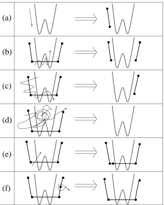
The user’s marks are interpreted as gestures, with the default being the construction of silhouette and border line segments. Other gestures add breakpoints for the classification process, delete breakpoints, delete a segment or an entire chain of segments, and clear all segments, as shown schematically in figure 3.5 (our gestures are similar to those of Tsang et al. [15]). The different gestures are based on intersections of the current line (the one the user is drawing) with already existing lines or with itself. In order to speed up intersections calculations, the segments are placed in a regular 2D grid as soon as they are created, allowing to significantly reduce the number of necessary tests.
The breakpoint-deletion gesture matches well with the standard typsetting deletion-mark; the other deletion gestures require multiple intersections with existing strokes to prevent accidental deletions.
3.3
Interpreting sketches of garments: basic ideas
For the sake of clarity, we’ll assume that the character is aligned with the xy-plane, viewed along the z direction (see figure 3.6).
The user draws the contours of the 2D projection of the garment in the (x, y) plane over the rendered character model, i.e. one or several cyclic chain(s) of strokes (the non-closed chains are not taken into account for the remainder of the algorithm). From these, we need to infer the z-information at every point of the contour and the interior of the garment (since we only deal with closed curves, we clearly have an inside region). Obviously this problem is under-constrained; fortunately, by considering the special nature of clothing, we can generate a plausible guess of the user’s intentions. In particular, silhouettes of clothing not only indicate points where the normal is in image plane, they usually occur as the clothing passes around the body, so we can estimate the z-depth of a silhouette edge as being the z-depth of the nearest point on the body (or, for a body placed fairly symmetrically about the xy-plane, simply use z = 0 as a quicker estimate). Moreover, the distance from a silhouette to the body helps us to infer the distance elsewhere, since a cloth
3.3 Interpreting sketches of garments: basic ideas 13
(a)
(b)
(c)
(d)
(e)
(f)
Figure 3.5: The gestures in the interface; the model is drawn in thick lines, prior strokes as medium lines with dots at breakpoints, and new strokes with thin lines; the arrowhead on the new-stroke lines is not actually drawn by the user, but merely indicates the direction in which the stroke is drawn. (a) adding a segment; (b) deleting a segment (stroke must intersect the segment at least five times); (c) deleting several segments (the stroke must intersect more than one segment, and intersect segments at least five times. If the stroke intersects segments from two different chains, both chains are deleted entirely.); (d) clearing all segments (the stroke must intersect some segment and count at least fourty intersections) (e) adding a breakpoint (f ) deleting a breakpoint (the stroke must intersect the segments on either side of the breakpoint, and intersect itself once).
14 PR OPOSED METHOD
Figure 3.6: A screenshot of the system, showing the (x,y,z) coordinate system used in 3D, and the corresponding 2D projection of the model on which the user is going to draw.
which tightly fits the body in the (x, y) plane will also tend to fit it in the other directions, while a loose cloth will tend to float everywhere.
3.3.1
Overview of the algorithm
Our algorithm, whose different steps will be detailed in the following sections, develops as follows:
1. Design the 2D sketch of the garment:
• The user draw the garment’s contour over a 2D projection of a 3D model (pre-computed).
• Find high-curvature points (breakpoints) that split the contours into segments. • Let the user add and/or delete breakpoints.
• Classify segments of curve between breakpoints into border lines (which cross the character’s body) or silhouette lines.
2. Infer the 3D position of silhouette and border lines:
• For each breakpoint that does not lie over body, find distance to body, d, and set the point’s depth, z, to the depth of the closest point on the body.
• For each silhouette line, interpolate z linearly over the interior of the line, and use interpolated z-values to compute d-values (distance to the body in the 3D space) over the interior of the line.
• For each border line, interpolate d over interior linearly to establish a desired distance to the model and set a z value for each point on the line;
3. Generate the interior shape of the garment:
• Create a mesh consisting of points within the 2D simple closed curve that the user has drawn, sampled on a rectangular grid in the (x, y) plane.
• Extend the values of d, which are known on the boundary of this grid, over the interior.
• For each interior grid point (x, y), determine the value of z for which the distance from (x, y, z) to the body is the associated value of d.
3.3 Interpreting sketches of garments: basic ideas 15
• Adjust this tentative assignment of z values to take into account the surface tension of the garment between two limbs of the character.
• Tesselate the grid with triangles, clipped to the boundary curves, and render the triangles.
3.3.2
Pre-computing a distance field
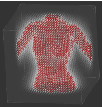
Figure 3.7: Point rendering of a 32 × 32 × 32 distance field computed for the top of a woman body. The red dots correspond to negative distances, or points inside the volume bounded by the surface. The transparency of each point is proportional to its distance to the body.
To accelerate steps 2 and 3 of the algorithm above, a distance field to the character’s model is pre-computed when the model is loaded (see figure 3.7): for each point in a 3D grid around the model, we determine and store the signed distance (a negative distance corresponds to a point inside the volume bounded by the surface, which has to be watertight) to the nearest point of the model, using an octree-based algorithm with exact point-to-triangle distance computations, similar to [11].
The distance field will be used each time we need to find the z coordinate to assign to a point p(x0, y0) so that it lies at a given distance from the model. This can easily be done
by stepping along the ray R(z) = (x0, y0, z) and stopping when the adequate distance value
is reached (we interpolate tri-linearly to estimate distances for non-grid points). When this computation is performed during a sweeping procedure, the stepping starts at the z value already found at a neighbouring pixel, which ensures the spatial coherence of the result and efficiency. Else, the process starts near the near plane of our rectangular frustum, in which the distance field has been computed.
The quality of the results depends directly on the resolution of the 3D grid storing the distance field, as does computation time. The size of the 3D grid is user-configurable, but we have generally used a 32 × 32 × 32 grid.
16 PR OPOSED METHOD
3.4
Processing of contour lines
3.4.1
2D processing
First, one must classify the parts of the user’s sketch. As the user sketches, a new line that starts or ends near (within a few pixels of) an endpoint of an already-sketched line is assumed to connect to it. In the same time, the sketched lines are broken into segments by detecting points of high (2D) curvature (breakpoints) on-the-fly. When the sketch is complete (i.e., forms a simple closed curve in the plane), we classify the parts:
• Each segment is classified as a silhouette or border line: border lines are those whose projection meets the projection of the body in the xy-plane, silhouettes are the others. The mask of the body’s projection is pre-computed and stored in a buffer called the body mask, in order to make this classification efficient.
• The resulting segmentation is visible to the user, who may choose, if necessary, to add or delete breakpoints indicating segment boundaries, after which segments are re-classified.
3.4.2
Distance and z-value at breakpoints
Breakpoints that are located over the body model (detected using the body mask) are used to indicate regions of the cloth that fit very tightly to the body. They are thus assigned a zero distance to the model, and their z value is set to the body’s z at this specific (x, y) location.
To assign a distance value d to a breakpoint that does not lie over the body, we step along the ray from the eye in the direction of the breakpoint’s projection into the xy-plane, checking distance values in the distance field data structure as we go, and find the z-value at which this distance is minimized. We assign to the breakpoint the discovered z and d values, thus positioning the breakpoint in 3D.
3.4.3
Line positioning in 3D
Our aim is to use the 3D position of the breakpoints we just computed to roughly position the garment in 3D, while the garment’s shape will mostly be inferred from distances to the body along the sketch silhouettes.
To position the silhouette lines in 3D, we interpolate z linearly along the edge between the two breakpoints at the extremities of the silhouette. We then set the d-values for interior points of the silhouette to those stored in the pre-computed distance field. We could have instead interpolated d directly, and computed associated z-values, but if the body curves away from the silhouette curve, there may be no z value for which the interpolated d-value is the distance to the body; alternatively, we could compute d directly for each interior point and then assign the z-value of the closest body point, as we did with the breakpoints, but in practice this leads to wiggly lines because of the coarse grid on which we pre-compute the approximate distance-to-body.
Having established the values of z and d along silhouette edges, we need to extend this assignment to the border lines. We do this in the simplest possible way: we assign d linearly along each border line. Thus, in the skirt example shown above, the d-values at the two ends of the waistline are both small, so the d-value for the entire waistline will be small, while the d-values for the ends of the hemline are quite large, so the values along the remainder of the hemline will be large too.
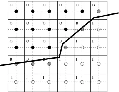
3.5 3D Reconstruction of the garment’s surface 17 B B B B B B I I I I I I I I I I I I O O O O O O O O O O O O
Figure 3.8: Each grid point represents a small square (solid lines). If a contour (heavy line) meets a small vertical or horizontal line through the pixel center (dashed lines), the pixel is classified as a boundary; boundary pixels are marked with a “B” in this figure. Others are classified as inside (“I”) or outside (“O”) by propagation of “O” values.
3.5
3D Reconstruction of the garment’s surface
3.5.1
Using distance to guess surface position
As for the contour lines, the interpolation of distances to the body will be our main cue to infer the 3D position of the interior of the garment. The first process thus consists in propagating distance values inside the garment. This is done in the following way:
The 2D closed contour lines of the garment are used to generate a (x, y) buffer (sized to the bounding box of the sketch) in which each pixel is assigned one of the values ‘in’, ‘out’ or ‘border’, according to its position with respect to the contour. A border pixel is one for which some contour line intersects either the vertical or horizontal segment of length one passing through the pixel-center (see figure 3.8); other pixels are inside or outside, which we determine using a propagation of ‘out’ values from the outer limits of the buffer.
The distance values already computed along the silhouette and border lines are assigned to the border pixels. The distances for the ‘in’ pixels are initialized to the mean value of distances along the contour.
Then, distance information is propagated inside the buffer by applying several iterations of a standard smoothing filter, which successively recomputes each value as an evenly weighted sum (with coefficients summing to 1) of its current value and those of its “in” or “boundary” orthogonal or diagonal neighbours (see figure 3.9). The iterations stop when the maximum difference between values obtained after two successive iterations is under a threshold, or if a maximum number of steps has been reached. Convergence generally seems to be rapid, but we have not proven convergence of the method in general.
We then sweep in the 2D grid for computing z values at the inner pixels: as explained in section 3.3.2, the z value is computed by stepping along a ray in the z direction, starting at the z value we already assigned for a neighbouring point, and taking the z the closest to the desired distance value, as stored in the pre-computed distance field.
18 PR OPOSED METHOD
Figure 3.9: The arrows indicate which neighboring pixels contribute to a pixel during the smoothing process: only neighboring boundary or inside pixels contribute to the average.
3.5.2
Mimicking the cloth’s tension
The previous computation gives a first guess of the garment’s 3D position, but still results in artefacts in regions located between two limbs of the character: due to surface tension, a cloth should not tightly fit the limbs in the in-between region (as in figure 3.10 (top)), but rather smoothly interpolate the limb’s large z value, due to its surface tension.
To achieve this, we first erode the 2D body mask (already mentioned in section 3.4.1) of a proportion that increases with the underlying d value (see figure 3.10) (bottom left)). We then use a series of B´ezier curves in horizontal planes to interpolate the z values for the pixels in-between. We chose horizontal gaps because of the structure of the human body: for an upright human (or most other mammals), gaps between portions of the body are more likely to be bounded by body on the left and right than to be bounded above and below.
To maintain the smoothness of the garment surface near the re-computed region, dis-tances values are extracted from the new z values and the distance field. Some distance propagation iterations are performed again in 2D, before re-computing the z values int the regions not lying over the body that haven’t been filled with the B´ezier curves, as was done previously (see figure 3.10 (right)).
We finally add a smoothing step on the z values in order to get a smoother shape for the parts of the cloth that float far from the character’s model. This is done computing a smoothed version of the z-buffer from the application of a standard smoothing filter, and then by taking a weighted average, at each pixel, of the old and smoothed z-values, the weighting coefficients depending on the distance to the model at this pixel.
3.5.3
Mesh generation
Finally, the triangles of the standard diagonally-subdivided mesh are used as the basis for the mesh that we render (see figure 3.11): all “inside” vertices are retained; all outside vertices and triangles containing them are removed, and “boundary” vertices are moved to new locations via a simple rule:
3.5 3D Reconstruction of the garment’s surface 19
Figure 3.10: Surface reconstruction without (top) versus with (bottom) taking tension effects into account. The part of the surface over the body mask is shown in green in the left images. At bottom left, the body mask has been eroded and B´ezier curves used to infer the z-values between the legs. The resulting z-buffers are shown in the middle images and the reconstructed surfaces on the right.
A
B
C
Figure 3.11: When a segment ends in a pixel’s box, the pixel center gets moved to that endpoint as in the box labelled “A.” If more than one segment ends, the pixel center is moved to the average, as in “B”. Otherwise, the pixel center is moved to the average of the intersections of segments with vertical and horizontal mid-lines, as in “C”.
20 PR OPOSED METHOD
the average of the endpoints of those segments. (Because segments tend to be long, it’s rare to have more than one endpoint in a box).
• Otherwise, some segment(s) must intersect the vertical and/or horizontal mid-lines of the box; the vertex is moved to the average of all such intersections.
3.6
Implementation
Figure 3.12: A screenshot of the system, showing the different modules: on the left, the preatreatment window (responsible for loading the model, and computing the distance field and the body mask), in the middle the drawing canvas, and on the right the resulting 3D surface.
Ease of use has been a central concern during all the developpment of the system. To make the interface as intuitive and efficient as possible, we thought that is was important for the user to be able to see immediately what are the consequences of his actions, at any time. For that reason, the system is composed of modules that have the ability to communicate with each other and exchange information. Each module comes with a view that can be displayed along with the others (see figure 3.12), hence giving the user the possibility to visualize simultaenously the impact of a modification in one module on all the other ones. The most obvious interest of that feature is to be able to see the inferred 3D surface from the sketch the user is being drawing.
Technically speaking, the system has been implemented in C++, using the libraries OpenGL1 , Qt2 and libQGLViewer3 . 1 http://www.opengl.org/ 2 http://www.trolltech.com/products/qt/ 3 http://artis.imag.fr/Software/QGLViewer/
C
HAPTER
4
R
ESULTS
Figure 4.1: Gallery of examples of garments created with our system.
The examples presented in figure 4.1, figure 4.2, figure 4.3 and on the cover of this report were drawn in no more than 5 minutes each. We want to point out that the jagged appearance of the strokes in the drawings is simply due to the use of a mouse instead of a more adequat graphics tablet as the input device. The galleries include simple clothes such as pullovers, skirts, dresses and shirts, but also less standard ones such as an “arabian like” pair of trousers along with basic jewelry, or eccentric outfits that would certainly fit nicely in a Haute couture collection. This wide range of types of cloth gives an idea of the expressivity our system provides the user with.
22 RESULTS
23
C
HAPTER
5
P
ERSPECTIVES AND CONCLUSIONS
5.1
Discussion
We have presented a method for dressing virtual characters from 2D sketches of their garments. We used the distance from the 2D garment silhouette to the character model to infer the variations of the distance between the garment and the character in 3D. The garment surface is generated from the silhouette and border lines and this varying distance information, thanks to a data-structure which stores the distance field to the character’s body. This method has been integrated in an interactive system in which the user can interactively sketch a garment and get its 3D geometry in a few minutes.
We have claimed at the beginning of this report that a sketching interface for garment design, making the creation of clothes intuitive and easy, would raise a certain enthusiasm from the multimedia industry. To validate this assumption, our system has been presented to actors of the video game market, who have indeed shown a strong interest in our tech-nology, and seriously consider either using or commercializing it in a near future.
The automated inference of the shape is simple and easy-to-understand, but may not be ideal in all cases, and we have not yet provided a way for the user to edit the solution to make it better match the idea that she or he had when sketching.
5.2
Future work
To infer the shape of a full garment, we could use symmetry constraints around each limb to infer silhouettes for the invisible parts, and ask the user to sketch (if he wants to) the border lines for the back view, for instance.
Most clothes are only slightly deformable, so the garment we sketch should be locally developable into a plane everywhere. We did not take this kind of constraint into account in our model, but this would be an interesting basis for future work, including the automatic inference of darts and gussets as in [12].
We’d also like to allow the user to draw folds, and take them into account when recon-structing the 3D geometry, so that even for a closely-fitting garment, there can be extra material, as in a pleated skirt. For that, we envision two solutions: either we modify the surface directly in 3D, using a deformation such as the one described in [13], or we work on the patterns in 2D, adding fabric where the user wants folds to appear.
Finally, we have sketched clothing as though it were simply a stiff polygonal material unaffected by gravity. We would like to allow the user to draw clothing, indicate something about the stiffness of the material, and see how that material would drape over the body. The difference between silk (almost no stiffness), canvas (stiff), and tulle (very stiff) can generate very different draping behaviors. In the much longer term, we’d like to incorporate a simulator that can simulate the difference between bias-cut cloth and straight-grain, the former being far more “clingy” than the latter.
B
IBLIOGRAPHY
[1] T. Bonte, A. Galimberti, and C. Rizzi, A 3D graphic environment for garments design, Kluwer Academic Publishers, 2002, pp. 137–150.
[2] D. Bourguignon, M.-P. Cani, and G. Drettakis, Drawing for illustration and annotation in 3D, Computer Graphics Forum, 20 (2001). ISSN 1067-7055.
[3] U. Cugini and C. Rizzi, 3d design and simulation of men garments, in WSCG proceedings, 2002, pp. 9–16.
[4] E. Drudi and T. Paci, Figurines de mode et stylisme, The Pepin Press, 2001. [5] L. Eggli, C. yao Hsu, B. D. Bruderlin, and G. Elber, Inferring 3d models from
freehand sketches and constraints, Computer-Aided Design, 29 (1997), pp. 101–112. [6] T. Fleisch, G. Brunetti, P. Santos, and A. Stork, Stroke-input methods for
immersive styling environments, in Proceedings of the 2004 International Conference on Shape Modeling and Applications, June 7–9, Genova, Italy, 2004, pp. 275–283. [7] B. Hinds and J. McCartney, Interactive garment design, The Visual Computer, 6
(1990), pp. 53–61.
[8] T. Igarashi and J. F. Hughes, Clothing manipulation, in Proceedings of the 15th annual ACM symposium on User interface software and technology, ACM Press, 2002, pp. 91–100.
[9] T. Igarashi, S. Matsuoka, and H. Tanaka, Teddy: a sketching interface for 3d freeform design, in Proceedings of the 26th annual conference on Computer graphics and interactive techniques, ACM Press/Addison-Wesley Publishing Co., 1999, pp. 409– 416.
[10] P. J. Ireland, Fashion design, drawing and presentation, Batsford limited, 1982. [11] M. W. Jones and R. Satherley, Using distance fields for object representation and
rendering, in Proceedings of the19th Ann. Conf. of Eurographics (UK Chapter), 2001, pp. 91–100.
[12] J. McCartney, B. K. Hinds, and B. L. Seow, The flattening of triangulated surfaces incorporating darts and gussets, Computer Aided Design, 31 (1999), pp. 249– 260.
[13] K. Singh and E. Fiume, Wires: a geometric deformation technique, in Proceedings of the 25th annual conference on Computer graphics and interactive techniques, ACM Press, 1998, pp. 405–414.
[14] C. Tatham and J. Seaman, Fashion design drawing course, Barron’s, 2003. [15] S. Tsang, R. Balakrishnan, K. Singh, and A. Ranjan, A suggestive interface for
image guided 3d sketching, in Proceedings of CHI 2004, April 24–29, Vienna, Austria, 2004, pp. 591–598.
28 BIBLIOGRAPHY
[16] H. M. Werner, N. Magnenat-Thalmann, and D. Thalmann, User interface for fashion design, in Proceedings of the IFIP TC5/WG5.2/WG5.10 CSI International Conference on Computer Graphics, North-Holland, 1993, pp. 197–204.
[17] R. C. Zeleznik, K. Herndon, and J. F. Hughes, Sketch: An interface for sketch-ing 3d scenes, in Computer Graphics Proceedsketch-ings, SIGGRAPH’96, Annual Conference Series, New Orleans, Louisiana, August 1996, ACM.

![Figure 2.2: (left) The system introduced in [2] allows the user to visualize 2D sketches drawn from multiple views in 3D, which can be useful for experimenting with ideas of design, even though no surface is generated](https://thumb-eu.123doks.com/thumbv2/123doknet/15042341.692011/12.892.154.741.144.351/figure-introduced-visualize-sketches-multiple-experimenting-surface-generated.webp)