HAL Id: cea-01217058
https://hal-cea.archives-ouvertes.fr/cea-01217058
Submitted on 18 Oct 2015
HAL is a multi-disciplinary open access
archive for the deposit and dissemination of sci-entific research documents, whether they are pub-lished or not. The documents may come from teaching and research institutions in France or abroad, or from public or private research centers.
L’archive ouverte pluridisciplinaire HAL, est destinée au dépôt et à la diffusion de documents scientifiques de niveau recherche, publiés ou non, émanant des établissements d’enseignement et de recherche français ou étrangers, des laboratoires publics ou privés.
Chromatism compensation of the PETAL multipetawatt
high-energy laser
Jérôme Neauport, N Blanchot, C Rouyer, C Sauteret
To cite this version:
Jérôme Neauport, N Blanchot, C Rouyer, C Sauteret. Chromatism compensation of the PETAL multipetawatt high-energy laser. Journal of Optics A: Pure and Applied Optics, IOP Publishing, 2007, �10.1364/AO.46.001568�. �cea-01217058�
Chromatism compensation of the PETAL multipetawatt
high-energy laser
J. Néauport, N. Blanchot, C. Rouyer, and C. Sauteret
High-energy petawatt lasers use series of spatial filters in their amplification section. The refractive lenses employed introduce longitudinal chromatism that can spatially and temporally distort the ultra-fast laser beam after focusing. To ensure optimum performances of petawatt laser facilities, these distortions need to be corrected. Several solutions using reflective, refractive, or diffractive optical components can be addressed. We give herein a review of these various possibilities with their application to the PETAL (Petawatt Aquitaine Laser at the Laser Integration Line facility) laser beamline and show that diffractive-based corrections appear to be the most promising. © 2007 Optical Society of America
OCIS codes: 140.7090, 050.5080.
1. Introduction
The past decade has seen the development of num-bers of ultrahigh-energy laser facilities driven by fast ignition and inertial confinement fusion application advances.1High-energy petawatt projects like
Omega-Extended Performance2 (Laboratory for Laser
En-ergetics, University of Rochester, USA), National Ignition Facility (NIF) Petawatt Laser3 (Lawrence
Livermore National Laboratory, USA), PICO20004 petawatt laser (Laboratoire pour l’Utilisation des Lasers Intenses, France), Vulcan Petawatt Laser5
(Rutherford Appleton Laboratory, UK), Petawatt Aquitaine Laser (PETAL)6(Commissariat a l’Energie
Atomique, France), and the Fast Ignition Realization Experiment (FIREX)7 (Institute of Laser
Engineer-ing, Japan) will allow unique experiments in the field of ultrahigh intensity sciences, extreme plasma phys-ics, astrophysphys-ics, radiography, and demonstration of fast ignition by combination of petawatt or multipe-tawatt, kilojoule beams and nanosecond multikilo-joule beams. In all these laser systems, amplifiers are separated by large spatial filters. These spatial
fil-ters, using a pair of refractive lenses, are used to clean the beam of unwanted intensity modulations at high spatial frequencies8and also to extend and兾or
to image the spatial profile on each amplifier stages. In single-pass amplifier systems, spatial filters are passed once, while in multipass amplifier configura-tions, spatial filters can be passed two to four times, depending on the choice of architecture. Because of the dependence of the glass index with wavelength, in traversing of a refractive lens a polychromatic light is focused in multiple foci along the lens axis, each cor-responding to a given wavelength. This aberration is known as longitudinal chromatic aberration9and is
additive. For spatial filters, this effect ensures that only the central wavelength is collimated while the other wavelengths acquire a divergence or a conver-gence. For long-pulse laser systems such as NIF10or
Laser Megajoule (LMJ)11, this effect can be neglected.
But for short pulses, i.e., of large spectral bandwidth, this chromatic aberration can significantly distort temporally and spatially the beam in the focal plane. This phenomenon has been previously described by Bor12and needs to be corrected for most of the
peta-watt class laser facilities.
Many solutions exist to correct the longitudinal chromatism of spatial filters lenses; they were subse-quently studied in the field of short pulses,13
micros-copy,14 or lens design for visible wavelength.15 The
most classical method consists of employing achro-matic doublets made of two different glasses.9
An-other solution based on the same principle is to replace some plane mirrors by an adequate coupling of a diverging lens and a spherical mirror. One can also take advantage of the inverse chromatic
aberra-J. Néauport ( jerome.neauport@cea.fr), N. Blanchot, and C. Rouyer are with the Commissariat à l’énergie atomique, Centre d’études scientifiques et techniques d’Aquitaine, B.P. 2, 33114 Le Barp, France. C. Sauteret is with the Laboratoire pour l’Utilisation des Lasers Intenses, Ecole Polytechnique, Unité mixte de Recher-che 7605, 91128 Palaiseau, France.
Received 6 September 2006; revised 9 November 2006; accepted 29 November 2006; posted 1 December 2006 (Doc. ID 74766); pub-lished 1 March 2007.
0003-6935/07/091568-07$15.00/0 © 2007 Optical Society of America
tion of a diffractive optic such as a grating or a Fresnel zone plate.16 –18 Last, it is also possible to
design a null power triplet compensating the chro-matic aberration.
This paper is divided in three parts. The amplifier section of the PETAL facility is depicted in Section 2 with details of the chromatic aberration to be cor-rected. We then review the various compensation so-lutions with their feasibility in our facility. Section 3 is thus devoted to the analysis of correcting solution using glasses of various types based on the achro-matic doublet principle. Section 4 focuses on the use of diffractive optics for chromatism correction. 2. Petawatt Aquitaine Laser Amplifier Section
The PETAL facility is designed to deliver 3.6 kJ of energy in in 500 fs at the wavelength of 1.053m and is an additional short pulse beam to the Laser Inte-gration Line (LIL)11 facility. The PETAL amplifier
section has the same architecture as the LIL兾LMJ amplifier section19 using a single 400 mm ⫻ 400 mm
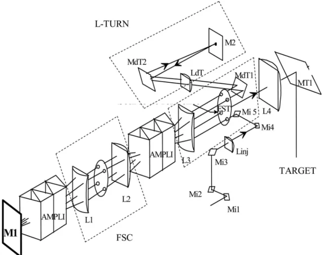
beam. It is a four-pass system with angular multi-plexing and an L-turn (see Fig. 1). It uses 16 amplifier laser slabs arranged in two sets. The front-end pulse (up to 100 millijoules) is injected in the transport spatial filter (FST), passes into amplifier groups, bounces on the M1 deformable mirror, and passes a
second time in the 16 slabs. The beam is reflected off Mdt1 into the L-turn, reflects on the M2 mirror, and goes back on M1 and then exits the amplifier section after L4, the last lens of FST. It is then sent to the transport section and focused after compression20with
a parabola into the center of the vacuum chamber. The delay introduced by a single lens can be ex-pressed as21 ⌬T ⫽ r 2 2cf共n ⫺ 1兲 dn d ⫽ ⫺ r2 2cf2 df d, (1)
where f is the focal length of the lens, is the central wavelength, n is the refractive index of glass, c is the velocity of light, and r is the distance of the marginal ray from the axis.
If we now consider a series of spatial filters con-sisting of N lenses, the effect is additive, and the total delay becomes ⌬T ⫽
兺
i⫽1 N ri2 2cfi共ni⫺ 1兲冉
dn d冊
i. (2)After final focusing with a reflective parabola of focal length F and half-diameter r, this total pulse delay
Fig. 1. PETAL amplifier section baseline with angular multiplexing. The L-turn is realized with two mirrors (Mdt2, M2). The transport spatial filter (FST) and cavity spatial filter (FSC) are surrounded.
corresponds to the following focal shift [Eq. (3)], where fiand␦fiare the focal length and focal shift of
lens i. ⌬F共兲 ⫽F 2 r2 i
兺
⫽1 N ri2 fi冋
␦fi共兲 fi册
⫽ F2 r2 ⫻ 共 ⫺ 0兲 0 ⫻ 2c ⫻ ⌬T. (3) The focal shift divided by the Rayleigh distance to the target is therefore proportional to the cumulated de-lay of the marginal ray divided by the pulse duration,⌬F
Z ⫽K⫻
⌬T
. (4)
Here Z is the Rayleigh distance on the target, is the pulse duration, and K is a form factor equal to 8 for a Gaussian beam with a Gaussian spectrum.
In the case of our PETAL amplifier section, all lenses are made of fused silica (Corning 7980). The index is
n ⫽ 1.449 and dn兾d ⫽ ⫺1.22 ⫻ 10⫺5nm⫺1 at the wavelength of 1.053m. Table 1 summarized the delay contribution of each lens of our amplifier sec-tion. Overall, due to large component size, a total delay of 1520 fs is introduced in traversing the lenses of our system. This quantity at the edge of the square beam is almost three times the expected duration of the PETAL laser pulse and reaches four times this pulse duration for the corner of the square beam. Numerical simulations6 have shown that both
tem-poral and spatial distortions are combined and in-duce a decrease of the peak intensity on target by a factor of 8 compared to the ideal case (no chroma-tism). Consequently, a chromatism compensator has to be implemented in the laser system.
3. Reflective-Refractive-Based Chromatism Corrections
Wavelength dependence of the refractive index of a given glass is usually expressed by glass manufactur-ers by its Abbé number [see Eq. (5)], where nD, nF,
and nCare the indices for the three visible emission
rays of sodium and hydrogen 共589.3 nm, 486.1 nm, and 656.3 nm, respectively)22:
⫽nnD⫺ 1
F⫺ nC
. (5)
This Abbé number is suitable for correction to be made in the visible range. First-order chromatism compensation then takes benefits of the existence of two main family of glasses called flint glass (low in-dex and high Abbé number) and crown glass (high index and low Abbé number). Adequate combination of these glasses can be used to compensate chromatic aberration.
Transposition of this principle to high-power laser facilities operating at 1.053m must take into ac-count several additional criteria or constraints:
Y Glass must be chosen based on its index n and wavelength dependence dn兾d at 1.053 nm. For the PETAL facility a typical spectrum of 3 nm is used in the amplifier section.
Y Glass must exhibit a high damage threshold. Typical values of a few J兾cm2to 20 J兾cm2at 1.053m
for 3 ns pulses are to be considered at the PETAL facility depending on the lens to be corrected in the amplifier section.
Y Glass must exhibit a low nonlinear index n2to limit the B-integral to a value that avoids any self-focusing phenomenon8,23 and compressed pulse
pro-file distortions.
Y Glass must be feasible in rather large size (see Table 1 for PETAL lenses) and with a high refractive-index homogeneity and transparency at 1.053m. Most of these data can be found in the glass manu-facturers catalog (Hoya, Corning, Schott, or others); we based our calculation on and referenced our glasses to the Schott optical glass catalog.24
Laser-induced damage threshold values could be found in work from Hack et al.25Authors made an extensive
study of the damage threshold at the wavelength of 1.064m for pulses duration of 3 ns of many differ-ent optical glasses and detailed some nonlinear index values as well. Additional data regarding nonlinear index could also be found in Adair et al.26Let us now
consider a correction with a first lens made of fused-silica 7980 from Corning (equivalent to the crown glass described above); then the flint glass could be, for example, LF5 or LLF-1 Schott glass. For LF-5, we have n ⫽ 1.556, dn兾d ⫽ ⫺1.69 ⫻ 10⫺5nm⫺1, and
n2⫽ 2.73 ⫻ 10⫺13e.s.u at the wavelength of 1.053m,
equivalent8to ␥ ⫽ 7.35 ⫻ 10⫺16cm2兾W. Most of the
high-index homogeneity optical glasses are not avail-able at sizes of more than 180 mm⫻ 180 mm. More-over, platinum inclusions can be a major issue for operation on high-power laser facilities. Significant efforts can be made to limit the number and size of these inclusions while preserving high-index homo-geneity for specific large productions27; in our case
this was not economically viable. Therefore, refrac-tive correction is limited to a part with a section of less than 180 mm⫻ 180 mm.
A. Achromats
The simplest method to correct chromatism of a sin-gle thin lens is to replace it by an achromat made of two thin lenses in contact made of two different
Table 1. Delay Contribution of Each Lens of the Petawatt Aquitaine Laser Amplifier Section
Lens Focal Length (mm) Half-Diameter (mm) Delay (fs) Number of Passes Total Delay (fs) Linj 2765 18.76 6 1 6 L3 26282 178.32 58 4 231 L2 9972 178.32 152 4 608 L1 9791 175.08 149 4 597 Ldt 5000 33.92 11 2 22 L4 26282 178.32 58 1 58
glasses. As explained before, for PETAL, this correc-tion is practically limited to the injeccorrec-tion lens Linj and L-turn lens Ldt due to size availability consider-ations. The Ldt fused-silica lens with a focal point of 5 m can be replaced by an achromatic doublet with a fused-silica converging lens and a LF5 diverging lens with the following surface radii, R1 ⫽ 0.46 m, R⫽ ⫹0.5 m, and R2⫽ ⫺0.98 m, for example 共R ⬎ 0 for
convex). Because it is limited to Linj and Ldt, Table 1 shows that a delay of only 28 fs can be compensated with this technique, which is insufficient.
B. Plane Mirror Substitution by an Equivalent Diverging Lens and Concave Mirror Combination
Alternatively, one can also benefit from the inverse chromatism of a diverging lens by replacing a plane mirror by an equivalent combination of a concave spherical mirror and diverging lens28(see Fig. 2). For
the PETAL amplifier section, it can be done by chang-ing the L-turn mirror M2 by this optical system. The beam half-section on the M2 mirror is 33.92 mm. The induced delay is then calculated with Eq. (1). Trying to compensate the whole 1520 fs delay of our system with this combination leads to a LF5 diverging lens of focal length f⫽ ⫺80.8 mm. Good transmitted wave-front quality of an almost f兾1 lens can be difficult to achieve, in particular for modulations at mid spatial frequencies where strict specifications are needed for these types of laser facilities.29
Regarding the B-integral, the nonlinear index of LF5 is three times bigger than the nonlinear index of fused silica. Therefore the Kerr effect induced by the double pass in the LF5 compensation lens will lead to an increase of the B-integral of the system. This contribution ⌬B is given by the equation ⌬B ⫽ 2 ⫻ 共2兾兲 ⫻ ␥ ⫻ I ⫻ e with typical values of the thickness
e⫽ 1 cm and intensity of I ⫽ 4.108W兾cm2. The
ob-tained B-integral contribution of ⌬B ⫽ 3.5 ⫻ 10⫺2 radians can consequently be neglected, showing that nonlinear contribution is not an issue in this case. Let us outline that the contribution of the corrector di-verging element to the B integral could be minimized by using calcium fluoride instead of LF5 optical glass. But since calcium fluoride30has a dn兾d of
approxi-mately ⫺6 ⫻ 10⫺6nm⫺1 around 1m, i.e., three times less than LF5, it would lead to a
nonmanufac-turable lens or to a possible delay compensation of a third of our total delay. Based on lens manufacturing difficulties, this correction principle cannot be re-tained for the PETAL laser facility.
C. Null Power Compensation System
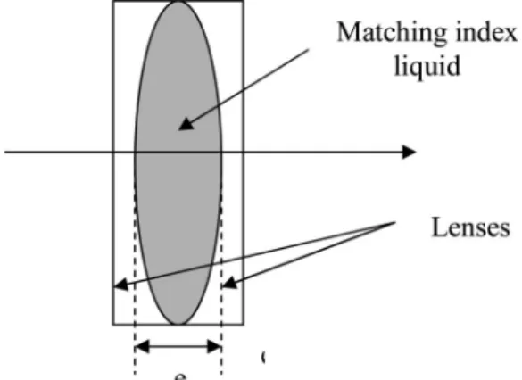
The principle of this compensation null power system is to use two plano-concave lenses of the same radius with their spherical surfaces facing each other (see Fig. 3). A matching index liquid is then placed between the two spherical surfaces. Lenses and matching-index liq-uid are chosen to have the same index around 1m. If
e is the distance difference between marginal and
on-axis rays in the liquid, the delay introduced by this combination is given by
⌬T ⫽c
冋冉
dnd冊
glass⫺
冉
dn
d
冊
liq册
⫻ e, (6) where 共dn兾d兲glass and 共dn兾d兲liq denote thedepen-dence of index of glass and matching-index liquid versus wavelength.
For a configuration with two fused-silica lenses and a Cargille code 653031matching-index liquid, we
obtain a maximal delay compensation of 165 fs for
e ⫽ 10 mm, equivalent to f兾3 lenses for a system
implemented in the L-turn. This delay compensation is insufficient to be used in our PETAL system. More-over, incertitude exists on the optical quality in trans-mission of such liquids and on their nonlinear index. In consequence, this solution was abandoned. 4. Diffractive-Based Chromatism Corrections
A. Principle
Holograms such as diffraction gratings have been widely used for achromatization since they exhibit an inverse chromatism compared to transparent mate-rials. Modern optical design often benefits from this behavior.15–18
Let us consider a focusing grating of focal length f (see Fig. 4). In the first diffracted order, sin␣共r, 兲 ⫽
N共r兲 ⫻ , where N共r兲 is the line density of the grating
Fig. 2. Optical system equivalent to a plane mirror. Curvature center of mirror C and lens focus point F are placed at the same position.
Fig. 3. Null power compensation system. Two plano-concave lenses with interspace filled with matching-index liquid of the same index as the lenses.
at the marginal ray r. In the paraxial approximation,
f⫽ r兾␣ ⫽ r兾N共r兲 ⫻ . Therefore chromatic aberration
of the grating can be expressed as df
d ⫽ ⫺
f
. (7)
Bor demonstrated21 that part two of Eq. (1) stays
valid in the case of a Fresnel zone plate, and it can be extended as well to our focusing grating operating in its first order. Therefore the delay introduced by the grating can be expressed by combining Eqs. (1) and (7):
⌬T ⫽ ⫺r 2 2cf2 df d ⫽ r2 2cf ⫽ rN 2c . (8)
By another way, Fig. 5 shows that this delay⌬T can be directly obtained by the difference between the marginal ray length and the axial ray length, r2兾共2f兲.
The groove density of the grating for a ray having a distance h from the optic axis is expressed by the relation N共h兲 ⫽ h兾f. When the ray is translated along the pupil periphery, it covers the mth groove. After passing a unique groove of a grating, the wave takes a delay of a period of the wave, i.e.,兾c. Thus, if m grooves of the grating are seen by the wave, the delay is, thanks to the quadratic variation of the line den-sity of the focusing grating, expressed as
⌬T ⫽ mc ⫽ r 2 2f ⫻ c ⫽ rN 2c . (9)
The number m of grooves therefore appears indepen-dent of the diffractive corrector characteristics, such as focal length or aperture diameter. Typically, to
compensate the 1520 fs delay of the PETAL facility, the diffractive corrector will have m grooves, with m equal to
m⫽c⫻ ⌬T
⫽ 433 grooves. (10)
Application of the principle of this diffractive chro-matic aberration can be done in the case of our PETAL facility by replacing, for example, the L-turn mirror M2 by an equivalent combination of a converg-ing diffractive lens and convex spherical mirror on the equivalent baseline of Subsection 3.B. Equation (8) gives the focal length of the diverging element. For r⫽ 33.92 mm on the M2 mirror, we find a focal length of f ⫽ 2.523 m. This corresponds to a line density of N ⫽ 12.767 lines兾mm. Such a low line-density grating would exhibit very low diffraction efficiency. Thus in our high-power laser application, diffractive Fresnel lenses32are preferred. It consists
of a Fresnel lens with a binarized one-wave-deep pro-file. Using a four-mask manufacturing process, the 16 level diffractive Fresnel lenses can exhibit a theoret-ical diffraction efficiency of 98.5%.
We therefore see that our whole 1520 fs compen-sation can be made by a Fresnel convergent diffract-ing 16 level lens placed in our L-turn with a line density on the marginal ray of 12.767 lines兾mm. Other difficulties shall be addressed with this pecu-liar component, such as wavefront quality in both mid and high frequencies18and ghost beams due to
the diffractive nature of the device. Damage thresh-old shall not be an issue since a bare fused-silica part is used. These specific points will be addressed in a future work.
B. Second-Order Chromatism Correction
The chromatic aberration compensation calculated in the previous subsections assumes that dependence of the index versus wavelength is linear. When this linear contribution is corrected, a nonlinear contribu-tion called the second-order chromatism still remains. The quantitative effect of the second-order chromatism is estimated in this paragraph.
We herein assume that the chromatic “linear” ab-erration is compensated in our PETAL baseline by adding a Fresnel diffractive lens such as depicted in Subsection 4.A. Second-order chromatism of the dif-fractive compensator can be expressed by derivation of Eq. (7) at the second order:
d2f
d2⫽
2f
2. (11)
Expanding the wavelength dependent of the focal length, we have
冉
␦f f冊
dif⫽ ⫺ ⌬ ⫹ ⌬2 2 ⫹ O冋冉
⌬ 冊
3册
. (12)Fig. 4. Focusing grating.
Fig. 5. Delay⌬T corresponds to the difference of the marginal and axial ray lengths.
For the refractive lenses, we have with the same way,
冉
␦f f冊
ref⫽ ⫺ ⌬ 共n ⫺ 1兲 dn d ⫹冋
1 共n ⫺ 1兲2冉
dn d冊
2 ⫺2共n ⫺ 1兲1 d 2n d2册
⌬ 2⫹ O冋冉
⌬ 冊
3册
. (13) The longitudinal chromatism⌬z relative to the Ray-leigh distance Z can be expressed thanks to Eq. (3) and with separation of refractive and diffractive con-tribution by ⌬z Z ⫽ 1 再冋
i兺
⫽1 P ri2 fi冉
␦fi共兲 fi冊
册
ref ⫹冋
兺
j⫽1 M rj2 fj冉
␦fj共兲 fj冊
册
dif冎
. (14) Combination of Eqs. (12), (13), and (14) and annula-tions of the first-order term in ⌬ achieved by the first-order correction gives the following relations:⌬z Z ⫽ ⌬2 2
冉
兺
j⫽1 M rj2 fj冊
dif冋
1 ⫹冉
d2 n兾d2 2dn兾d ⫺ 1 n⫺ 1 dn d冊册
. (15)For our correction of Subsection 4.B with a diffractive Fresnel of focal length f ⫽ 2.523 m and radius
r ⫽ 33.92 mm, a spectrum of ⌬ ⫽ 3 nm, we have
⌬z兾Z ⫽ 4.4 ⫻ 10⫺3. This second-order chromatism
can thus be neglected. 5. Conclusions
Without any correction, the PETAL high-energy peta-watt laser beam presents a chromatism that can re-duce the intensity on target by a factor of 8. We have therefore reviewed various types of chromatic aberra-tion correcaberra-tions for their applicaaberra-tion to this facility. We have shown that, for compensation of the 1520 fs pulse broadening, refractive-based solutions offered low in-terest and small amount of time compensation. More-over, high nonlinear index and small size availability of the optical glass to be used induced many con-strains. Diffractive compensation solutions appear to be the most adequate solution. We have thus demon-strated that only one Fresnel diverging diffractive lens can be used for the compensation of the whole chromatism of our amplifier section. In this case, the second-order chromatism is negligible. Consequently, this diffractive correction principle is retained in the baseline of PETAL. Efforts are now made to check position of ghost beams and to make some experimen-tal validations of a diffractive Fresnel lens manufac-tured from the calculation herein detailed.
This work is supported by the Conseil Régional d’Aquitaine and is performed under the auspices of the Institut Lasers et Plasmas.
References
1. J. D. Zuegel, S. Borneis, C. Barty, B. Le Garrec, C. Danson, N. Miyanaga, P. K. Rambo, C. Le Blanc, T. J. Kessler, A. W. Schmid, L. J. Waxer, J. H. Kelly, B. Kruschwitz, R. Jungquist,
E. Moses, J. Britten, I. Jovanovic, J. Dawson, and N. Blanchot, “Laser challenges for fast ignition,” in special issue on fast ignition, Fus. Sci. Technol. 49, 453 (2006).
2. L. J. Waxer, D. N. Maywar, J. H. Kelly, T. J. Kessler, B. E. Kruschwitz, S. J. Loucks, R. L. McCrory, D. D. Meyerhofer, S. F. B. Morse, C. Stoeckl, and J. D. Zuegel, “High-energy petawatt capability for the Omega laser,” Opt. Photon. News
16, 30 (2005).
3. C. P. J. Barty, M. Key, J. Britten, R. Beach, G. Beer, C. Brown, S. Bryan, J. Caird, T. Carlson, J. Dawson, A. C. Erlandson, D. Fittinghoff, M. Hermann, C. Hoaglan, A. Iyer, L. Jones II, I. Jovanovic, A. Komashko, O. Landen, Z. Liao, W. Molander, S. Mitchell, E. Moses, N. Nielsen, H.-H. Ngyuen, J. Nissen, S. Payne, D. Pennington, L. Risinger, M. Rushford, K. Skulina, M. Spaeth, B. Stuart, G. Tietbohl, and B. Wattellier, “An over-view of LLNL high-energy short-pulse technology for advanced radiography of laser fusion experiments,” Nucl. Fusion 44, S266 –S275 (2004).
4. C. Le Blanc, C. Felix, J. C. Lagron, N. Forget, Ph. Hollander, A. M. Sautivet, C. Sauteret, F. Amiranoff, and A. Migus, “The petawatt laser glass chain at LULI: from the diode-pumped front end to the new generation of compact compressors,” in
Proceedings of Third International Conference on Inertial Fu-sion Sciences and Applications, B. A. Hammel, D. D.
Meyer-hofer, J. Meyer ter Vehn, and H. Azechi, eds. (American Nuclear Society, 2004), pp. 608 – 611.
5. C. N. Danson, P. A. Brummitt, R. J. Clarke, J. L. Collier, B. Fell, A. J. Frackiewicz, S. Hancock, S. Hawkes, C. Hernandez-Gomez, P. Holligan, M. H. R. Hutchinson, A. Kidd, W. J. Lester, I. O. Musgrave, D. Neely, D. R. Neville, P. A. Norreys, D. A. Pepler, C. J. Reason, W. Shaikh, T. B. Winstone, R. W. W. Wyatt, and B. E. Wyborn, “Vulcan petawatt–an ultra-high-intensity interaction facility,” Nucl. Fusion 44, S239 –S246 (2004).
6. N. Blanchot, E. Bignon, H. Coïc, A. Cotel, E. Couturier, G. Deschaseaux, N. Forget, E. Freysz, E. Hugonnot, C. Le Blanc, N. Loustalet, J. Luce, G. Marre, A. Migus, S. Montant, S. Mousset, S. Noailles, J. Néauport, C. Rouyer, C. Rullière, C. Sauteret, L. Videau, and P. Vivini, “Multi-petawatt high en-ergy laser project on the LIL facility in Aquitaine,” in Topical
Problems of Non-linear Wave Physics, A. Sergeev, ed., Proc.
SPIE 5975, 30 (2005).
7. K. Mima, H. Azechi, Y. Johzaki, Y. Kitagawa, R. Kodama, Y. Kozaki, N. Miyanaga, K. Nagai, H. Nagatomo, M. Nakai, H. Nishimura, T. Norimatsu, H. Shiraga, K. Tanaka, Y. Izawa, Y. Nakao, and H. Sakagami, “Present status of fast ignition research and prospects of FIREX project,” Fus. Sci. Technol.
47, 662 (2005).
8. W. Koechner, “Damage of optical elements,” in Solid-State
Laser Engineering, 5th ed., Vol. 1 of Springer Series in Optical
Sciences (Springer-Verlag, 1999), pp. 676 – 677.
9. M. Born and E. Wolf, Principle of Optics, 7th ed. (Cambridge University), p. 186.
10. B. M. Van Wonterghem, S. C. Burkhart, C. A. Haynam, K. R. Manes, C. D. Marshall, J. E. Murray, M. L. Spaeth, D. R. Speck, S. B. Sutton, and P. J. Wegner, “National Ignition Fa-cility commissioning and performance,” in Optical Engineering
at the Lawrence Livermore National Laboratory II: The Na-tional Ignition Facility, M. A. Lane and C. R. Wuest, eds., Proc.
SPIE 5341, 55– 65 (2004).
11. C. Cavailler, N. Fleurot, T. Lonjaret, and J. M. Di-Nicola, “Prospects and progress at LIL and Megajoule,” Plasma Phys. Controlled Fusion 46, B135–B141 (2004).
12. Z. Bor, “Distortions of femtosecond laser pulses in lens systems,” J. Mod. Opt. 35, 1907–1918 (1988).
13. R. Piestun and D. B. Miller, “Spatiotemporal control of ultra-short optical pulses by refractive-diffractive-dispersive struc-tured optical elements,” Opt. Lett. 26, 1373–1375 (2001).
14. U. Fuchs and U. D. Zeitner, “Hybrid optics for focusing ultra-short laser pulses,” Opt. Lett. 31, 1516 –1518 (2006). 15. T. Stone and N. George, “Hybrid diffractive-refractive lenses
and achromats,” Appl. Opt. 27, 2960 –2971 (1988).
16. H. Madjidi-Zolbanine and C. Froehly, “Holographic correction of both chromatic and spherical aberrations of single glass lenses,” Appl. Opt. 18, 2385–2393 (1979).
17. H. M. Heuck, P. Neumayer, T. Kühl, and U. Wittrock, “Chromatic aberration in petawatt-class lasers,” Appl. Phys. B
84, 421– 428 (2006).
18. T. J. Kessler, H. Huang, and D. Weiner, “Diffractive optics for compensation of axial chromatic aberration in high-energy short-pulse laser,” in Proceedings of the International
Confer-ence on Ultrahigh Intensity Lasers (International Committee
on Ultra-High Intensity Lasers, 2006), pp. 126 –128. 19. M. L. André, “Status of the LMJ project,” in Solid State Lasers
for Applications to Inertial Confinement Fusion: Second An-nual International Conference, M. L. André, ed., Proc. SPIE 3047, 38 (1997).
20. N. Blanchot, G. Marre, J. Néauport, E. Sibé, C. Rouyer, S. Montant, A. Cotel, C. Le Blanc, and C. Sauteret, “Synthetic aperture compression scheme for multi-petawatt high energy laser,” Appl. Opt. 45, 6013– 6021 (2006).
21. Z. Bor, “Distortion of femtosecond laser pulses in lenses,” Opt. Lett. 14, 119 –121 (1989).
22. M. W. Farm and W. B. Veldkamp, “Binary optics,” in
Hand-book of Optics, 2nd ed., M. Bass, ed. (McGraw-Hill, 1995), p. 86.
23. V. I. Bespalov and V. I. Talanov, “Filamentary structure of
light beams in non-linear liquids,” JETP Lett. 3, 307–310 (1966).
24. Schott Optical Glass, Inc., 400 York Avenue, Duryea, Pa. 18642; http://www.schott.com.
25. H. Hack and N. Neuroth, “Resistance of optical and colored glasses to 3 ns laser pulses,” Appl. Opt. 21, 3239 –3248 (1982). 26. R. Adair, L. L. Chase, and S. A. Payne, “Nonlinear refractive index of optical crystals,” Phys. Rev. B 39, 3337–3350 (1989). 27. J. H. Campbell, “Damage resistant optical glasses for high power lasers: a continuing glass science and technology chal-lenge,” Glass Sci. Technol. 75, 91–108 (2002).
28. M. Martinez, E. Gaul, T. Ditmire, S. Douglas, D. Gorski, W. Henderson, J. Blakeney, D. Hammond, M. Gerity, J. Caird, A. Erlandson, I. Iovanovic, C. Ebbers, and B. Molander, “The Texas Petawatt Laser,” in Laser-Induced Damage in Optical
Materials: 2005, G. J. Exarhos, A. H. Guenther, K. L. Lewis, D.
Ristau, M. J. Soileau, and C. J. Stolz, eds., Proc. SPIE 5991, 1N-1 (2005).
29. M. Bray, A. Liard, and G. Chabassier, “Laser megajoule optics (I): New methods of optical specifications,” in Optical
Fabrica-tion and Testing, R. Geyl and J. Maxwell, eds., Proc. SPIE 3739, 449 – 460 (1999).
30. M. Daimon and A. Masumura, “High accuracy measurements of the refractive index and its temperature coefficient of cal-cium fluoride in a wide wavelength range from 138 to 2326 nm,” Appl. Opt. 41, 5275–5281 (2002).
31. CARGILLE Laboratories, Inc., 55 Commerce Road, Cedar Grove, N.J. 07009-1289 USA; http://www.cargille.com. 32. http://www.llnl.gov/nif/last/diffractive-optics/fresnel.html.