HAL Id: hal-00809644
https://hal.inria.fr/hal-00809644
Submitted on 2 May 2019
HAL is a multi-disciplinary open access
archive for the deposit and dissemination of
sci-entific research documents, whether they are
pub-lished or not. The documents may come from
teaching and research institutions in France or
abroad, or from public or private research centers.
L’archive ouverte pluridisciplinaire HAL, est
destinée au dépôt et à la diffusion de documents
scientifiques de niveau recherche, publiés ou non,
émanant des établissements d’enseignement et de
recherche français ou étrangers, des laboratoires
publics ou privés.
Modeling Timing Requirements in Problem Frames
Using CCSL
Chen Xiaohong, Jing Liu, Frédéric Mallet, Zhi Jin
To cite this version:
Chen Xiaohong, Jing Liu, Frédéric Mallet, Zhi Jin. Modeling Timing Requirements in Problem Frames
Using CCSL. APSEC 2011 - 18th Asia Pacific Software Engineering Conference, Dec 2011, Ho Chi
Minh, Vietnam. pp.381-388, �10.1109/APSEC.2011.30�. �hal-00809644�
Modeling Timing Requirements in Problem Frames Using CCSL
Xiaohong Chen∗‡, Jing Liu∗, F r´ed´eric Mallet†and Zhi Jin‡
∗Shanghai Key Laboratory of Trustworthy Computing, East China Normal University
†U niversit´e Nice-Sophia Antipolis, INRIA Sophia Antipolis M ´editerran´ee
‡Key Laboratory of High Confidence Software Technologies, Ministry of Education, Peking University
Abstract—As the embedded systems are becoming more and more complex, requirements engineering approaches are needed for modeling requirements, especially the timing re-quirements. Among various requirements engineering ap-proaches, the Problem Frames(PF) approach is particularly useful in requirements modeling for the embedded systems due to the characteristic that PF pays special attention to the environment entities that will interact with the to-be software. However, no concern is given on timing requirements of PF at present. This paper studies how to add timing constraints on problem domains in PF. Our approach is to integrate the prob-lem representation frame in PF with the timing representation mechanism of MARTE(Modeling and Analysis of Real Time and Embedded systems). A unified problem frame modeling process integrated with timing constraints is provided, and problem frame requirements with timing constraints expressed by MARTE/CCSL(Clock Constraint Specification Language) and clock construction operators are obtained.
Keywords-requirements engineering; timing requirements; Problem Frames approach; CCSL; embedded systems;
I. INTRODUCTION
Timing requirements are especially important in the em-bedded systems. For example, in the signalling system for high-speed trains, timing requirements are specified for avoiding train collision. In this kind of systems, timing requirements are critical for preventing damages and pro-tecting the lives of people. This is immediately clear for all applications in the transport sector including computer controlled cars, trains and planes.
Addressing this problem, the MARTE [1](Modeling and Analysis of Real Time and Embedded systems) has recently been adopted by the OMG as a standard modeling language for real-time and embedded applications. It defines a broadly expressive Time Model that embodies a generic timed inter-pretation of UML models. Its notion of time covers both physical and logical times which is modeled by multiform time. Besides, many prevalence requirements engineering approaches start to pay attention to the timing requirements. For instance, the goal-oriented approaches [2], which take the system goals as the source of the requirements, capture the timing requirements with the typed first-order real-time logic. The agent oriented approaches [3], which use inten-tional actors as main clue to identify the requirements, also use the first-order logic to specify the timing requirements. The Problem Frames (PF) approach [4] is a new and
promising requirements engineering approach for describ-ing, analyzdescrib-ing, and classifying software problems. It empha-sizes that requirements exist in the environment of the to-be software, i.e. the problem domains that will interact with the to-be software. Therefore, the PF concentrates on the descriptions of the entities that will interact with the to-be software, and interactions between the entities and the to-be software. Compared with the goal oriented approaches and the agent oriented approaches, the PF approach is distinguished for its environment perspective. It is especially useful in embedded systems due to the above characteristics. However, no concern is given on the timing requirements in PF. A timing requirements modeling mechanism is needed. This paper aims to study how to add timing constraints on problem domains in PF. Starting from modeling the time of a problem domain with a clock, this paper proposes to integrate the problem representation frame in PF with the timing representation mechanism of MARTE. In order to do this, a new icon, problem domain with clock which is formed by attaching a clock icon to the problem domain icon in the PF, is designed. A few clock construction operators in terms of problem domains are defined. At last, a unified problem frame modeling process integrated with timing constraints is provided, and problem frame requirements with timing constraints expressed by MARTE/CCSL(Clock Constraint Specification Language)[5] and clock construction operators are obtained.
In this paper, we focus on three kinds of timing require-ments [5]:
• DelayRequirement that constrains the delay “from” a set of entities “until” another set of entities. It specifies the temporal distance between the execution of the earliest “from” entity and the latest “until” entity;
• RepetitionRate that defines the triggering period of an elementary Function;
• Input/outputSynchronization that expresses a timing requirement on the input/output synchronization of an Function.
The rest of this paper is organized as follows. Sec-tion II gives a brief introducSec-tion to the PF approach and MARTE/CCSL. Section III presents a timing conceptual model for PF with basic concepts in MARTE/CCSL. Sec-tion IV defines three clock construcSec-tion operators in terms of
problem domains. Section V presents a unified requirements modeling process integrated with timing constraints, and shows the feasibility with an Anti-lock Braking System (ABS). Section VI presents some related work. Finally, Section VII concludes the paper.
II. BACKGROUND
A. Problem Frames approach
The PF approach was first introduced into requirements engineering by Michael Jackson in 2001. In PF, software requirements are expressed as the expected changes on prob-lem domains. These changes will be realized by building a software via the interaction between the software and the problem domains. Thus, in the PF approach, software requirements include identification of problem domains and interactions between the to-be software and the problem domains. Device Controller machine Work regime (the solution) {is_on, is_off}
(the context) (the requirement)
Figure 1. A simple problem diagram [6]
The result of the requirements description is a problem diagram. Fig. 1 gives a simple example of a problem diagram [6]. In the figure, the software problem is to specify a machine (the solution) to control a device (the problem context, consisting of a single problem domain in this case) so that a certain work regime (the requirement) is satisfied. The link between device and machine called interaction in the example indicates the phenomena that are shared between them. Phenomena can be, for instance, events or states or values. In this example, the shared phenomena are commands that the controller machine can issue to switch the device on and off (That such phenomena are controlled by the controller machine is indicated by a ! after the abbreviation CM). Phenomena is on and is off are the expected changes on the device. They are expected to happen between the machine and devices, so they are also a kind of interactions.
B. MARTE/CCSL
MARTE is a response to the OMG RFP to provide a UML Profile aiming at bringing in modeling software of the real-time and embedded domain. And CCSL is a non-normative language annexed to MARTE specification. As a declarative language that specifies constraints imposed on the clocks of a model, CCSL is widely used to support the specification of systems with multiple clock domains. In order to do this, it defines a set of elements required to support real-time and embedded domain. The following will give some definitions of the concepts that are used in this paper.
A clock is a model giving access to the time structure in MARTE[7]. Formally it is defined as a 5-tuple.
Definition 1: Clock
Clock,< I, ≺, D, λ, u >
where,
• I is a set of instants
• ≺ is a quasi-order relation on I, named strict
prece-dence
• D is a set of labels
• λ : I→ D is a labeling function
• u is a symbol, standing for a unit
For simplicity, this paper adopts a simplified definition of
Clock =< I,≺>.
Instants in clocks have relations. These relations can be unified defined as binary relation on set of instants:
IR : Instant× Instant
Here three kinds of IR are distinguished:
• Precedence (≼): it represents causal dependency rela-tion between instants. It has the following properties: (1) reflexive, that is∀a ∈ Instant, we have a ≼ a, (2) transitive, that is ∀a, b, c ∈ Instant, if a ≼ b , b ≼ c, then we have a≼ c.
• Coincidence (≡,≼ ∩ ≽): it is a strong relation that forces simultaneous occurrences of instants. It has symmetric characteristic, that is ∀a, b ∈ Instant, if
a≡ b, then b ≡ a.
• Strict precedence (≺,≼ \ ≡): it represents the sequen-tial relation of occurrences of instants. It has transitive characteristic, that is ∀a, b, c ∈ Instant, if a ≺ b ,
b≺ c, then we have a ≺ c.
There are also a lot of operators for constructing new clocks using existing clocks. Here, we just list some opera-tors that are related to this paper.
Definition 2: FilteredBy (H)
A, BHω, where A and B are discrete clocks, and ω is
a binary word. A is constructed by B using
∀i ∈ IA,∃j ∈ IB
idexA(i) = ω↑ idexB(j)
where IA is the instants set of A, IB is the instants set
of B, ω↑ k is the index of the kth1 in ω.
This operator allows the selection of a subset of instants.
Definition 3: inf and sup
For clocks A and B, C = inf (A, B) is the slowest clock faster than both A and B,
∀k ∈ N\{0}, C[k]=if A[k] ≼ B[k] thenA[k] else B[k]
For clocks A and B, D = sup(A, B) is the fastest clock among all clocks slower than both A and B,
∀k ∈ N\{0}, D[k]=if A[k] ≼ B[k] then B[k] else A[k]
where A[k] means the kth instant of A.
Definition 4: a− b < t
a− b < t <=> b < a < b + t on sec, where a and b are
instants, ”+” is the delay operator and sec is another clock that discretize the IdealClock(can be seen as a real watch clock) each and every second.
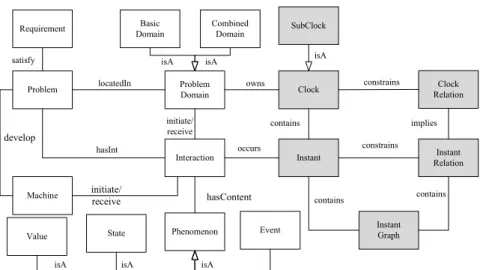
Problem Domain Interaction Clock Clock Relation Instant Problem Instant Relation isA constrains Machine Phenomenon Event Value
isA isA isA State Requirement develop satisfy locatedIn initiate/ receive initiate/ receive hasInt hasContent owns contains constrains implies SubClock Instant Graph contains Basic Domain Combined Domain isA isA contains occurs
Figure 2. The timing PF conceptual model
III. ATIMINGPFCONCEPTUAL MODEL
We have previously developed a conceptual model for describing software problems based on PF [8]. In this paper, we extend this conceptual model by associating the functionality related concepts with the time related concepts, so that a timing PF conceptual model is constructed. Fig. 2 shows the new conceptual model.
In Fig. 2, the white boxes and the links between them represent the concept categories and the associations be-tween them based on the PF approach. They capture the main idea in the PF approach: a Problem is located in a set of real world Problem Domains, and is to develop a
Machine to satisfy Requirements. A problem domain can be
a Basic Domain or a Combined Domain. There are shared phenomena between the machine and the problem domains, i.e., Interactions between the Machine and the Problem Domains. An interaction has one initiator and one receiver that could be a machine or a problem domain. In fact, each interaction represents one individual action that the machine is involved in.
The gray boxes shows the time related concepts. These concepts are elicited from MARTE [9]. Time can be seen as a collection of Clocks. A clock may have many subClocks. Each clock specifies a totally ordered set of Instants. The relations between instants are called Instant Relations. To visually see the instants and instant relations, an Instant
Graph is defined. Besides, there are relations between clocks
which are called Clock Relations.
These two groups of concepts are related through the following relations. Each problem domain owns one clock. Interactions of each problem domain can be directly bound to time: the occurrences of interactions refer to time points, i.e., instants of related clocks.
Table I gives the exact meaning of the above concepts. Based on the extended timing model in Fig. 2, formal
Table I
HIERARCHY OF THECONCEPTCATEGORIES
Concept Meaning
Problem a problem is a task to be accomplished by
software development
Machine the system to be built in a problem
ProblemDomain a relevant real world entity that will interact
with the machine
BasicDomain a real world entity
CombinedDomain entity that is composed by several basic domains
Requirement functionalities which need to be satisfied
Interaction an interaction is an observable phenomena
shared by machine and a domain
Phenomenon a phenomenon can be of state, value and event
Event an event is an individual happening. Each
event is indivisible and instantaneous
Value a value is an intangible individual that is
not subject to change
State a state is a relation among causal domains
and values. It can change over time
Clock a clock is a virtual instrument used to indicate,
keep, and coordinate time
subClock a clock coordinates with another clock
Instant the time point that interaction occurs
Instant Relation the order relation between instants
Clock Relation the relation between clocks
Instant Graph a directed graph whose nodes are instants and the
edges express the relations between two instants
definitions of interaction and instant graph can be given. An interaction can be defined as a triple.
Definition 5: Interaction
Interaction,< initiator, receiver, content >
where,
• initiator is the problem domain or machine that
initi-ates the phenomenon
• receiver is the problem domain or machine that
re-ceives the phenomenon
• content is the shared phenomenon
Definition 6: Instant Graph
InstantGraph,< Ins, Rels >
where,
• Ins is a set of interactions
• Rels is the set of instant relations between the elements
in Ins
The instant relation can be precedence, coincidence or strict precedence as introduced in section II. These relations and their notations are shown in Fig. 3 [7].
i i j j i j i j
i j i<j
Coincidence Precedence Strict Precedence
Figure 3. Legend of instant graph
IV. CLOCK CONSTRUCTION OPERATORS
This section intends to define some clock construction operators. MARTE/CCSL defined many clock operators. But none of them concern problem domains. As the clocks within our model concern the problem domains, the original clock construction operators in CCSL need to be extended. Some new operators needs to be defined here.
Considering the problem domains in PF, clock construc-tion operators can be defined in two ways. One way is for the same problem domain. In this situation, a new clock is defined by adding new instants to existing clock of the same problem domain. The other way is for the problem domains combination. That is, the existing problem domains may be too trivial, but the combination of these domains need to be modeled. After new problem domain being identified, the clock of combined domain is defined by combination of clocks of each problem domain.
Before we continue, some assumptions need to be made. A clock is either dense or discrete in MARTE. This paper only deals with discrete clocks. A discrete-time clock C for problem domain d can be denoted as d.C. It has a discrete set of instants, named IC. Since ICis discrete, it can be indexed
by natural numbers in a fashion that respects the ordering on
IC: let N∗= N\{0}, idx : IC→ N∗,∀i ∈ IC, idx(i) = k
if and only if i is the kthinstant in I
C. Suppose c[k] denotes
the kthinstant in I
C(i.e., k = idxC(C[k])). For any instant
i ∈ IC, i− 1 is the unique immediate predecessor of i in
IC.
A. Operators for the same problem domain
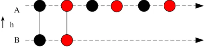
Here we consider one situation when some interactions turn out to happen periodically. Then a new clock needs to be constructed by adding periodical instants to the old one. This operator is using FilteredBy operator in CCSL:
Definition 7: d.A, d.BH0o.(1.0p−1)ω
where, d is a problem domain, p is the period, o is the offset, A is the new clock of d, B is the existing clock of
d consisting in using a binary word with a single 1 in the
periodic part. In this expression, for any bit b, b0stands for the empty binary word.
Intuitively, this means that many new instants are iden-tified in clock A while repeating the same interactions in clock B. This is shown in Fig. 4.
A
B
↑
hFigure 4. Instant graph for adding periodical interactions
B. Operators for the combined problem domains
The combination of problem domains can be classified into two kinds according to the domain structure. One kind is that domain d1 and d2 are sharing the same structure.
For example, sensor1 and sensor2 of the same type are the same structured sensors. In terms of interactions, if they share the same phenomenon with the machine through interactions, they are the same structured domains, which is thus defined.
Definition 8: The same structured domains
Suppose hasContent(X) returns the phenomenon that interaction X has. If for any interaction X of domain d1,
a corresponding interaction Y of domain d2 can always be
found such that
hasContent(X) = hasContent(Y )
and vice versa. Then d1 and d2 are the same structured
domains.
In this situation, the combination of d1 and d2 acts like
one domain d, and the clock of d can be defined by instants either in the clock of d1 or clock of d2. The instants of d
will always be the slowest instants in d1 and d2. Thus, the
construction operator of the same structured domain union can be defined as:
Definition 9: d.A, d1.B⊕ d2.C
Where, B is the discrete clock for domain d1, and clock C
is for domain d2, d1and d2are the same structured domains,
domain d is the union of d1 and d2, then the clock d.A is:
∃hb : IB→ IA,∃hc : IC→ IA, such that
1) hb, hc is injective
2) hb, hc is order preserving:
(∀i, j ∈ IB)(i≺B j)⇒ (hb(i) ≺Ah(j))
(∀i, j ∈ IC)(i≺Cj)⇒ (hc(i) ≺Ah(j))
3) an instant of IB and its image are precedent:
(∀i ∈ IB)i≼ h(i) (∀i ∈ IC)i≼ h(i)
4) ∀iB[k]∈ IB,∀iC[k]∈ IC
iA[k] = sup(iB[k], iC[k])
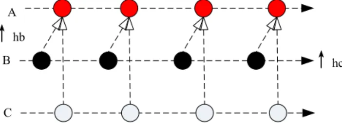
Intuitively, this means that each instant in clock A is the lowest instant happened in clock B and clock C. This can be seen in Fig. 5.
A
B
↑
hbC
↑
hcFigure 5. Instant graph for combining the same structured domains
The other situation is that the to-be combined domains are totaly different. Their interactions are quite different from each other. The clock of the union of these domains is the combination of clocks for basic domains by grouping instants happened in these domains together. Thus, the union operator for different problem domains can be defined:
Definition 10: d.A, d1.B∪ d2.C
Where, B is the discrete clock for domain d1, and clock
C for domain d2, d1 and d2 are different domains, domain
d is the union of d1 and d2, then the clock d.A is:
∃hb : IB → IA,∃hc : IC → IA, such that
1) hb, hc is injective
2) hb, hc is order preserving:
(∀i, j ∈ IB)(i≺Bj)⇒ (hb(i) ≺Ah(j))
(∀i, j ∈ IC)(i≺Cj)⇒ (hc(i) ≺Ah(j))
3) an instant of IB and its image are coincident:
(∀i ∈ IB)i≡ h(i)
(∀i ∈ IC)i≡ h(i)
4) IA= IB∪ IC
∀iB[m]∈ IB,∀iC[n]∈ IC, iB[m]≺ iC[n]
hb(iB[m])≺Ahc(iC[n])
Intuitively, the instants of clock A are all the instants of clock B and C. It must be noticed that clock B and clock
C are not asynchronous. This can be seen in Fig. 6. A
B
↑
hbC
↑
hcFigure 6. Instant graph for combining different domains
V. TIMING REQUIREMENTS MODELING PROCESS:AN
EXAMPLE
Fig. 7 gives a unified requirements modeling process by adding timing constraints to functional requirements obtained in PF. The input of this process is a problem diagram which includes problem domains, interactions etc.. It can be obtained by following process in [10]. The output is
Append clock icon for each problem domain Draw instant graph Product Problem Diagram Clock Construction Operators
Model clock for each basic problem domain
Model clock for each combined domain Timing requirements Specify quantitative constraints on instants
Activity Control Support
Instant Graph Knowledge base 1 2 3 4 5
Figure 7. Timing requirements modeling process
timing requirements full of clock expressions in CCSL and clock construction operators defined in section IV. In Fig. 7 there are five main steps to guide the timing requirements modeling. We will use an example to the illustrate these steps. This example and the associated timing requirements are adapted from the ATESST report on EAST-ADL timing model [11]. The problem statements are as follows.
The ABS architecture consists of four sensors, four actuators and an indicator of the vehicle speed. The sensors ( ifl, ifr, irl, irr) measure the rotation speed of the vehicle wheels. The actuators (ofl, ofr, orr and orl) indicate the brake pressure to be applied on the wheels.
The execution of the ABS is triggered by R. The values of the four sensors involved in the ABS must arrive within some delay (InputSynchronization). A similar OuputSynchronization delay is represented on the actuators side. The delay from the first event on the input set of the ABS until the last event occurrence on the output set is also needed.
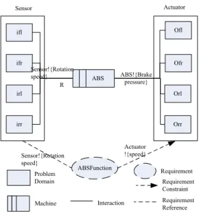
Example 1: The problem diagram of the ABS system is
shown in Fig. 8. In this figure the combined domain Sensor has four basic domains: ifl, ifr, irl and irr. Similarly, the combined domain Actuator has four basic domains: ofl, ofr,
orl, and orr. The interactions between ABS and Sensor, ABS and Actuator are asserted as follows:
int1=< ABS, Sensor, R >
int2=< Sensor, ABS, rotation speed >
int3=< ABS, Actuator, break pressure >
int4=< Actuator, ABS, speed >
Obviously, ofl, ofr, orl, orr and Sensor are the same structured domains, and ofl, ofr, orl, orr and Actuator are the same structured domains. For simplicity, this paper just uses intij (i can be 1, 2, 3, or 4, and j is the name of the
domain) to denote their interactions.
Step 1: append a clock icon to each problem domain This step is to declare clocks for problem domains. A particular way is to append a clock icon to each domain
ifr Ofr ifl irr Ofl Orl irl Orr ABS ABSFunction Actuator !{speed} ABS!{Brake pressure} Sensor!{Rotation speed} Sensor!{Rotation speed} R Sensor Actuator Problem Domain Interaction Machine Requirement Requirement Reference Requirement Constraint
Figure 8. Problem diagram of ABS
icon in the problem diagram.
Example 2: Back to our example, append a clock to each
problem domain in Fig. 8. Therefore Fig. 9 is obtained, and the following assertions can be got from Fig. 9:
Clock Senser.CSensor, Actuator.CActuator;
Clock if l.Cif l, if r.Cif r, irl.Cirl, irr.Cirr;
Clock of l.Cof l, of r.Cof r, orl.Corl, orr.Corr;
ifr Ofr ifl irr Ofl Orl irl Orr ABS ABSFunction Actuator !{speed} ABS!{Brake pressure} Sensor!{Rotation speed} Sensor!{Rotation speed} R Sensor Actuator Problem Domain Interaction Machine Requirement Requirement Reference Requirement Constraint Clock CSensor CAcutuator Cifl Cifr Cofl Clrl Cirr Cofr Corl Corr
Figure 9. Problem diagram of ABS with clocks
Step 2: model clocks for basic domains This step can be finished in two sub-steps: 1) find instants for each clock
The instants for each domain are the occurrences of interactions that related domain initiates or receives. So this step is to identify the occurrence of each interaction.
2) specify strict precedence of instant relations within each clock
This step is to specify the relations between instants.
Example 3: The basic domains in this example are
sensors if l, if r, irl, irr and actuators of l, of r, orl, orr. The moments that int1if l and int2if l happened are the
instants of Cif l, recording as O(int1if l), O(int2if l), then
Iif l={O(int1if l), O(int2if l)}. Similarly we get:
Iif l={O(int1if l), O(int2if l)};
Iif r={O(int1if r), O(int2if r)};
Iirl={O(int1irl), O(int2irl)};
Iirr={O(int1irr), O(int2irr)};
Iof l={O(int3of l), O(int4of l)};
Iof r={O(int3of r), O(int4of r)};
Iorl={O(int3orl), O(int4orl)};
Iorr={O(int3orr), O(int4orr)};
As to the instants relation, for example, in clock Cif l,
int1if l must happens before int2if l, so O(int1if l) ≺
O(int2if l). Similarly, the other strict precedence relations
can be obtained:
O(int1if l)≺ O(int2if l);
O(int1if r)≺ O(int2if r);
O(int1irl)≺ O(int2irl);
O(int1irr)≺ O(int2irr);
O(int3of l)≺ O(int4of l);
O(int3of r)≺ O(int4of r);
O(int3orl)≺ O(int4orl);
O(int3orr)≺ O(int4orr);
Step 3: model clocks for combined domains
This step is to construct clocks from existing clocks using combined clock construction operators defined in section IV. To do this efficiently, we’d better start by finding the combined domain and its basic domains.
Example 4: Sensor is the combination of if l, if r, irl,
and irr. Sensor if l, if r, irl and irr are the same structured domain, Thus, we have:
Sensor.CSensor=if l.Cif l⊕ ifr.Cif r⊕ irl.Cirl⊕ irr.Cirr
Similarly, we get:
Actuator.CActuator= Cof l⊕ofr.Cof r⊕orl.Corl⊕orr.Corr
Especially, the instant relations needs to be specified. In clock CSensor, the moments that int1 and int2
hap-pened are the instants of this clock. Recording them as
O(int1), O(int2), then ISensor = {O(int1), O(int2)}.
Considering the relations of Sensor , if l, if r, irl, and
irr, the occurrence of int1 should be the slowest among
the occurrences of int1if l,int1if r,int1irl, and int1irr, thus
we get:
O( int1)=sup(O(int1if l),O(int1if r),O(int1irl), O(int1irr))
Similarly we get:
O( int2)=sup(O(int2if l),O(int2if r),O(int2irl), Oint2irr))
In clock CActuator, IActuator ={O(int3), O(int4)}
Likewise, we get:
O(int3)=sup(O(int3of l),O(int3of r),O(int3orl), O(int3orr))
O(int4)=sup(O(int4of l),O(int4of r),O(int4orl), O(int4orr))
This step is to specify the instant relations within and among clocks visually. Usually we just specify the 3 rela-tions: precedence, coincidence, and strict precedence. The instants relations identify needs close participation of re-quirement providers.
Example 5: For example, between CSensor and
CActuator, int2happens before int3, so O(int2)≺ O(int3).
Between CSensor and Cif l, int1 happens no early than
int1if l, so O(int1if l)≼ O(int1).
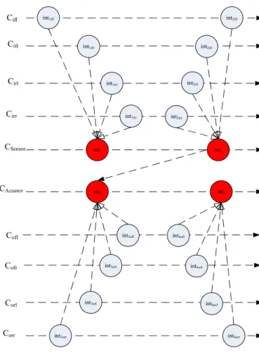
Similarly, we get the other instant relations as well as instant relations within one clock in step 2 as shown in Fig. 10.
int1 int2
int3 int4
CSensor
CAcuator
int1irl int2irl
int1ifr int2ifr
int1irr int2irr
int1ifl int2ifl
Corr
int3orl int4orl
int3ofr int4ofr
int3orr int4orr
int3ofl int4ofl
Corl Cofr Cofl Cirr Cirl Cifr Cifl
Figure 10. The instant graph for ABS
Step 5: specify quantitative constraints on instants This step is to specify the quantitative constraints on instants. For example, intervals between instants is no more than 5 seconds. Of course, not all the instants need to do this. Only some important instants are required.
Example 6: The three kinds of quantitative requirements
considered in this paper are as follows. 1) Repetition Rate
For example, this kind of requirements may be written as:
The ABS function must be executed every 5ms with a maximum jitter of 1ms.
This function will be implemented by the combination of
Sensor and Actuator periodically. Sensor and Actuator are
different domains, so the existing clock will be:
Sensor.CSensor∪ Actuator.CActuator
According to the periodic construction operator in section IV, the other parameters include the offset being 0 and the period being 5. Then the new clock Cnewis constructed as:
Cnew=(Sensor.CSensor∪ Actuator.CActuator)H(1.05−1)ω
2) Delay Requirement
This kind of requirements may be stated as:
At each iteration, the distance between the reception of the first input and the emission of the last output must be less than 3ms.
Take int1 of Sensor as an input, and int4 of Actuator
as an output. Then the first input can be written as:
O1inf = inf (O(int1if r), O(int1if l), O(int1irl), O(int1irr))
The emission of the last output is O(int4). And finally,
the interval between the two can be:
O(int4)− O1inf < 30
3) Input & output synchronization
Input & output synchronization are specializations of a delay requirement. An input synchronization delay require-ment for the Function ABS bounds the temporal distance between the earliest input and the latest input. For example,
an input synchronization of 0.5ms is needed.
The first input is O1inf, and the last input is O(int1).
Then the input synchronization of 0.5ms is:
O(int1)− O1inf < 5
Likewise, an output synchronization delay requirement for the Function ABS bounds the temporal distance between the earliest output and the latest output. For example, an output
synchronization of 0.5ms is needed.
The first output is:
O4inf = inf (O(int4of r), O(int4of l), O(int4orl), O(int4orr))
The last output is O(int4).Then the output
synchroniza-tion of 0.5ms is:
O(int4)− O4inf < 5
After the whole process, problem frame based require-ments are obtained. They not only includes the functional requirements in the form of original problem diagram, but also the timing requirements in the form of problem do-main clock icons and constraints through clock construction operators and CCSL.
VI. RELATED WORK
There are many efforts for modeling timing requirements. The goal oriented approaches [2] view goals as the source of requirements. One of the representative work is KAOS [2](Knowledge Acquisition in Automated Specification). The logic used in KAOS is typed first-order real-time logic. It consists of traditional temporal operators, together with additional real-time operators for specifying properties involving real-time deadlines. A key feature of the logic is
its ability to model real-time properties concisely without referring explicitly to a time variable.
The agent oriented approaches [3] use actor as a clue to identify requirements. Their representative work is i* framework [12] and Formal Tropos [13]. The Formal Tropos language offers all the primitive concepts of i*, but sup-plements them with a rich temporal specification language inspired by KAOS. Formal Tropos also uses a linear-time typed first-order temporal logic.
The other efforts of agent oriented have also been made to specify timing requirements. For example, ALBERT-II(Agent-Oriented Language for Building and Eliciting Real-Time Requirements) [14], a formal framework designed for specifying distributed real-time systems, is based on temporal logic. Agents’ states and behavior are specified through constraints expressed in the logic-based notation.
However, all the above approaches are based on the logic. A limitation of the logic currently used is that the time domain is assumed to be discrete. This makes it difficult to accurately capture and reason about properties involving time derivatives and integrals of time-continuous variables. Compared with these approaches, our approach is based on the MARTE/CCSL, a multiform timed system which is more close to the real world than the other general multiple clock systems. The time domain combines the discrete and continuous characteristics by using instants as the discrete time points. Another advantage of our approach is that our timing requirements are deeply rooted in the functional requirements.
VII. CONCLUSION
Timing requirements are of great importance in the em-bedded systems. In this paper, we propose an approach to model the timing requirements based on the PF approach using CCSL. The main contribution includes:
• A new timing PF model is constructed. This model introduces clocks for problem domains into PF, which makes timing requirements description in PF possible.
• A method for specifying timing requirements in PF is provided. This method is based on the functional re-quirements description in PF, which makes solid foun-dation for timing requirements description. It is fulfilled with timing constraints proposed in MARTE/CCSL. The timing requirements modeling results in timing problem frame requirements. Further work needs to be done for verifying timing requirements, and deriving machine speci-fications from the timing requirements. Besides, this paper only deals with three kinds of timing requirements. More timing requirements are under consideration.
ACKNOWLEDGMENT
The authors wish to thank Prof. Robert de Simone for his constructive comments and suggestions. This work was sup-ported by the National Basic Research and Development 973
Program of China (Grant No.2009CB320702), and National Natural Science Foundation of China (Grant No.90718014, No.90818026, No.61021004).
REFERENCES
[1] C. Andr´e, F. Mallet, and R. de Simone, “Modeling time(s),” Lecture Notes in Computer Science, vol. 4735, 2007. [2] A. van Lamsweerde, “Formal refinement patterns for
goal-driven requirements elaboration,” in Proceedings of the 4th ACM Symposium on the Foundations of Software Engineering (FSE4), San Francisco, USA, 1996, pp. 179–190.
[3] E.Yu, “Agent orientation as a modeling paradigm,” Wirtschaftsinformatik, vol. 43, no. 2, pp. 123–132, 2001. [4] M.Jackson, Problem Frames: Analyzing and Structuring
soft-ware development problems. Harlow, England:Addison-Wesley, 2001.
[5] F. Mallet, M. Peraldi-Frati, and C. Andr´e, “Marte CCSL to execute East-ADL timing requirements,” in Int. Symp. on Object/component/service-oriented Real-time distributed Computing (ISORC’09). Japan, Tokyo: IEEE Computer Press, March 2009, pp. 249–253.
[6] K. Cox, J. G. Hall, and L. Rapanotti, “A roadmap of prob-lem frames research,” Information and Software Technology, vol. 47, no. 14, pp. 891–902, 2005.
[7] C. Andr´e and F. Mallet, “Specification and verification of time requirements with ccsl and esterel,” in Proceedings of the 2009 ACM SIGPLAN/SIGBED conference on Languages, compilers, and tools for embedded systems, LCTES 2009, Dublin, Ireland, June 2009, pp. 167–176.
[8] Z.Jin, X.Chen, and D.Zowghi, “Performing projection in problem frames using scenarios,” in Proceedings of the 16th Asia-Pacific Software Engineering Conference(APSEC 2009), 2009, pp. 249–256.
[9] OMG, “Uml profile for modelling and analysis of real- time and embedded systems (marte),” http://www.omgmarte.org/. [10] X. Chen and Z. Jin, “An ontology-guided process for
develop-ing problem frame specification: an example,” in Proceeddevelop-ings of the 3rd International Workshop on Applications and Ad-vances of Problem Frames (IWAAPF 2008), 2008, pp. 36–39. [11] R. Johansson, H. Lonn, and P. Frey, “Atesst timing model,”
ITEA, Tech. Rep., 2008, deliverable D2.1.3.
[12] E. Yu, “Modelling organizations for information systems requirements engineering,” in Proceedings of First IEEE Symposium on Requirements Engineering, 1993, pp. 34–41. [13] E.Yu, “Towards modeling and reasoning support for
early-phase requirements engineering,” in Proceedings of the 3rd IEEE international Symposium on Requirements Engineering (RE’97). Washington DC: IEEE Computer Society, 1997, pp. 226–235.
[14] P. Bois, “The albert ii language - on the design and the use of a formal specification language for requirements analysis,” Ph.D. dissertation, Dept. of Computer Science, University of Namur, Namur, Belgium, 1995.