READ THESE TERMS AND CONDITIONS CAREFULLY BEFORE USING THIS WEBSITE. https://nrc-publications.canada.ca/eng/copyright
NRC Publications Archive
Archives des publications du CNRC
This publication could be one of several versions: author’s original, accepted manuscript or the publisher’s version. / La version de cette publication peut être l’une des suivantes : la version prépublication de l’auteur, la version acceptée du manuscrit ou la version de l’éditeur.
Access and use of this website and the material on it are subject to the Terms and Conditions set forth at
A Review of adhesion mechanisms at the crack sealant/ asphalt
concrete interface
Masson, J-F.; Lacasse, M. A.
NRC Publications Record / Notice d'Archives des publications de CNRC:
https://nrc-publications.canada.ca/eng/view/object/?id=2b54fb37-8afe-4af2-b9aa-e37af511667e https://publications-cnrc.canada.ca/fra/voir/objet/?id=2b54fb37-8afe-4af2-b9aa-e37af511667e
A REVIEW OF ADHESION MECHANISMS AT THE CRACK
SEALANT/ASPHALT CONCRETE INTERFACE
J-F. Masson and M.A. Lacasse
Institute for Research in Construction, National Research Council of Canada, Canada
Abstract
Existing adhesion theories and associated mechanisms are reviewed and applied to bituminous crack sealants and to the crack sealing of asphalt concrete (AC) roadways. As such, the possible contribution of each mechanism to the sealant-interface-AC system is critically assessed. Of six possible adhesion mechanisms, only sealant adsorption and interlock can explain adhesion between sealant and AC. In this regard, intrinsic sealant properties such as viscosity and composition are particularly important. In contrast, sealant failure can be explained best by the presence of defects at the sealant-AC interface such as dust, voids and microcracks. The existence of these defects is more closely related to sealant installation than to the sealant itself. In the end, the review allows for the identification of many factors that must be better understood if sealant adhesion and performance is to be enhanced significantly.
Résumé
Les théories sur l’adhérence et les mécanismes connexes sont analysées et appliquées aux bouche-fissures bitumineux et à l’obturation des routes en béton asphaltique. À ce titre, elles font l’objet d’une évaluation critique de la contribution possible de chacun des mécanismes à l’interface bouche-fissures/béton asphaltique. Des six mécanismes d’adhérence possibles, seules l’absorption et l’imbrication peuvent expliquer l’adhérence entre le bouche-fissures et le béton asphaltique. À cet égard, les propriétés intrinsèques du bouche-fissures comme la viscosité et la composition revêtent une importance particulière. Par contre, la dégradation du bouche-fissures peut mieux s’expliquer par la présence d’irrégularités au niveau de l’interface bouche-fissures/béton asphaltique telles que la poussière, les vides et les micro-fissures. L’existence de ces irrégularités est davantage imputable à la pose du bouche-fissures qu’au bouche-fissures lui-même. Enfin, cette analyse permet de déterminer de nombreux facteurs qui doivent être mieux compris si l’on veut améliorer de manière considérable l’adhérence et la performance des bouche-fissures.
1.
Introduction
Bituminous sealants are used to seal cracks in asphalt concrete (AC) pavements. In many North-American cities which experience cold winters, recommended crack sealing procedures include the cleaning, the routing and the heating of cracks [1,2]. The crack sealing technique is still evolving, however, and despite recent advances, sealants often
show premature failure [3-6]. In many cases, the exact cause for sealant failure remains unknown and conversely, successful sealant installation can not be repeated consistently despite evidence for extended service-life of crack sealants.
Bituminous crack sealants, produced with bitumen modified with polymer(s) or crumb rubber (in some cases, both), will either fail adhesively or cohesively. Cohesive failures, characterized by the fracture of the sealant in the bulk, but still adhered to the crack walls, is uncommon in cold weather locations [5,6]. In contrast, the adhesive failure, a debonding near the sealant/AC interface is much more common [5,6], and as will be seen later, it may sometimes mistakenly be taken for AC failure in proximity to the interface. Studies on bituminous crack sealants have been mostly concerned with bulk properties, e.g. [4,7]. Manufacturers retain a relatively good understanding of these properties and have been able to improve their physical properties over the years. This has lead to sealants with good cohesion, and thus rare cohesive failures [5,6]. In contrast, sealant interfacial properties have not been extensively studied in the context of AC pavements. The nature of adhesion between bituminous sealants and AC is thus still not well understood, and to compensate for this lack of understanding, practitioners have transcribed general knowledge of adhesive systems to the sealant/AC system. This transfer of knowledge has not been perfect, as might be expected, and consequently, it has been difficult for practitioners to design the strongest possible sealant/AC interface. Thus the improved adhesion that reduces adhesive failure and extend the service life of crack sealants has been elusive.
The lack of attention given to interfacial sealant properties partly stems from the perception that the bulk properties control adhesion, i.e., sealant modulus and stress relaxation govern the tensile forces at the sealant/AC interface, and adhesion depends only on the magnitude of these parameters. This perception suggests that many possible mechanisms for adhesion between sealant and AC have not been adequately reviewed. Here we address some of these oversights and focus on the critical aspects of the interface. For improved clarity, we first highlight work on sealant bulk properties, and then, review existing adhesion mechanisms based on a three phase system: the sealant, the interface and the AC. This leads to six possible mechanisms for adhesion between sealant and AC, and one general route for interfacial failure. Each scenario is critically assessed, complete with field and microscopic observations of AC or the sealant/AC interface to further elucidate the concepts.
2.
Highlights of work on sealant bulk properties
2.1 Analytical work
Early work by Tons [8] and Castiff et al. [9-11] focused on the determination of strain in the bulk and at the surface of sealant upon elongation and compression. Through a combination of experimental and numerical work, they correlated the effect of joint width, depth, and movement with stress that develop in sealants. It was always assumed
that adhesion between sealant and substrate was perfect and that elastic forces can develop to their maximum upon joint movement.
More recently, Khuri and Tons [12], and Wang and Weisgerber [13] used finite elements to study the effect of sealant shapes on sealant stress. In particular, they looked at the effect of two- and three-sided adhesion in square, rectangular, and trapezoidal joints. They recognized that adhesion failure was the primary cause of failure, and considered that numerical stress analysis could provide a microscopic view of the interface. Ketcham [14,15] adapted structural mechanics in an attempt to predict sealant performance, but did not consider the effect of substrate or interface on adhesion.
2.2 Field and laboratory work
Numerous studies pertain to the field performance of sealants and its relationship with laboratory tests (see ref. in [6]). The studies of Zanzotto [7] and Masson et al. [6] are most recent. They highlighted the lack of correlation between field performance and sealant standard test results. Masson et al. [6] pointed out that numerical modeling could not satisfactorily predict sealant performance in urban settings, whereas Zanzotto [7] developed a tensile and relaxation test, the results of which it is claimed correlates well with field performance. In reproducing the field conditions in the laboratory, Masson et al. [16,17] showed that installation can affect sealant performance. Sealant tensile properties were shown to change as much as 300% within 6h at typical application temperatures [16]. The mechanical enlargement of AC cracks with a router was also shown to introduce micro-cracks at the surface of AC, and it was suggested that these micro-cracks would lead to seal failure [17].
3.
The sealant-asphalt concrete interface
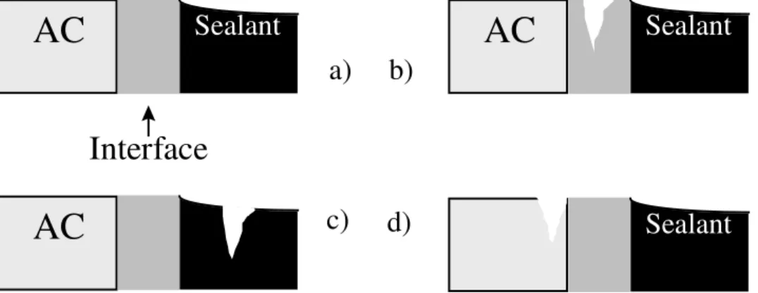
For maximum effectiveness, a sealant must remain firmly attached to AC at all times. As such, the performance of the sealant-AC joint is governed by the strength of the interface, the adequacy of the sealant and the integrity of the AC. The seal maintains its integrity in cold weather when the cohesive strength of the interface, i.e., adhesion, is equal to, or greater than, the tensile force due to the thermal contraction of the pavement (Figure 1a). The tensile stress at the interface is governed by the temperature [8], the geometry of the sealant [8,12,13] and its viscoelastic properties, as described by the storage (elastic) modulus and the loss (viscous) modulus [18]. The temperature dependent viscoelasticity of a bituminous sealant is a field that has received some attention [14] but remains largely unexplored. The magnitude of the tensile vector that plays on the interface thus remains unknown. The same is true of the effect of sealant composition on the rate of change in modulus and stress relaxation upon weathering, the extent of that change, and the service life that can be expected based on the aging properties.
Low temperature threshold values for the storage and loss moduli, necessary for improved sealant performance, have yet to be set. In accordance with the common adhesive failure in cold climates [5,6], it can only be said that tensile stress is greater in cold weather than in warm weather and that when it exceeds the cohesive strength of the
interface, sealant failure is adhesive (Figure 1b). When a sealant has weathered, it is often stiffer and shows slower stress relaxation than in its unweathered state. Tensile forces at the interface are higher and failure can be more rapid. In the case where the strength of the interface, i.e., adhesion, exceeds that of the sealant or that of the AC, the respective failures are in the sealant (Figure 1c) and in the AC (Figure 1d).
Interface
Sealant
AC
AC
Sealant
AC
Sealant
c)
d)
a)
b)
Figure 1: Three-phase sealant-interface-AC model of the system resulting from crack sealing in bituminous pavements. The interface is considered distinct from either the sealant or AC, although its thickness is in the micrometer range. The model shows an intact seal (a), adhesive failure (b), and cohesive failures in the sealant (c) and AC (d). Sealant failure being most often adhesive, the interface is most often weaker than needed for acceptable performance in low temperatures. To improve seal performance, a stronger interface, combined with sound AC on one side, and a sealant with appropriate rheological properties on the other is needed. Earlier, Panek [19] and Bikerman [20] had stressed the importance of the (polymeric) sealant-substrate interface, and in particular, the effect surface heterogeneity and contamination, surface wetting and material interlocking. These issues have yet to be addressed in any detail for bituminous sealants.
3.1 Adhesion at the interface
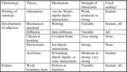
Several mechanisms have been used to explain the adhesion between materials [21-23]. Although they overlap to some extent, the mechanisms can be ordered chronologically, i.e., according to the rate at which they occur in crack sealing (Table 1). Individual mechanisms can be related either to the properties and preparation of the sealant, or that of AC. Sometimes, they can be related to both.
3.1.1 Adsorption theory
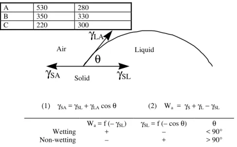
The theory can be applied to the vast majority of adhesion and adsorption phenomena of liquids onto solids. It describes wetting phenomena and is based on the measurement of the contact angle between a liquid and a solid (Figure 2). When a drop of liquid, say, a hot sealant, is placed onto a solid surface such as an aggregate, it remains stationary (contact angle > 90°) or it spreads (contact angle < 90°). If it spreads, the surface of the
solid is wetted properly and adhesion between the liquid and the solid is likely to be high. If, on the other hand, the liquid does not spread, then adhesion is lower. Wetting of an adhesive liquid onto the substrate is thus the first step in obtaining adhesion.
Wetting is governed by the attraction forces between the solid surface and the liquid [24]. The chemical forces can be weak (van de Waals forces) or moderately strong to weak (dipole-dipole interactions). Sealant and AC composition thus partly determine the adhesion strength. Consequently, sealants may be compatible with AC aggregates at one site and incompatible with that at another if the aggregates differ much. Very little work has been done on the wetting of aggregates by bitumen [25] or on the related adhesion of sealants to various aggregates (Table 2). A greater understanding of the effect of sealant formulation on wetting propensity is required to maximize sealant-aggregate compatibility. In this regard, the presence of recycled rubber filler particles in sealant may be particularly important. The filler may well prevent the extensive wetting of AC by the sealant (Figure 3). In this respect, it would be beneficial to measure the effect of filler concentration and particle size on adhesion, if any.
Table 1: Adhesion theories and their application to crack sealing with bituminous sealant
Chronology Theory Mechanism Strength of
interaction Cracksealing* Wetting of
substrate Adsorption van der Waals,dipole-dipole interactions Weak, moderate to strong Sealant Development
of adhesion Mechanicalinterlock Wetting Variable Sealant, AC
Diffusion Inter-diffusion Variable AC
Chemical
bonding Covalent bond Very strong None
Electrostatic Ion-dipole
interactions Strong None
Acid-base H-bonding, dipole-dipole, or ionic interactions Moderate to strong; very strong Sealant Failure Weak
boundary layer Defects atinterface Variable Sealant, AC *Most important element as related to the adhesion mechanism.
Table 2: Adhesion strength of sealants to aggregates [26] Sealant Adhesion strength (J/m2
)
A 530 280 B 350 330 C 220 300 Air Solid Liquid (1) γSA = γSL+γLA cos θ (2) Wa = γS+γL−γSL Wa = f (– γSL) γSL = f (– cos θ) θ Wetting + – < 90° Non-wetting – + > 90°
Figure 2: The contact angle, θ, of a liquid onto a solid. The contact angle is governed by the forces at the solid (S) – liquid (L), solid (S) – air (A), and liquid (L) – air (A) interfaces. By equating the horizontal components of these forces, or surface tensions (γij), equation (1) is obtained. The work of adhesion, Wa, is calculated with equation (2).
Wetting and non-wetting liquids show a positive and a negative work of adhesion, respectively.
Figure 3: Polished surface of two crack sealants (the one on the left contains little, if any
γ
SLγ
SAθ
γ
LArubber filler whereas that on the right contains recycled rubber particles that appear like aggregates).
3.1.2 Mechanical interlock theory
After an initial rapid wetting, the filling of microvoids by the liquid takes place, followed by its solidification [27]. This mechanistic approach describes the adhesion to a porous substrate. The resulting interlocking combines the cohesive strength of both individual solids to form an interface that acts as a composite material with properties intermediate to those of each material surfaces. Such a lock and key mechanism of bonding can explain the good resistance of some bonds to water damage. When a chemical reaction between the materials also takes place, as described later, an even stronger interface is created.
Interlocking, the filling of microvoids, is strongly affected by viscosity. Sealant viscosity varying from 6 to 70 Pa•s at typical application temperatures [16]. Not all sealant show
the same propensity for interlocking. Provided that wetting and interaction between sealant and AC takes place, sealants with low application viscosities will penetrate deeper in AC, fill voids and better follow the surface irregularities than a sealant of high viscosity (Figure 4).
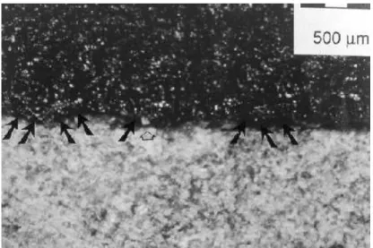
Figure 4: Magnified view of the interface between an aggregate and a sealant of high viscosity (70 Pa•s). The sealant surface, in black, is made visible by the reflecting light
(white specs). Voids at the surface do not reflect light and show as dark non-reflecting patches (black arrows). The white arrow points to a piece of aggregate caught in the void. Below 90 Pa•s a liquid can wet and fill 0.1 mm deep microvoids within 5 minutes, but the
cooling rate, i.e., the rate of viscosity increase after pouring, could thus have a significant effect on adhesion. In many Canadian cities, crack sealing is allowed when air temperature is down to 7°C. The effect of recycled rubber particles, mentioned earlier, is also significant in this regard, as these particles may adversely affect flow of sealant into microvoids.
Low sealant viscosities thus promote greater interfacial strength. Thus, for two bituminous sealants with identical suggested application temperatures, the one with the lower viscosity should be preferred. Note, however, that for a sealant of high viscosity at, say, 180°C, a lowering of the viscosity brought about by an increase in application temperature to, say, 200°C is not recommended. High temperatures can cause rapid sealant degradation [16]. It should also be considered that low viscosities are often a sign of low elastomer or recycled rubber content in the sealant formulation. This low elastomer content may compromise the resistance of sealant to flow at 40-70°C under pressure from tires and, in sub-zero temperatures, reduce elongation. Thus a bottom application viscosity limit should be set to insure satisfactory physical properties in service, and an upper viscosity limit should be set to insure sufficient sealant penetration into AC.
3.1.3 Diffusion theory
This theory explains the adhesion of rubbery and highly viscous materials. It asserts that bonding is the result of the entanglement of long chain compounds across the interface after materials have inter-diffused into one another. Close in concept to the mechanical interlock theory, the diffusion theory is the rationale for the heating of pavement cracks prior to sealing. The heating implies the inter-diffusion of two highly viscous media, the softened AC binder and the hot sealant. To this end, a hot-air lance is often used to heat cracks [28,29], but recent work has demonstrated that in normal use the hot-air lance does not soften AC long enough to promote adhesion [26]. Hence, interdiffusion of AC binder and sealant is probably not the dominant mechanism of adhesion between sealant and AC.
3.1.4 Chemical bonding theory
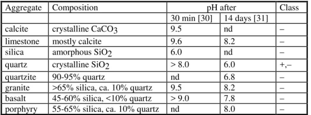
According to this theory a chemical reaction between two materials coming into contact is responsible for adhesion. The reaction produces a bond that cannot be broken without damaging the bulk of either joined materials (e.g., Figure 1, c and d), but this is not generally the case for bituminous sealants. This is because neither the bitumen, the polymer, nor the recycled rubber in the sealant react with aggregate or bitumen binder at the AC surface. As seen earlier, the sealant simply wets and adsorbs onto the AC surface. To use chemical bonding advantageously, and to obtain the strongest bond between sealant and AC, a primer would be necessary. For an effective exploitation of a primer, it must firstly react with AC upon its application, and in particular with aggregates, which are most often negatively charged oxides (Table 3). Secondly, the primer must react with the poured sealant. As far as the authors know, however, such primers have yet to be developed or used.
Table 3: Equilibrium pH of water in contact with aggregates and the resulting classification of aggregates*
Aggregate Composition pH after Class
30 min [30] 14 days [31]
calcite crystalline CaCO3 9.5 nd –
limestone mostly calcite 9.6 8.2 –
silica amorphous SiO2 6.0 nd –
quartz crystalline SiO2 > 8.0 6.0 +,–
quartzite 90-95% quartz nd 6.8 –
granite >65% silica, ca. 10% quartz 9.5 8.2 –
basalt 45-60% silica, <10% quartz > 9.0 7.8 –
porphyry 55-65% silica, ca. 10% quartz nd 8.0 –
*: –, alkaline; +, acidic; nd: not determined
3.1.5 Electrostatic theory
This theory postulates that adhesion arises from the interaction of point charges, positive and negative, on either side of an interface, where on one side there is a solid, and on the other an electric double layer composed of solvated ions and counter-ions. This model finds much application in colloid science [32], but it has found little practical use in engineering because of the large number of parameters it requires for predicting adhesion. In an early use of this theory, Sherwood [33] could not successfully predict the strength of the bitumen-aggregate bond. A variation of the model was used by Ensley [34] in an attempt to explain the interaction of bitumen around aggregates, but such ordering was later disproved [35]. The absence, or rarity, of point charges in bitumen possibly explains why other adhesion mechanisms predominate.
3.1.6 Acid-base theory
According to this theory, adhesion results from the polar attraction of Lewis acids and bases [36], i.e., electron poor and electron rich elements, at the interface. Acid-base interactions play an important role in the adhesion of bituminous materials as they control the compatibility of emulsions and aggregates, and can insure the wetting of the surface [37]. In the case of a cationic emulsion, for example, the latter would ‘set’ or ‘break’ upon contact with negatively charged aggregates such as those listed in Table 3. The adhesion strength provided by acid-base interactions is second only to that obtained by chemical bonding (Table 1). The advantage of the relatively strong acid-base interaction over the chemical bond, however, is that it can be obtained without resorting
to a primer: a sealant containing, for example, a Lewis acid (electron poor compound) could be poured over AC, which contains negatively charged (electron rich) aggregates. This possibility is not exploited, however. Existing sealants are relatively non-polar, neutral, and there is little to suggest that adhesion between sealant and aggregate relies on acid-base interactions. The little polarity that a sealant may possess is related to the composition of its bitumen, which contains saturates, aromatics, resins and asphaltenes [38-40], collectively called the SARAs (Figure 5). The polarity of these fractions increases in the order saturates < aromatics < resins < asphaltenes as their respective contents of oxygen, nitrogen, and sulfur increase. Hence, bitumen with high polarity and good adhesion potential based on acid-base interactions, would also have a high asphaltenes and resins content. Such a composition, however, would increase brittleness, an undesirable characteristic for a sealant. It follows that an improvement in the capability of acid-base interactions, and greater adhesion potential, must come from a sealant component other than bitumen. A polymer can provide the added polarity. This polymer must be such that it can interact with the negatively charged oxides found on the aggregate surface. N S N OH S S S
Bitumen
aromatics
asphaltenes
saturates
(paraffins)
resins
Figure 5: Composition of bitumen (adapted from [38-40]). Bitumen is fractionated by chromatography into four fractions. The saturates (S) are simple hydrocarbons of relatively low molecular weight. The polarity of the fraction is therefore low. The aromatics fraction (A) is not as saturated with hydrogen as the saturate fraction (thus the name of the first fraction). It contains molecules with carbon-carbon double bonds and cyclic aromatic structures. The resins fraction (R) contains more cyclic structures than the aromatic fraction and in addition it possesses polar chemical groups bearing an oxygen, nitrogen or sulfur atom. The asphaltenes fraction (As) contains the most
complex molecules of bitumen. They have high molecular weight and high heteroatom contents.
3.1.7 Weak boundary layer theory
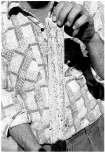
This theory does not explain why materials adhere to one another but rather why they debond. The theory suggests that rupture always takes place at the weakest link found at the interface between materials. In the practice of crack sealing, a weak interface can result from defects at the interface. These defects are possible loci of failures that arise because of poor wetting, and the presence of voids and dust at the interface. Figure 6 shows, for example, that imperfectly held fines invisible to the hand or eye can be detected at the surface of the rout with a strongly adhering tape.
Figure 6: Fines covering a strongly adhering tape as obtained in a rout after vacuum cleaning and slight heating and blowing with a hot-air lance [6].
Figure 7: Micro-cracks, as indicated by the arrows, in an aggregate of AC weathered two years in Ottawa, Canada. The defect can also be a microcrack introduced in the AC surface by a router (Figure 7). It can be expected that aged pavements would be especially sensitive to microcracking, and that the type of aggregate in the mix, the type of router used and the wear of its cutters would effect the microcrack density at the surface of routed cracks.
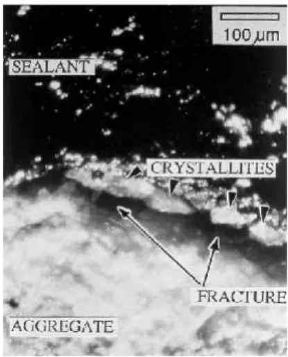
The microcracking of relatively young pavements is also of concern considering that microcracks propagate upon freezing and thawing [41,42] and reduce AC strength [19], which can lead to failure as illustrated in Figure 1d. Figure 8 shows how a microcrack can be a locus of failure when interfacial tension increases because of the crack opening induced by winter temperatures. The cracked aggregate can fracture further so as to leave crystallites attached to the sealant. In this case, failure is caused by a loss of cohesion in
the AC matrix adjacent to the rout surface, not by sealant debonding. On a larger scale, an entire aggregate may be pulled out of its bed by a sealant (Figure 9), much like the imperfectly held fines pulled out with tape.
Figure 8: Magnification of a cross-sectional rout showing the sealant/AC interface. The long arrows point to micro-cracks in aggregates. Upon widening of the crack in cold weather, the micro-crack widens and leaves crystallites (short arrows) attached to the sealant. As a result, the sealant is no longer adhering firmly to AC.
Figure 9: After micro-cracks have appeared at the aggregate-bituminous binder interface, aggregates can be pulled-out of their bed by a strongly adhering sealant.
4.
Conclusion
Mechanisms for adhesion have been reviewed and applied to the bituminous crack sealant/asphalt concrete (AC) system, which has been defined as a three-phase system comprised of the sealant, the AC and an interface. It was established that only two out of six mechanisms can explain the adhesion of bituminous sealant to AC. Initially, rapid adsorption, or wetting, of the AC surface by the sealant can occur, followed by the slow penetration of sealant into AC microvoids to provide interlocking. Adsorption is governed by the chemical interactions between sealant and AC, and consequently, it is sensitive to aggregate composition. The slow interlocking is controlled by sealant viscosity, and thus by pouring temperature and sealant cooling rate. Recycled rubber particles in sealants could also affect the adsorption and the interlocking processes. Sealant failure can be explained by another mechanism, the creation of a weak interfacial boundary between sealant and AC. The weak boundary is created by defects such as areas of poor AC wetting, voids, dust, and microcracks, that become the possible locus of
failure when the sealant is in tension. These defects are introduced at the interface, or avoided, during the preparation of the pavement cracks.
The review has also emphasized the following:
• the storage and loss moduli of bituminous sealants remain unknown;
• the rate of change in the moduli with weathering is undetermined;
• greater adhesion between sealant and AC could be obtained if two adhesion mechanisms were exploited, namely, chemical bonding and acid-base interactions. The resolution of a number of issues could therefore lead to improved sealant adhesion, and greater performance of the sealant-interface-AC system. Namely:
• acceptable viscoelastic profile at low temperatures, where tensile stress is maximum (0 to –40°C); at medium temperatures, where sealant flow under pressure by tires is of concern (40-70°C); at high temperatures (170-200°C), where application viscosity relates to wetting;
• mechanism and rate of sealant weathering, and related changes in moduli;
• factors that govern the microcracking of routed AC fissures;
• freeze-thaw and tensile resistance of interface containing microcracks;
• sealant and aggregate compatibility;
• effect of sealant microstructure, polymer and recycled rubber content on adhesion propensity.
5.
References
1. Eaton, R.A. and Ashcraft, J., ‘State-of-the-art Survey of Flexible Pavement Crack Sealing Procedures in the United States’, Report 92-18 (US Army Corps of Engineers, Cold Regions Research & Engineering Laboratory, Hanover, USA, 1992).
2. Anonymous, ‘Asphalt Pavement Repair Manuals of Practice’, Report SHRP-H-348 (Strategic Highway Research Program, National Research Council, Washington, District of Columbia, USA, 1993).
3. Chong, G.J. and Phang, W.A., ‘Improved preventive maintenance: sealing cracks in flexible pavements in cold regions’, Transportation Research Record 1205 (1988) 12-19.
4. Belangie, M.C. and Anderson, D.I., ‘Crack Sealing Methods and Materials for Flexible Pavements’, Report FHWA/UT-85/1 (US Department of Transportation, Washington, District of Columbia, USA, 1985).
5. Evers, R.C., ‘Evaluation of Crack Sealing Compounds for Asphaltic Pavements, Project No. 33’, Interim Report 3 (Ministry of Transportation and Communications of Ontario, Toronto, Canada, 1983).
6. Masson, J-F., Collins, P., and Légaré, P-P., ‘Performance of pavement crack sealants in cold urban conditions’, Canadian Journal of Civil Engineering 26 (1999), in print.
7. Zanzotto, L., ‘Laboratory Testing of Crack Sealing Materials for Flexible Pavements’ (Transportation Association of Canada, Ottawa, Canada, 1996). 8. Tons, E., ‘Geometry of simple joint seals under strain’, in ‘New Joint Sealants:
Criteria, Design, and Materials’, Publication No. 1006 (Building Research Institute, Washington, District of Columbia, USA, 1962) 41-61.
9. Castiff, E.H, Hoffman, R.F., and Kowalewski, R.T., ‘Predicting joint sealant performance by computer simulation, 1. Justification of method’, Journal of
Applied Polymer Science 14 (1970) 1143-1158.
10. Castiff, E.H, Hoffman, R.F., and Kowalewski, R.T., ‘Predicting joint sealant performance by computer simulation, 2. Results in simple extension and compression’, Journal of Applied Polymer Science 14 (1970) 1159-1178.
11. Castiff, E.H, Hoffman, R.F., and Kowalewski, R.T., ‘Predicting joint sealant performance by computer simulation, 3. Simulation of single and multi-step extension of a stress-relaxing material’, Journal of Applied Polymer Science 15 (1971) 1021-1028.
12. Khuri, M.F. and Tons, E., ‘Comparing rectangular and trapezoidal seals using the finite element method’, Transportation Research Record 1334 (1992) 25-37. 13. Wang, C.P. and Weisgerber, F.E., ‘Effects of seal geometry on adhesive stresses in
pavement joint seals’, Transportation Research Record 1392 (1993) 64-70. 14. Ketcham, S.A., ‘Sealants and Cold Regions Pavement Seals: A Review’, Report
95-11 (US Army Corps of Engineers, Cold Regions Research & Engineering Laboratory, Hanover, USA, 1995).
15. Ketcham, S.A., ‘Structural Mechanics Solutions for Butt Joint Seals in Cold Climates’, Report 96-10 (US Army Corps of Engineers, Cold Regions Research & Engineering Laboratory, Hanover, USA, 1996).
16. Masson, J-F., Lauzier, C., Collins, P., and Lacasse, M.A., ‘Sealant degradation during the crack sealing of pavements’, Journal of Materials in Civil Engineering
10 (1998) 250-255.
17. Masson, J-F., ‘Effective Sealing of Pavement Cracks in Cold Urban Environments’, Publication NRCC41098 (Institute for Research in Construction, National Research Council of Canada, Ottawa, Ontario, 1997).
18. Ferry, J.D., ‘Viscoelastic Properties of Polymers’ Third Edition (John Wiley & Sons, New York, USA, 1980).
19. Panek, J.R., ‘Causes of joint sealant failures’, in ‘ New Joint Sealants: Criteria, Design, and Materials’ (Building Research Institute, Washington, District of Columbia, USA, 1962) 74-80.
20. Bikerman, J.J., ‘Theory of adhesion for joint sealants’, in ‘ New Joint Sealants: Criteria, Design, and Materials’ (Building Research Institute, Washington, District of Columbia, USA, 1962) 35-39.
21. Wu, S., ‘Polymer Interface and Adhesion’ (Marcel Dekker, Inc., New York, USA, 1982).
22. Fowkes, F.M., ‘Role of acid-base interfacial bonding in adhesion’, Journal of
Adhesion Science and Technology 1 (1987) 7-27.
23. Good, R.J., ‘Contact angle, wetting, and adhesion: a critical review’, Journal of
24. Curtis, C.W., Ensley, K., and Hepps J., ‘Fundamental Properties of Asphalt-Aggregate Interactions Including Adhesion and Absorption’, Report SHRP-A-341 (Strategic Highway Research Program, National Research Council, Washington, District of Columbia, USA, 1993).
25. Ramon, G., ‘The static and dynamic aspect of adhesion’ (in French), Bulletin de
Liaison des Ponts et Chaussées V (1977) 13-21.
26. Masson, J-F. and Lacasse, M.A., ‘Effect of Hot-Air Lance on Crack Sealant Adhesion’, Journal of Transportation Engineering 125 (1999) 357-363.
27. Vakula V.L. and Pritykin, L.M., ‘Polymer Adhesion: Basic Physico-Chemical Principles’ (Ellis Horwood Ed., New York, 1991).
28. Knight, N.E., ‘Sealing cracks in bituminous overlays of rigid bases’,
Transportation Research Record 1041 (1985) 75-81.
29. Evers, R.C., ‘Evaluation of Crack Sealing Compounds for Asphaltic Pavements’, Project 33, Report 2 (Ministry of Transportation and Communications of Ontario, Toronto, Canada, 1981).
30. Williams, H.G., ‘pH determinations of water in contact with stones’, Journal of the
Society of Chemical Industry 62 (1943) 209-213.
31. Scott, J.A.N., Schellekens, J.C.A, Vonk, W.C., and Wilson. P.N., ‘A study of debonding and stripping mechanisms in road bitumen’ (in French), Bulletin de
Liaison des Ponts et Chaussées V (1977) 23-35.
32. Vold, R.D. and Vold. J.J., ‘Colloid and Interface Chemistry’ (Addison-Wesley, Reading, Massachusetts, USA, 1983).
33. Sherwood, W.C., ‘Determination of the Surface Charges of Certain Highway Aggregates by Streaming Potential Methods’, Report 24-1 (Virginia Highway Research Council, Virginia, USA, 1967).
34. Ensley, K., ‘A study of asphalt-aggregate interactions and asphalt molecular interactions by microcalorimetric methods: postulated interaction mechanism’,
Journal of the Institute of Petroleum 59 (1973) 279-289.
35. Jennings, P.W., Pribanic, J.A., Fanconi, B. and VanderHart, D.L, ‘Binder characterization and evaluation by nuclear magnetic resonance spectroscopy’, Report SHRP-A-335 (Strategic Highway Research Program, National Research Council, Washington, District of Columbia, USA, 1993).
36. Huheey, J.E., ‘Inorganic Chemistry: Principles of Structure and Reactivity’, Second Edition (Harper and Row, New York, USA, 1978) 258.
37. Anonymous, ‘Bitumen Emulsions’ (in French) (Union of the French Emulsion Producers, Paris, France, 1988).
38. Goodrich, J.L., Goodrich, J.E., and Kari, W.J., ‘Asphalt composition tests: Their application and relation to field performance’, Transportation Research Record
1096 (1985) 146-167.
39. Petersen, J.C., ‘Quantitative functional groups analysis of asphalts using differential infrared spectrometry and selective chemical reactions: Theory and application’,
Transportation Research Record 1096 (1986) 1-11.
40. Speight, J.G. and Moschopedis, S.E., ‘On the molecular nature of petroleum asphaltenes’, Advances in Chemistry Series 195 (1981) 1-15.
deterioration of concrete’, Proceedings of the Materials Research Society 370 (1995) 83-88.
42. Othman, A., Figueroa, L., and Aglan, H.I., ‘Fatigue behavior of SBS modified asphaltic mixtures exposed to low temperature cyclic aging’, Transportation
![Figure 5: Composition of bitumen (adapted from [38-40]). Bitumen is fractionated by chromatography into four fractions](https://thumb-eu.123doks.com/thumbv2/123doknet/14204626.480644/11.892.142.646.434.762/figure-composition-bitumen-adapted-bitumen-fractionated-chromatography-fractions.webp)