HAL Id: hal-03117484
https://hal.archives-ouvertes.fr/hal-03117484
Submitted on 21 Jan 2021
HAL is a multi-disciplinary open access
archive for the deposit and dissemination of
sci-entific research documents, whether they are
pub-lished or not. The documents may come from
teaching and research institutions in France or
abroad, or from public or private research centers.
L’archive ouverte pluridisciplinaire HAL, est
destinée au dépôt et à la diffusion de documents
scientifiques de niveau recherche, publiés ou non,
émanant des établissements d’enseignement et de
recherche français ou étrangers, des laboratoires
publics ou privés.
Particle approach to a stagnation point at a wall:
Viscous damping and collision dynamics
Qing Li, Micheline Abbas, Jeffrey F. Morris
To cite this version:
Qing Li, Micheline Abbas, Jeffrey F. Morris. Particle approach to a stagnation point at a wall: Viscous
damping and collision dynamics. Physical Review Fluids, American Physical Society, 2020, 5 (10),
pp.0. �10.1103/PhysRevFluids.5.104301�. �hal-03117484�
Any correspondence concerning this service should be sent
to the repository administrator:
tech-oatao@listes-diff.inp-toulouse.fr
This is an author’s version published in:
http://oatao.univ-toulouse.fr/27314
To cite this version: Li, Qing and Abbas, Micheline and Morris,
Jeffrey F. Particle approach to a stagnation point at a wall:
Viscous damping and collision dynamics. (2020) Physical
Review Fluids, 5 (10). ISSN 2469-990X
Official URL
DOI :
https://doi.org/10.1103/PhysRevFluids.5.104301
OATAO is an open access repository that collects the work of Toulouse
researchers and makes it freely available over the web where possible
and collision dynamics
Qing Li,1,2Micheline Abbas,1,2,*and Jeffrey F. Morris 3
1Laboratoire de Génie Chimique, Université de Toulouse, CNRS, INPT, UPS, Toulouse, France 2Fédération de Recherche FERMaT, Université de Toulouse, CNRS, INPT, UPS, Toulouse, France 3Benjamin Levich Institute and Department of Chemical Engineering, The City College of New York,
New York, New York 10031, USA
Highly resolved numerical simulations by the immersed boundary method are used to study neutrally buoyant spherical particle motion when carried by fluid approaching a wall. The carrying flow studied is the Hiemenz-Homann (HH) axisymmetric straining flow into
a stagnation point at a flat rigid wall, with a boundary layer of thickness 3δ = 3√ν/B, with
B the strain rate of the flow and ν the kinematic viscosity of the fluid. The pressure in the carrying flow
increases on approach to the stagnation point, as a result of the deceleration of the fluid. A single particle moving toward a smooth wall along the axis of the HH flow was studied by Li et al. [Li et al., . Results for the particle and fluid motion from this prior work are coupled here with numerical analysis of the impact using a simple model of roughness effects, with contact allowed at a radius slightly larger than the hydrodynamic radius, but with no detailed analysis of roughness otherwise considered. Solid contact is modeled for particle-wall separations below a threshold of order 1% of the particle radius, while the abruptly changing fluid flow during the collision is resolved numerically. The model is validated against existing experimental results of heavy particle settling and rebound, allowing for variation of the scale of the contact threshold. One particle impacting on the wall and two particles impacting each other as well as the wall are studied for neutrally buoyant particles in the stagnation point flow. Defining
the Reynolds number based on the particle radius a, Re = 2Ba2/ν = 2(a/δ)2, and the
Stokes number as St = Re/9, the influence of inertia is related to the particle size relative to the boundary layer thickness. For one particle of a/δ < 1, the particle asymptotically
comes to rest at the wall without rebound. Impact begins for a/δ ≈ 1.3–1.6 for particle roughness (onset of impact) from 6% to 4% of a, respectively, with progressively stronger
impact as a/δ increases beyond the threshold. The particle collision dynamics and the collision time deduced from this model are presented. For pairs of particles constrained to remain on the flow axis, a range of initial separations and sizes are studied. For the case when impact of the pair occurs before the closer particle reaches the wall, an impulse from the trailing particle to the leading one results in a much stronger collision than seen with a single particle, and multiple collisions are predicted to occur before the particles come to rest. A surprising contactless rebound of the particle closer to the wall is found, as the pressure variation associated with the carrying flow pushes this particle away from the wall while it is shielded from drag by the farther particle.
DOI: 10.1103/PhysRevFluids.5.104301
I. INTRODUCTION
Solid contact between freely moving particles immersed in a viscous fluid and a wall is of interest in many situations, the most common of them being impact-induced surface damage or erosion. Liquid mixtures impinging on an obstacle have rarely been considered, yet these are encountered in a number of applications, including slurry mixing with impellers [1], river transport of sand
past bridge pillars, or water ice-jet machining [2]. Slurry grinding in a ball mill [3,4] is another
application where the efficiency of the process depends on the mixture dynamics squeezed between moving obstacles (the grinding balls). On a different level, the interaction between a small number of flow-driven particles with a wall is the basis of particle sorting in microfluidic chips based on deterministic lateral displacement [5]. In such applications, the particle motion toward the wall is
driven by a flow with a strong wall-normal component.
The prediction of conditions that favor or prevent solid contact between moving surfaces requires understanding mechanics at different scales. To illustrate this, we consider the collision between a freely settling particle and a wall in a viscous fluid at rest. The breakdown of the fluid model, which predicts no contact for smooth surfaces, and the resulting impact in this settling problem have received significant attention. Experiments [6–11] and numerical simulations [12,13] agree
that a particle bounces from the wall if its inertia relative to viscous effects is sufficiently large. The relative influence of inertia depends on both particle and fluid properties and is commonly evaluated through the Stokes number St, which is the ratio between particle relaxation time and a fluid characteristic timescale (based on the particle size and settling velocity in this case). The particle experiences total viscous damping before reaching the wall at small inertia, whereas at intermediate St, it bounces back with partial energy loss due to hydrodynamic interaction. At very large St, viscous energy dissipation is negligible and the particle rebound is similar to the one that occurs in dry conditions given the same solid materials. Thus, in the settling problem, inertia controls the particle motion at a distance from the wall comparable to or smaller than the particle size. When the gap width between the particle and wall surfaces is reduced to a few percent of the particle radius, viscous resistance by the film squeezed in the gap results in a large local pressure that should grow as predicted by lubrication theory toward a divergence at contact provided that the surfaces are perfectly smooth. This would, in principle, prevent smooth surfaces from reaching contact. At high interstitial pressure, surfaces of finite-stiffness materials can deform before a bounceback motion is observed. The coupled fluid and deformable solid motion has been solved in the realm of the elastohydrodynamic theory [14]. However, surfaces are not perfectly
smooth, and once the gap between approaching surfaces becomes of the order of surface roughness, continuum fluid mechanics can break down in the gap, leading to solid contact. Smart and Leighton [15] used deviations of particle motion from predictions based on smooth surface lubrication theory to estimate the average roughness of micrometer-scale particle surfaces. Davis [16] found that surface roughness, represented by bumps at small surface coverage, has a negligible effect on the viscous lubrication until the gap between the smooth surfaces becomes equal to the size of the largest roughness element. At this point, the bumps make solid contact due to the discrete molecular nature of the fluid, potentially influenced by attractive London–van der Waals forces. The particle velocity subsequent to rebound seems to depend weakly on elastic material properties [9], but more
importantly on material plasticity [17] and on geometrical parameters of surface roughness [18]. The question of how solid contact takes place in a viscous fluid thus depends on both particle properties and surface features and may demand consideration of molecular physics in the fluid. Putting these issues aside, from a continuum perspective, collision is often viewed as an event of singular nature since momentum reversal takes place within a very short timescale compared to the characteristic timescale of particle motion (e.g., its relaxation time during settling). However, the actual wet contact timescale can be information of interest for applications. Prior studies [10,19]
have shown that when rebound occurs, the wet collision time is of the order of the solid contact timescale. However, around the onset of collision, the contact time and energy restitution are not yet rationalized. Their measurement seems to depend on microscopic surface details, as shown in the recent study by Birwa et al. [20].
(a) (b)
ω/B
P −P∞ P0−P∞z
z
3δ
r
r
FIG. 1. Axisymmetric Hiemenz-Homann [22,23] boundary-layer flow, transporting a neutrally buoyant particle of size finite compared to the boundary-layer thickness 3δ. (a) Vorticity contours. (b) Pressure contours, slightly perturbed by the particle. Note that the flow deceleration to match the nonpenetration condition at the wall leads to pressure rise near the stagnation point. Here P0and P∞denote the pressure at the stagnation point
at the wall and in the far field, respectively.
We develop a collision model similar to others noted, with the goal of studying the collision with the flow boundary by a particle moving under the influence of a carrying fluid flow, a phenomenon that has yet to be carefully examined. In the case studied here, the driving force that promotes surface approach is of hydrodynamic nature. In this paper we consider the collision with a wall of a particle driven by a flow that has a strong wall-normal component. Following our previous work [21], we consider the axisymmetric stagnation-point flow, which we term Hiemenz-Homann (HH) flow, recognizing the original work developing the boundary layer analysis by Hiemenz in the planar [22] and by Homann in the axisymmetric [23] versions of the pure fluid flow. This flow is represented in Fig.1, a configuration close to that encountered in impinging jets [24] and symmetricT-junction flows [25]. In that case, a boundary layer with thickness 3δ = 3√(ν/B) forms, where B is the characteristic strain rate of the wall-normal flow. Across this boundary layer, all velocity components decrease to zero to satisfy the no-slip condition at the wall. Fluid inertia at the particle scale is evaluated through the Reynolds number Re = 2Ba2/ν ≡ 2(a/δ)2. Particle inertia
is intrinsically related to the particle response time compared to the fluid characteristic timescale (here B−1), with the result that for a neutrally buoyant flow the Stokes number is proportional
to the Reynolds number, or more specifically St ∝ (ρp/ρf)(a/δ)2. In order to disentangle inertial
effects associated with particle density and size, we consider matched particle and fluid densities ρp= ρf, so that particle inertia results exclusively from particle size compared to the flow length
scale. Moreover, the particle motion is along the axis of symmetry of the flow, in order to focus on normal relative motion. A particle slightly shifted from the axis would lead to coupled normal and tangential interactions with the wall, a more complicated situation deferred to future work.
In Ref. [21] we considered particles in the size range 0.8 6 aδ 63.2 in the HH flow. There it was shown that far from the wall the particle decelerates as it approaches the wall and keeps a negligible slip velocity with respect to the fluid. As it moves forward through the boundary layer, the particle lags behind the fluid due to hydrodynamic interactions that tend to decelerate it before reaching the wall. As the separation distance to the wall decreases, two distinct evolutions of the slip velocity and hydrodynamic force are observed, depending on the particle size. A critical particle size acrit ≈ 2δ is found. For a < acrit, the particle is entirely immersed in the boundary layer, with the result that the
velocity and total hydrodynamic force experienced by the particle vanish monotonically as it asymp-totically approaches the stagnation point at the wall. However, for a > acrit, the slip is delayed until
the gap between the particle and the wall becomes small, leading to a much larger lubrication force and a nonmonotonic variation of the hydrodynamic force. Despite this tendency toward a divergence of the net hydrodynamic force as a/δ grows, the particle is decelerated inefficiently, so it carries a significant velocity while the separation gap width becomes of the order of 1% of the particle radius, suggesting that rebound due to solid contact with the wall might occur for realistic roughness.
In this study we address the later stage of the neutrally buoyant particle motion, allowing for particle-wall solid contact. This results in a rebound for a > acrit, where the particle carries
significant momentum upon approaching the wall. We investigate whether the particle bounce behavior is similar to that in the settling problem or differs due to the wall-normal carrying flow that provides the momentum in the case studied here. The particle and fluid equations of motion are solved numerically and coupled via the immersed boundary method (IBM). The grid resolution is fine enough in the gap region in order to avoid the need to complement the hydrodynamic force by subgrid modeling. The IBM used for this work does not take into account the surface deformation subsequent to pressure divergence inside the gap, nor does it consider nonsmooth surface profiles; thus we use a simple model with no detailed roughness analysis. A collision model is activated when the separation distance becomes less than a threshold distance ηa, where η is of order of a few percent. Although slightly larger in scale than in some experiments, this threshold gap is representative of characteristic microscopic surface imperfections of micrometer-scale particles, which can lead to solid contact as discussed above. Our approach in this study of particle-wall collision is similar to that of Ardekani and Rangel [12], who considered the settling problem.
Their numerical method is based on the distributed Lagrange multiplier to solve the particle-fluid interaction, combined with a solid-body collision model which estimates the particle velocity after collision while ensuring momentum conservation of the colliding system (particle-wall or particle pair). Their model neglects fluid effects during the collision process and is expected to be accurate if the collision time is smaller than the characteristic timescale of fluid motion by several orders of magnitude. However, it implies discontinuity of the particle velocity upon collision and therefore would induce numerical instability when combined with the IBM. Instead, we use the discrete element method with a finite solid stiffness. A spring force is applied to reverse, in a continuous way, the motion of overlapping solid surfaces within a short timescale after initial contact. The spring stiffness is connected to the Hertzian solid contact time that depends on solid properties and impact conditions.
The paper is organized as follows. In Sec. IIthe IBM is briefly outlined followed by a detailed explanation of the particle-wall collision model. Validations of the numerical method and collision model for the case of a settling particle in quiescent fluid are placed in an Appendix; this includes a discussion of the influence of the numerical parameters on the restitution coefficient and on the wet contact time relative to particle-wall collisions. Two sections are dedicated to the particle approach toward a stagnation point at a wall. Section IIIdiscusses the rebound dynamics of a single particle, as a sequel to our previous work [21]. The dependences of the rebound velocity and the wet contact time as functions of the particle size are the quantities of interest. Section IV considers the dynamics of a pair of particles constrained to the flow’s axis of symmetry as a first step to expand this study toward suspension flows. Interestingly, this section shows that while approaching a stagnation point, an unexpected contactless rebound leads to significant height of rebound of the pair away from the wall, a situation that apparently is specific to wall-normal flows.
II. NUMERICAL METHOD A. Fluid-particle interaction
The numerical method applied here to solve the particle-fluid interaction is based on the im-mersed boundary method [26]. The numerical implementation is explained in the work of Pierson
and Magnaudet [27]. The main information on the coupling between particle and flow equations of motion can be found in our previous work [21]. In summary, a force density FIBMis added to
the fluid momentum equation to enforce the no-slip boundary condition at the particle surface. This force density is prescribed in the form
FIBM= αρf
UD− U
τ , (1)
where U is the local fluid velocity, UD is the desired velocity in the solid volume (equal to the
particle velocity), ρf is the fluid density, and τ denotes a characteristic time which is set equal to
the time step in computational practice. The volume fraction α equals 1 in the solid and decreases to 0 in the surrounding fluid following a sine distribution within a spherical shell of thickness 31, where 1 denotes the local cell size [28]. The equation of motion of a neutrally buoyant particle is
ρpυp dV dt = d dt Z υp ρfU dυp− Z υp FIBMdυp+ Fc, (2)
where ρp and V are the particle density and velocity, respectively, and d/dt represents the time
derivative along the particle motion. The first and second terms on the right-hand side are the integral of the flow momentum and the force density inside the particle volume υp, respectively.
They represent the effect of hydrodynamic interaction on the particle motion. The last term Fc
(detailed below) is the force added to the particle equation of motion in case a collision takes place. It is equal to zero otherwise.
The way the fluid and particle motion are coupled together does not lead to discontinuity owing to the smooth interface representation. Usually, the time step of the fluid solver is a small fraction of the flow or particle relaxation timescales. In comparison, the particle-wall collision is a nearly singular event that leads to momentum exchange at a very short timescale. In standard simulations based on the immersed boundary method, the fluid-particle interactions are solved with several grid points per particle diameter (typically 10–20). When a pair of particles or a particle and a wall are close to contact, an additional contribution is added to compensate the underresolution of the viscous resistance in the thin gap between the surfaces [13,29–31]. If the particle inertia is large
enough, particle-particle or particle-wall collisions are taken into account by adding a contact force, inspired by the Hertzian contact theory where the force is a nonlinear function of the deformation or a linear model like the soft-sphere approach [32].
The simulations realized for the present work focus on the interaction between one or two particles approaching a stagnation point at a wall; in all cases we constrain motion to the line of symmetry of the axisymmetric flow. We aim to avoid as much as possible subgrid modeling of the hydrodynamic force while the particle approaches the wall. The fluid motion in the gap is very well resolved, using small time steps and a fine grid distribution, such that there is no need for additional lubrication forces, until the gap becomes small so that surface roughness can come into play, leading to collision. We do not consider the influence of roughness on the lubrication flow. This numerical approach is quite expensive for simulation of a suspension flow in general, but the cost is reasonable for study at the level of one or two particles as considered here. In the following, the collision model will be explained for the case of a single particle in contact with a wall. The model extension is straightforward to consider particle-particle collisions, as discussed in Sec. IV.
B. Collision model
In this work, we consider only small elastic deformation of the particle and wall upon contact. The theory of elasticity allows prediction of the stress distribution in the deformed region, as well as its radius and depth, and the particle-wall contact time, for a given particle size, density, and impact velocity. In the numerical simulations, in order to account for contact-induced particle-wall deformation, using nondeformable objects, we use the approach of Cundall and Strack [32]. This
method captures solid deformation during contact by a model allowing the overlap of nonde-formable objects. The description of this approach will be focused on particle-wall collision only in the wall-normal direction, as this is the only particle motion considered in this work. If the gap ζ = ZP− a (with ZPthe axial position of the particle center) is smaller than a given threshold ηa,
then a wall-normal contact force Fcis added to the particle equation of motion (2), with the force
modeled by Fc= − µ knζ + γn dζ dt ¶ . (3)
In the absence of viscous liquid (dry particle-wall collision), the parameters of the linear viscoelastic spring-dashpot system are determined by solving the particle deformation equation, which can be classified as a damped harmonic oscillator:
md
2ζ
dt2 + γn
dζ
dt + knζ = 0. (4)
The mass m is the equivalent mass of the binary system, which is equal to the particle mass in the case of particle-wall collision. Equation (4) is solved assuming that at the instant at which the collision begins (t = 0), ζ = 0 and dζ /dt = Vimpis the impact velocity. At the end of the collision
that lasts for a contact time Tc, the particle leaves the wall with a velocity dζ /dt = −edryVimp,
where edryis the normal restitution coefficient in the absence of viscous fluid. The system solution
leads to a relation between the spring-dashpot parameters and the colliding system properties γn=
−2mTc ln(edry) and kn=
mπ2
T2
c +
γ2
n
4m. The spring stiffness is a key parameter that should reflect the
material strength. Its relation to the contact time is different from the one found in elasticity theory, since the soft-sphere model assumes that the force varies linearly with ζ (instead of ζ3/2 in the
elasticity theory). The larger the value of kn, the more the objects behave like a rigid material, but the
smaller the time step should be in order to correctly solve the deformation equation. Nevertheless, it has been shown that the spring stiffness can be underestimated without significant impact on the dynamics of a granular system, for instance, on the collapse of a granular column [33].
In the case of particle-wall interaction mediated by a solvent, viscous dissipation influences the particle motion. A theoretical study of elastohydrodynamic particle-wall interaction was made by Davis et al. [14], in work that accounts for the viscous dissipation in the small gap between the particle and the wall, in addition to small elastic deformations in both the sphere and the wall. Their analysis assumes that the surfaces are perfectly smooth and that the particle does not come into physical contact with the wall because of the persistence of a liquid film between them. In the present study, we take into account the viscous dissipation by solving instantaneously the flow equation of motion in the whole domain (including the gap region) while the particle interacts with the wall. A contact force described by Eq. (3) is added to the particle equation of motion (2). The definition of the overlap ζ is slightly modified, ζ = ZP− a(1 + η), in order to avoid the overlap of
the immersed particle boundary with the wall, which would lead to numerical inconsistency in the hydrodynamic force computation. Since we are interested in situations where the energy dissipation in the solid material is negligible compared to the viscous energy dissipation in the fluid, we consider an elastic dry interaction edry= 1, and consequently the damping parameter γnis set to zero. The
spring stiffness is then
kn=
mπ2 T2
c
(5) and we are left with two parameters for the collisions: Tcand η.
C. Particle-wall contact time Tc
For a particle-wall collision in the gas phase, measurements have shown that the Hertzian model (see details in Ref. [34]) gives a good prediction of the collision timescale. According to the Hertzian
model, two contacting grains mechanically deform and the percussion force is proportional to ζ3/2, where ζ represents the grain deformation. The collision duration is expressed in terms of the particle materials [35] tHertz= 7.894 µ ρ2 p E∗2Vimp ¶0.2 a, (6)
where a and Vimpare the particle radius and impact velocity, respectively. The equivalent elasticity
of the particle-wall system E∗depends on the elastic modulus E and Poisson ratio ν of the particle
(subscript p) and wall (subscript w) as follows: E1∗ = 1 π( 1+ν2 p Ep + 1+ν2 w
Ew ). If all other parameters are
held constant, Eq. (6) indicates that tHertz increases with the particle size and decreases with the
particle impact velocity.
In the present paper, the contact time in the collision model is set to be a multiple of tHertz,
i.e., Tc= NctHertz. In this way, tHertz depends on the particle size and density that set the particle
inertia and the resulting impact velocity, while Ncallows us to tune the collision stiffness associated
with, for example, the solid elasticity. The elasticity is set to a constant value, large compared to the characteristic viscous stress. At the numerical level, low stiffness leads to large deformation, which is not appropriate for describing solids, whereas high stiffness leads to small deformation and therefore small time steps for the collision stage to be well resolved in time. When solid contact takes place in viscous liquid, the effective collision time is slightly longer but has the same order of magnitude as Tc, as will be shown in the following sections. When this collision time is sufficiently
small, we have confirmed through results not presented here that the jump in the velocity field, corresponding to the impulsive particle motion subsequent to particle-wall collision, is irrotational in the Hiemenz-Homann flow, like in the settling problem. Thus there is no jump in the vorticity field during the collision event. It takes a time longer than the collision timescale considered here for the produced vorticity to diffuse.
D. Surface roughness η
The threshold gap width ηa, below which the collision model is activated, can be thought of as a characteristic roughness scale of the surfaces that leads to solid contact. However, η simply defines a scale at which we begin to impose a contact force, with no detailed roughness considered. We consider η = O(0.01). The choice of this parameter influences the impact velocity at the onset of a collision during which motion reversal occurs: For other parameters held fixed, Vimp
increases as η increases. In reality, when the surfaces are rough, the presence of asperities reduces the effective surface of contact and slightly increases the contact time. The microscopic details associated with the bumps, including their stiffness, curvature, and size distribution, can influence the solid contact time, as can be inferred from a recent study [20]. These details are not accounted
for in the present simulations as the wall is perfectly smooth and the particle surface is defined using a smooth function distribution on the mesh. In all the results presented in this study, we checked
a posteriori that the amplitude of surface overlap ζ remains smaller than ηa. Indeed, numerical
overlapping of the surfaces can lead to spurious forcing induced by the immersed boundary method algorithm (while ensuring no slip at the particle surface), which can lead to overestimation of rebound velocities.
The validation of the numerical model has been carried out in a configuration well referenced in the literature, that of a particle settling in viscous fluid toward a solid wall. The velocity of the settling particle that experiences three consecutive stages, i.e., acceleration from rest, steady fall at terminal velocity, and deceleration near the wall, agrees quantitatively very well with experiments of Ten Cate et al. [8]. These results are included in Ref. [36]. Moreover, at small separation gaps
between the falling particle and the wall, numerical simulations were carefully compared to the experimental results of Mongruel et al. [6] (see [21]). The Appendix details the rebound velocity
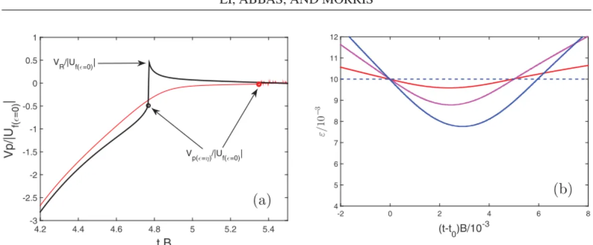
t B 4.2 4.4 4.6 4.8 5 5.2 5.4 Vp/|U f( =0) | -3 -2.5 -2 -1.5 -1 -0.5 0 0.5 1 VR/|Uf( =0)| Vp( =η)/|Uf( =0)| (t-t0)B/10-3 -2 0 2 4 6 8 ε/ 10 − 3 4 5 6 7 8 9 10 11 12 (a) (b)
FIG. 2. (a) Time evolution of the particle velocity as it approaches the wall on the axis of axisymmetric Hiemenz-Homann flow. The red and black lines correspond to a/δ = 1.6 and 3.2, respectively. (b) Evolution in time of the gap ǫ between the particle and wall surfaces. The red, pink, and blue lines correspond to a/δ = 2.4, 3.2, and 4.48, respectively. The collision parameters are Nc= 1 and η = 0.01.
III. PARTICLE-WALL COLLISION AT THE STAGNATION POINT
We consider a neutrally buoyant particle transported along the axis of symmetry of a wall-normal (Hiemenz-Homann) flow, as shown in Fig. 1. While the fluid flow decelerates to match
the nonpenetration condition at the wall, the pressure increases along the flow streamlines toward the stagnation point. The viscous boundary layer, in which the vorticity induced by the wall shear stress is confined, scales with δ = √ν/δ, where ν is the fluid kinematic viscosity and B is the strain rate of the flow into the wall. Far from the wall, the particle is carried by the flow with negligible motion relative to the fluid (slip), i.e., it behaves essentially as a tracer. As can be observed from Fig. 2, a slip with respect to the local fluid flow is observed when the gap between the particle surface and the wall becomes comparable to the particle radius a. The slip is a consequence of the particle’s finite size and rigidity. The dynamics depends significantly on a/δ, the particle size compared to the boundary-layer scaling. A transition in the behavior is observed at acrit/δ ≈ 2. From
the trajectories considered in Ref. [21], it was found that the slip is relatively strong for particle
radii a/δ = 0.8 and 1.6. While approaching the wall, these particles become fully immersed in the boundary layer. Indeed, the effective thickness of the boundary layer, above which the carrying flow velocity becomes negligibly different from linear, is 3δ. Hydrodynamic interaction with the wall decelerates these small particles efficiently such that the net hydrodynamic traction tends toward zero monotonically as the gap decreases, thus approaching the behavior in Stokes flow [37]. However, particles of a/δ = 2.4 and 3.2 are transported with negligible slip until they are closer to the wall. Since they are large compared to the boundary layer, they experience small hydrodynamic interaction with the wall until small gap widths are reached. When such a small gap is reached, the net hydrodynamic force grows rapidly due to lubrication and the slip increases significantly. Unlike the smallest particles whose motion is efficiently damped before reaching the wall, the largest particles become critically close to the flat wall while their velocity is not negligible, suggesting that, like in the settling problem, solid contact at finite velocity may occur for realistic roughness levels.
The numerical setup used to simulate the flow exploits the axisymmetry of the problem. The fluid velocity obeys the no-slip boundary condition at the wall. On the domain boundary parallel to the wall, the velocity is prescribed using the theoretical solution of axisymmetric Hiemenz-Homann flow. An outflow condition is imposed on the domain boundary parallel to the axis of symmetry. The domain size is Lz= 64δ and Lr= 32δ in the axial and radial directions, respectively. A single
far from the stagnation point and 1.6 × 10⁻⁵δ and 3.2 × 10⁻⁵δ near the stagnation point, in the
axial and radial directions, respectively. The ratio between the solid elastic stress and fluid viscous stress is set as E∗/µB = 1.25 × 10¹¹. This ratio corresponds roughly to poly(methyl methacrylate)
particles carried by a fluid whose viscosity is close to that of water and approaching a wall of the same material in a flow with a characteristic strain rate of approximately 150 s−1. The particle
radius is varied in the following range: a/δ = [1.3, 1.6, 1.9, 2.4, 2.5, 2.8, 3.2, 4.4, 5.7, 6.3]. The Reynolds number based on the strain rate, Re = 2Ba2/ν ≡ 2(a/δ)2, is in the range 3.4 6 Re 6
82. Particle inertia is intrinsically related to the particle relaxation timescale compared to the fluid characteristic timescale (here B−1), so the Stokes number of the neutrally buoyant particle is also
proportional to (a/δ)2. The particle rebound on the wall is studied while varying the effective surface roughness η. The collision stiffness is changed with Ncbeing set to 1 or 2. Note that the collision
stiffness is set through the choice of Ncin combination with the ratio E∗/µB = 1.25 × 10¹¹, which
is larger here than in the settling problem (in the Appendix). Larger elasticity leads to a stiffer collision (tHertz is smaller). This is compensated by slightly increasing Nc. The time step in most
of the simulations reported here is 8 × 10⁻⁵B−1. Several simulations were run with a time step of one-tenth this value in order to verify that the collision dynamics does not depend significantly on this numerical parameter. The collision event was solved with more than 100 time steps, a value determined a posteriori as in the settling problem.
A. Rebound velocity
Figure2(a)shows the typical evolution in time of the particle velocity during the approach to the stagnation point on the wall, for a/δ = 1.6 and 3.2. If a < acrit, as is the case for a/δ = 1.6, the
particle velocity vanishes while the gap width tends to zero. In contrast to this behavior, for a/δ = 3.2 the magnitude of the particle velocity is finite at ǫ = η and the particle experiences rebound with the wall. As in the settling problem, the particle motion reversal is very abrupt, approaching the singular response expected for rigid surfaces. The velocity upon rebound VR is equal to the
maximum particle velocity which is measured at the end of the collision process (when once again ǫ is larger than η) and whose sign is opposite to the sign of the incident velocity. To characterize energy restitution in the wall-normal flow, the particle rebound velocity is compared to a reference incident velocity. We choose to scale the rebound velocity by the unperturbed fluid velocity at a distance from the wall equal to a, or at ǫ = 0, denoting this by |Uf |ǫ=0|. Scaling the rebound
velocity by the fluid velocity at (almost) the position of the particle center upon contact with the wall results in a ratio that tends to unity if the particle experiences weak slip before impact. Figure 3
shows the evolution of the ratio VR/|Uf |ǫ=0| as a 2
function of (a/δ)2, which represents particle inertia
since both Re and St are proportional to (a/δ) . As the particle size increases, this figure shows clearly that the rebound velocity can become significant for a > acrit, the smallest size resulting in
particle collision with the wall. The dimensionless rebound velocity increases from 0 to approach 1 over two decades in (a/δ)2. The spanned range of (a/δ)2is similar to the range of Stokes numbers
considered in the settling problem. The data plotted in Fig. 3 suggest that the physics of particle-wall collision is globally similar in the two configurations. However, Fig. 3 shows that both the value of the rebound velocity and acrit depend strongly on the characteristic roughness η, much more
than is found in the settling problem for the same range of effective surface roughness. The value of acrit decreases when the roughness is increased, since the viscous damping of particle motion occurs at late stages during the particle approach to the wall, later than in the settling problem. The dependence of the rebound ratio on the collision stiffness is weak within the range of Ncstudied
here.
Figure 3(b) shows the rebound velocity as a function of the square of the particle size, when rescaled by acrit (which decreases when η increases). This scaling leads to a partial collapse of the rebound velocity curves obtained with different η, which suggests that the rebound velocity depends uniquely on the particle inertia compared to its inertia at the onset of collision. A similar observation is made in the settling problem [see the Appendix, Fig. 11(b)], in agreement with the
(a/δ)2 10-1 100 101 102 VR / |Uf |ε = 0 | 0 0.2 0.4 0.6 0.8 1 (a/acrit)2 10-1 100 101 102 VR / |Uf |ε = 0 | 0 0.2 0.4 0.6 0.8 1 (a) (b)
FIG. 3. (a) Rebound velocity as a function of the square of particle size, in Hiemenz boundary-layer flow. The rebound velocity is scaled by the fluid velocity at ǫ = 0 (which corresponds to z = a). The circles, triangles, squares, and diamonds refer, respectively, to simulations with η = 0.01, 0.02, 0.04, and 0.06. The closed and open symbols refer to Nc= 0.5 and 1, respectively. (b) Rebound velocity plotted as a function of
(a/acrit)2, where acritcorresponds to the particle radius at the onset of particle-wall collision.
work of Mongruel and Gondret [18]. These authors successfully modeled the restitution coefficient resulting from experiments of particle collisions with a textured wall, assuming that at intermediate Stokes numbers (characterizing particle inertia), energy dissipation is of viscous origin during particle deceleration and solid contact with the wall until the particle bounces back. This causes the effect of surface roughness on the rebound velocity to be merely lumped into setting the critical Stokes number. In HH flow, the collapse seems to apply in particular at the smallest roughness thresholds displayed here, i.e., η = 0.01 and 0.02. However, at η = 0.06, the velocity rebound is systematically larger than the rebound velocity at smaller η [see the pink points in Fig. 3(b)]. Indeed, as the colliding particles are large compared to the boundary-layer thickness, the viscous dissipation starts to be dominant only at small gaps (for instance, at ǫ < 0.1 for a/δ = 3.2 [21]). While the collision barrier is set at η = 0.06, the contribution of additional inertial effects to particle motion (like unsteadiness and inertial drag) is not yet negligible compared to the viscous dissipation and should be taken into account. Modeling of these other inertial effects is still an open question, as discussed in our previous work [21].
B. Collision time
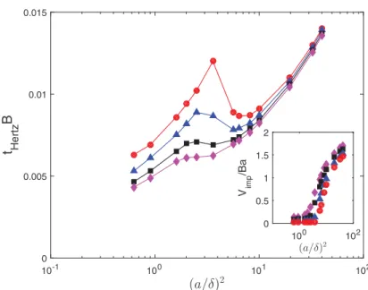
The evolution of ǫ as a function of time is shown in Fig.2(b)for different particle sizes. The particle-wall contact time in the HH stagnation point flow is obtained from the time signal of ǫ, while ǫ < η, as shown in Fig.2(b). It is then compared to the Hertzian timescale (6) on which the spring stiffness is built in the collision model (5). First, the Hertzian timescale is shown in Fig.4. It is two to three orders of magnitude smaller than the flow characteristic timescale B−1. This is
sufficiently small to allow representing the collision as a singular event. The dependence of tHertz
on the particle size is not monotonic, since tHertz∝ Vimp−0.2a, while the particle impact velocity Vimp
increases with the particle size, as shown in the inset of Fig.4. That figure shows that at η = 0.01, the smallest roughness used here tHertzfirst increases with the particle size up to a = acrit. In this case, it
seems that the velocity damping through the boundary layer, before touching the wall, is the leading contribution. This has no influence on the particle dynamics since the particle rests motionless at the wall. For a > acrit, the increase of tHertz with the particle size progressively prevails. The same trends
can be observed for η = 0.02, but are less evident for η = 0.04 and 0.06. For a given particle size, the Hertzian timescale decreases with the roughness, mainly because the impact velocity increases with η, the most important influence being observed around the onset to collision. Second, the wet
(a/δ)2 10-1 100 101 102 t Hertz B 0 0.005 0.01 0.015 (a/δ)2 100 102 V imp /Ba 0 0.5 1 1.5 2
FIG. 4. Hertzian contact time tHertzas a function of the square of the particle size, in Hiemenz-Homann
flow, at different collision onset η = 0.01 (circles), 0.02 (triangles), 0.04 (squares), and 0.06 (diamonds). The time is scaled by the inverse of the flow strain rate. The inset shows the evolution of the impact velocity scaled by Ba as a function of the square of the particle size.
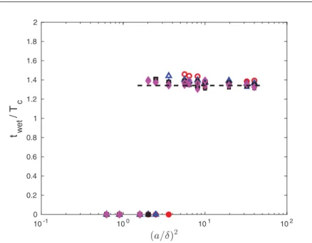
contact time in HH flow, scaled by the corresponding Hertzian timescale Tc= NctHertz, is shown
in Fig.5as a function of (a/δ)2. For a < a
crit, the particle motion is sufficiently damped that the
intensity of the rebound velocity is similar to the fluctuations of the spring model when the particle rests at the wall. The value of the collision time is then set to zero for a < acrit. At large particle
sizes, a finite contact time was measured, near 1.4 Tcfor different a and η, being just slightly longer
for larger η.
To give further insight into the value of the contact time during particle-wall collision in the HH flow, we can write a simplified force balance for the particle during the collision event. In addition to the collision force Fc[following Eq. (3)], the particle is subject to forces of hydrodynamic
origin. At the first level, viscous lubrication in the thin gap between the particle and wall surfaces is opposed to the particle approach toward (and departure from) the stagnation point. For a given particle velocity dζdt during the collision with the wall, the lubrication force can be approximated by FL= −6πµa1ǫdζdt, where flow inertia in the thin gap has negligible effect. The lubrication
contribution diverges when the gap width goes to zero, but this divergence is averted by the allowance for contact at a gap of the scale ηa. The drag from the main flow applies a force in the opposite direction, but it is much weaker compared to the viscous lubrication. At a second level, a particle accelerating in a liquid phase experiences a force due to the unsteady nature of the flow that can be written as FU = mfαdVdts, where Vs is the particle slip with respect to the unperturbed
flow and mf is the mass of the fictitious fluid that would occupy the sphere volume (here equal to
the particle mass owing to neutral buoyancy). There is no simple expression for the coefficient α as it depends on the flow inertia and on the particle position with respect to the wall. If the flow inertia at the particle scale is weak (small a/δ), α = O(1). For the differential acceleration, we have shown in previous work [21] that as ǫ → 0 the acceleration of the unperturbed fluid flow remains finite near the wall, whereas the particle acceleration diverges at small gap widths for a > acrit. Therefore,
we consider that the dominant unsteady contribution comes from the particle deceleration FU≈
−mfαd
2ζ
10-1 100 101 102 0 0.2 0.4 0.6 0.8 1 1.2 1.4 1.6 1.8 2 t wet / T c
FIG. 5. Wet contact time as a function of the square of particle size, in Hiemenz-Homann boundary-layer flow. The contact time is scaled by Tc= NctHertz. The circles, triangles, squares, and diamonds refer,
respec-tively, to simulations with η = 0.01, 0.02, 0.04, and 0.06. The closed and open symbols refer to Nc= 1 and 2,
respectively. The dashed line is an approximate theoretical value of twetfrom Eq. (7), considering α = 0.8 and
neglecting the viscous dissipation (therefore it does not depend on the particle size).
equation m∗d 2ζ dt2 + 6πµa 1 η dζ dt + knζ = 0, (7)
where m∗= mp+ αmf and it has been assumed in the lubrication force that the gap width ǫ remains
of the order of magnitude of the roughness η. At η = O(0.01), if the particle velocity is finite, the collision stiffness [estimated from Eq. (5)] is sufficiently large that the energy dissipation due to viscous lubrication in the gap has negligible effect on the contact time. Therefore, the contact time at the stagnation point can be approximated by twet ≈ π
q
m∗
kn. The value of m
∗depends on α, i.e., on
the unsteady hydrodynamic force experienced by the particle during the collision. Due to matched particle and fluid densities, if the coefficient α is O(1), the effective mass involved in the damped oscillator model is significantly increased compared to the particle mass in the collision model (4). This leads to twetbeing larger than the collision timescale Tcon which the collision stiffness is based.
From Fig.5it can be inferred that α depends weakly on the particle size in the range considered here.
We end this discussion by commenting on the threshold that corresponds to the transition between damped and bouncing particle dynamics. At the threshold, we expect that the particle reaches the wall (ǫ ≈ η) with small but finite velocity. At small impact velocity, the Hertzian contact time will diverge, and therefore the collision will be extremely soft. In this case, viscous lubrication can lead to a relatively long contact time, as suggested by the half period of the damped oscillator
twet= π q m∗ kn( 1 1−λ2/4knm∗) 1/2 , with λ = 6πµa/η.
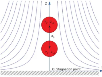
FIG. 6. Pair of particles approaching the stagnation point at the wall, along the axis of symmetry in Hiemenz-Homann flow.
IV. PAIR OF PARTICLES APPROACHING THE STAGNATION POINT
We consider the wall-normal approach of two freely moving spheres of equal radius toward the stagnation point along the axis of symmetry in the HH flow. Outside the boundary layer, the undisturbed fluid motion is comparable to that on the compressive axis of an unbounded extensional flow of strain rate B−1. In this linearly varying straining velocity field, a pair of particles is driven
toward close contact due to the relative velocity between their center positions. If inertial effects were negligible, hydrodynamic resistance would not allow the pair to experience contact, whereas inertial effects affect the pair interaction (hydrodynamic perturbation and solid contact). Moreover, the presence of the wall provides an additional constraint on the pair dynamics. Overall, the motion of the neutrally buoyant particles is expected to depend on their size compared to δ, with inertial effects stronger for larger particle size. When a/δ → 0, the particles are smoothly driven toward the stagnation point where they rest, in a manner similar to the single particle, one atop the other in the constrained motion along the axis of symmetry. When a/δ = O(1), relative motion causes solid contact to occur if roughness is considered, both between the particles and of the leading particle with the wall. Additionally, the pair motion will depend on the initial distance between the particles and with respect to the wall. As for the surface roughness that influences the dynamics at solid contact, we consider that both particles have the same characteristic roughness η and that the wall is perfectly smooth. Since the parameter space is quite large, the aim of this section is, without being exhaustive, to provide some insight into the unusual dynamics that the particle pair exhibits while approaching the stagnation point and following collision, limiting consideration to the slightly artificial case of motion constrained to the axis of symmetry.
Two initially motionless particles P1and P2are placed at the flow axis of symmetry as illustrated
in Fig.6. The simulation domain is similar to the one used to study the single-particle dynamics (Sec. III). The particles are released with a starting distance d0 between their centers. In the
following, the closest particle to the wall will be called P1and the farthest will be called P2. Being
closer to the wall, P1decelerates faster than P2. The collision between P1and the wall follows similar
considerations as described in Sec.III. In addition, when the gap between the surfaces of P1and P2
becomes smaller than 2ηa, a solid contact force is applied, following Eq. (3) described in Sec.II B, except that the mass m in Eq. (4) becomes equal to half of the particle mass and the equivalent elasticity in the Hertzian timescale (6) is given by 1 = 2(1+ν
2
p
E ). The grid spatial distribution is
E∗ π p
identical to the one used in Sec. III. In the near-wall region, where the collision events take
t B 3 4 5 6 7 8 9 10 11 12 , 1 , 2 1 2 3 4 5 6 7 3.5 4 4.5 0.1 0.2 0.3 0.4 0.5 0.6 0.7 0.8 1st bisphere contact particle-wall contact 3rd bisphere contact 2nd bisphere contact contactless rebound
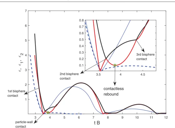
FIG. 7. Time evolution of the trajectories of P1 and P2 along the flow axis of symmetry. The red line
represents ǫ1= [ZPa1− 1], while the black line represents ǫ2= [ZPa2− 2(1 + η)]. The particle radius is a/δ =
3.2. The particles are initially located at ǫ1= 4 and ǫ2= 5.5. In comparison, the blue dashed and solid lines
represent the evolution in time of the gap width ǫ between the wall and the surface of a single particle of sizes
aand 2a located initially at ǫ = 4 and ǫ = 1.5, respectively. The starting times of the trajectories of the particle
pair and single particles were adjusted to match the instant of the first collisions with the wall.
P1and P2contain more than 200 and 150 grid points along their diameter, respectively. Using a grid
resolution twice finer did not significantly impact the pair dynamics.
Figure7shows the typical trajectory of particles P1 and P2of radius a/δ = 3.2. The radius has
been chosen larger than acritfor all η so that a single particle bounces back at the wall. The gap width
ǫ1= ZaP1 − 1 corresponds to dimensionless distance between the surface of P1and the wall (the red
line in Fig.7). The gap width ǫ2= ZaP2 − 2(1 + η) describes the separation of P2from the wall less
the distance at contact with P1when that particle contacts the wall (the black line in Fig. 7). Using
this notation, ǫ1= 0 occurs when the sphere P1 touches the wall, while ǫ2= 0 occurs when the
sphere surface P1is in contact with the wall on one side and with P2on the other side; it is important
to note that if the two spheres are in contact away from the wall ǫ2 = ǫ1 6= 0. The sequence of motion of the pair can be described as follows. First, P2 approaches P1 driven by their velocity difference in the straining flow. Thus P2overtakes P1, and when the gap width between their surfaces becomes
smaller than the roughness scale (ǫ2< 2η), the collision process is activated, leading to momentum
transfer from P2(being faster before the collision) to P1, which is then propelled toward the wall.
Second, P1 impacts the wall with a velocity strong enough that it bounces back. This is followed
by a second collision between P1 and P2, with the two having opposing velocities in this collision.
An unexpected event occurs afterward, at time t ≈ 3.9B−1 for this specific case as indicated in
Fig. 7 with a green circle. At that time, P1is lifted away from the wall, without having experienced
any solid contact with the wall. This contactless rebound occurs while the upward velocity of P2
is tending toward zero (since ǫ2 tends to a maximum near that time). Both particles experience a
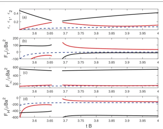
3.6 3.65 3.7 3.75 3.8 3.85 3.9 3.95 4 , 1 , 2 0.2 0.4 3.6 3.65 3.7 3.75 3.8 3.85 3.9 3.95 4 F T /µ Ba 2 -100 0 100 200 (a) (b) 3.6 3.65 3.7 3.75 3.8 3.85 3.9 3.95 4 F ∞ /µ Ba 2 200 400 600 t B 3.6 3.65 3.7 3.75 3.8 3.85 3.9 3.95 4 F H /µ Ba 2 -600 -400 -200 0 (c) (d)
FIG. 8. Time evolution of (a) ǫ1and ǫ2(taken from Fig.7), (b) the net force experienced by the particles,
(c) the contribution of the ambient pressure gradient, and (d) the remaining hydrodynamic contributions. The time is zoomed in around the contactless rebound event that occurs at t ≈ 3.9B−1. The red and black solid
lines represent P1and P2, respectively. The blue dashed line corresponds to a single particle that experienced
a collision with the wall, with the collision time adjusted to match t ≈ 3.9B−1. The force signals are removed
during the collision event.
rising) until the center of P2reaches a distance approximately 4a from the wall. The distance from
the wall reached by the pair during this motion is much larger than that reached by a single particle of radius a/δ = 3.2 colliding with the wall, which is ǫ ≈ 1.1a (the dashed blue line), but is more comparable to the postcollision distance (approximately equal to 5.8a) reached by a single particle of twice the radius (i.e., a/δ = 6.4, represented by the blue solid line in the figure). Thereafter, the particles are driven together again toward the wall, where they lose progressively their mechanical energy within a sequence of collisions until they rest one on the other at the wall.
The thrust given to P1and P2without any solid contact with the wall is of hydrodynamic nature
and can be explained qualitatively as follows. Near the time t ≈ 3.9B−1, the velocity of P2 rising
away from the wall (subsequent to the second rebound with P1) tends to become small before the
flow drives it back toward the wall. At that moment, P1being located downstream of P2with respect
to the incident flow is “protected” against the drag toward the wall that it would have experienced from the wall-normal flow in the absence of P2. Since the flow drag is largely reduced, the dominant
force contribution to P1 originates from the ambient pressure gradient established in the stagnation point region, which arises from the conversion of the fluid kinetic energy into pressure and is not significantly changed in the presence of the particle pair. For a particle relatively large compared to the boundary-layer thickness, this force can be evaluated as mfDU/Dt, where we recall that
mf is the mass of the fictitious fluid that would occupy the sphere volume and DU/Dt (the fluid
acceleration at the position of the particle center) is oriented from the wall toward the fluid (see Ref. [21] for more details). To support the above arguments, Fig. 8 shows the time evolution of the
have plotted the wall-normal component of the net hydrodynamic force equivalent to the surface traction FT computed directly from the numerical simulations, the force resulting from the ambient
pressure gradient F∞ = mfDUz/Dt and the difference FH = FT − F∞. The last contribution FH
represents the force due to hydrodynamic interactions, which are essentially associated with the drag experienced by the particle only near the wall (the slip is negligible away from the wall). Figure 8
shows that the net force FT is positive (it is approximately equal to 30 times the viscous force
scaling), while this force is negligible for P2 and the single particle, which both experience opposite drag and ambient pressure-gradient forces. Since P1and P2are close at that time, the upward force
applied on P1is transferred to P2as well. As the pair moves toward higher flow velocity, the negative
drag increases until a balance is reached between the drag and the pressure-gradient contributions. Afterward, the pair is then driven back toward the wall.
V. CONCLUSION
This paper has presented results supporting the understanding of the dynamics of neutrally buoyant particles approaching the stagnation point in a wall-normal flow. A motivation for this work was that it is a step toward identifying events that must be captured in the development of boundary conditions that need to be applied for continuum descriptions of liquid-solid mixture flows in general geometries. Density matching allowed uncoupling of inertial effects associated with particle size from those due to differential density. The motion of a single spherical particle and a pair of particles transported by the Hiemenz-Homann flow was numerically solved, with the fluid-particle coupling based on the immersed boundary method. A fine grid resolution was used in the thin gap region in order to fully resolve viscous lubrication flow between approaching and separating surfaces. If the gap width becomes smaller than a threshold ηa (modeling the asperity scale, but with no detailed roughness model), here taken from 1% to a few percent of the particle radius a, while the relative motion is finite, a spring force proportional to overlapping of nondeformable objects is added to model the collision event. The stiffness of this force is based on the collision timescale from the Hertzian theory related to material elasticity, particle density, size, and relative velocity. The model was validated by calculating the restitution coefficient and wet collision time in the case of a particle settling toward a wall in a quiescent viscous fluid. The results agree with previous experimental and numerical works.
Subsequent to the collision model development, the motion of a single neutrally buoyant particle was studied in Hiemenz-Homann flow as an archetype of wall-normal flows. The particle ap-proaches the stagnation point at the wall along the flow axis of symmetry. Particles small compared to the boundary layer thickness 3δ were found to slow down before reaching the wall, their motion being damped by hydrodynamic interaction with the wall when they become immersed in the boundary layer. However, for larger particles with radius a above a critical size acrit ≈ 2δ, the
particle starts to slip with respect to the local flow very late, once the separation gap width with the wall becomes small. Although viscous lubrication slows its motion, the gap width reaches critically small values while the particle velocity is finite. These particles bounce back at the wall. For a > acrit, the wet solid contact time and the particle rebound velocity were examined
as functions of particle inertia represented by (a/δ)2; we recall that both the particle-scale Reynolds
and Stokes numbers are proportional to (a/δ)2 in this flow. The onset of particle-wall collision
and rebound velocity depends significantly on the characteristic surface roughness η, whereas its effect on the collision time is weak. The overall increase of the rebound velocity with particle inertia is qualitatively similar to that observed in the settling problem. The essential difference is that the collision time depends weakly on the size (and thus inertia) of the neutrally buoyant particle. This has been interpreted based on the increase of the effective particle mass due to the unsteady hydrodynamic force experienced by the particle while approaching and departing from the stagnation point at the wall.
The near-wall dynamics of two equal spheres approaching the stagnation point was investigated as well. Small particles compared to the boundary-layer thickness (not shown in this paper) are
driven together by the flow, with their motion progressively decaying while approaching the wall. SectionIVshowed the typical dynamics of two larger particles approaching the stagnation point. A set of consecutive collisions takes place, while P1(the closest particle to the wall) experiences a
contactless rebound and is lifted together with the other particle P2away from the wall. The pair then
reaches a rebound distance much greater than the one reached by a single particle of the same size bouncing at the wall. We found that the contactless rebound occurs as a result of P1being sheltered
by P2 against the drag from the carrying flow. The thrust that lifts P1 is from the ambient pressure
gradient established in the wall-normal flow, which becomes the dominant hydrodynamic effect. This unusual particle dynamics highlights the rich interactions that may take place in a suspension flow near the stagnation point, a problem whose many-body extension will need to be studied to describe suspension dynamics in wall-normal flows.
ACKNOWLEDGMENTS
The authors thank A. Pedrono for her technical support in the development of the in-house codeJADIMand E. Climent and J. Magnaudet for discussions about the results. The computational resources were provided by the scientific group CALMIP under Project No. P1002, the contributions of which are gratefully acknowledged. This study was supported by the NEMESIS Chair (From the Nanoscale to Eulerian Modeling: Engineering and Science In Suspensions), a grant allocated by the Toulouse IDEX initiative to the FERMAT Federation.
APPENDIX: MODEL VALIDATION FOR THE SETTLING PROBLEM
A single solid sphere of density ρp and radius a, held at rest with its center initially located at
a distance ZP0= 58a from the wall, is allowed to fall under its weight. The particle is assumed to
fall along the axis of a cylindrical vessel of radius R = 24a and of length Lz= 60a. The cylinder is
entirely filled with a liquid of density ρf < ρp. An axisymmetric simulation domain is considered.
No-slip boundary conditions are imposed at the domain boundaries, except at the axis. The grid distribution is nonuniform in the radial and axial directions, with the mesh size varying between
a/20 far from the wall to 10−4aat the wall in order to correctly capture the viscous lubrication in
the thin gap when the sphere approaches the wall. The particle inertia is varied with the density ratio ρp/ρf ranging between 2 and 16 while the diameter is kept constant so that all the simulations can
be carried out within the same simulation domain.
A typical velocity signal is displayed in Fig. 9(a). The particle starts from rest far away from the wall and it relaxes toward a terminal velocity VT (seen as a plateau in the figure) over the
particle relaxation timescale. The terminal velocity is reached once the particle weight, corrected for buoyancy due to the liquid, is balanced by the drag. The Stokes number based on this terminal velocity, St = 19
ρp
ρfReT, ranges between 2 and 80, where the Reynolds number ReT =
2aVT
ν is based
on the terminal velocity. At the largest Stokes numbers studied (St = 58, 71, and 84), the axial distance required to reach the terminal velocity is longer than the domain length (60a). In these cases, the value of VT (on which the Stokes number is based) is chosen to be the maximum velocity
before the particle starts to decelerate near the wall. The ratio between the effective solid modulus of elasticity E∗ (considered constant) and the viscous stress is given by E∗/(µVT/a), which varies
between 1.5 × 10⁹ at the smallest Stokes number and 2 × 10⁸ at the largest. Two set
4s of numerica2l
simulations are performed, for Nc= 0.5 and 1. The time step is set between 5 × 10− and 5 × 10−
times the characteristic settling timescale (ts= 2a/VT) when the Stokes number is varied between 2
and 80. During the collision event, the time step was automatically decreased within the simulation to satisfy stability conditions. We verified a posteriori that the system dynamics was solved for at least ten time steps during the collision time, which scales like the Hertzian time (this is not known
a priori, at the beginning of a simulation, since the impact velocity is a result from the simulation).
When the distance between the particle and the wall becomes of O(a), hydrodynamic interactions lead to particle deceleration. At low St and Re, the wall-normal motion is damped before the
0 10 20 30 40 50 t/ts -1 -0.5 0 0.5 Vp/V T VR/VT -5 0 5 10 15 20 (t - t0)/ts 10-3 4 5 6 7 8 9 10 11 12 10 -3 (a) (b)
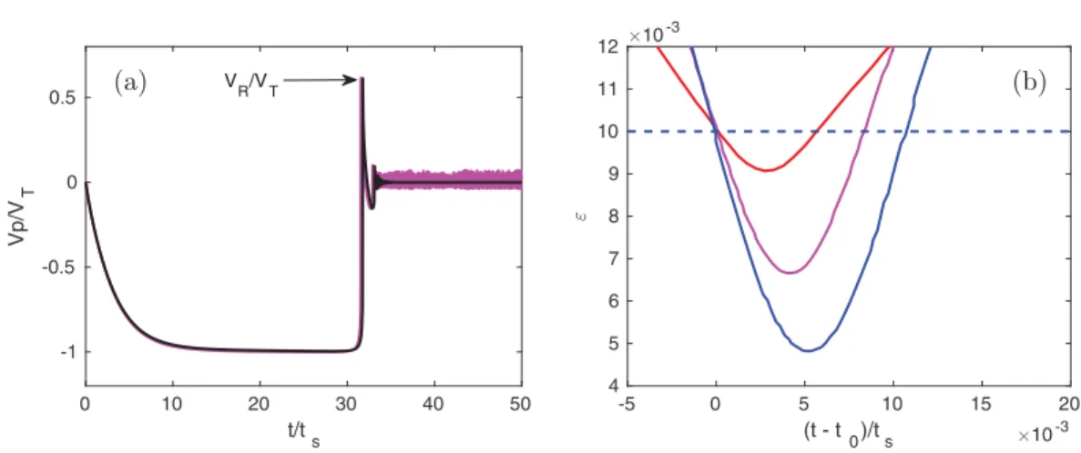
FIG. 9. (a) Time evolution of particle velocity at St = 9.9 in the settling problem. The pink and black lines correspond to simulations carried out with maximum imposed time steps dt = 2 × 10⁻²t
s and 2 × 10⁻³ts,
respectively, where ts= 2a/VT is the settling timescale. (b) Evolution in time of the dimensionless gap,
ǫ = Zp
a − 1, between the particle and wall surfaces for different particle inertia. The red, pink, and blue lines
correspond to St = 3.5, 9.9, and 16.8, respectively. The simulations were carried out with Nc= 1 and η = 0.01.
particle reaches the wall due to dominance of viscous resistance. Therefore, the particle velocity tends asymptotically to zero. However, if particle inertia is significant, the distance from the wall at which the particle starts to decelerate decreases with an increase of the Stokes number [9]. Viscous resistance is then not sufficient to damp the particle motion. Above a critical Stokes number, the gap width between the particle surface and the flat wall ǫ = Zp
a − 1 becomes smaller than the threshold
ηwhile the particle has significant velocity toward the wall (i.e., negative velocity in our reference frame); the collision model is then switched on to simulate particle rebound. The transition from viscous damping to collision is known to take place around a critical Stokes number Stcrit≈ 10 in
the settling problem. In our simulations, Stcrit is smaller than 10, as will be discussed below. In
Fig.9(a), the instant at which the collision occurs corresponds to a very abrupt jump in the velocity signal, as the particle velocity changes sign in a very short time as compared to the deceleration time before contact. The corresponding time evolution of the gap width ǫ (which obeys Vp= dǫ/dt) is
shown for different St in Fig.9(b). The evolution of ǫ is fairly symmetric while ǫ < η, indicating that viscous energy dissipation is weak during the collision process. The positive peak corresponding to the maximum velocity, VRin Fig.9(a), occurs at the end of the collision process, when the particle
bounces back. The nearly singular evolution of particle velocity is not sensitive to the time step provided the equations of motion are solved using more than ten time steps during the collision event. However, when the particle comes to rest, spurious fluctuations from the spring-dashpot model due to alternating overlapping and nonoverlapping states take place when the time step is not sufficiently small.
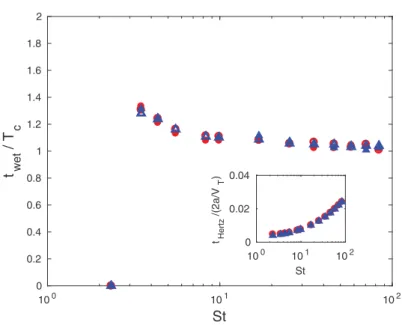
Above the critical Stokes number, a finite collision time is measured; this corresponds to the time interval in which ǫ < η. The collision time twet, scaled by Tc= NctHertz, is displayed as a
function of St in Fig. 10. The wet collision time decreases slightly as particle inertia increases. This is consistent with observations from experiments of Birwa et al. [20] and Chastel et al. [38]. In
the limit of high inertia, the contact time in liquid tends toward the dry Hertzian contact timescale, similar to the findings of Zenit and Hunt [19]. For Stokes numbers below Stcrit, the particle velocity
decays until the particle comes to rest at the wall. Numerically, the particle velocity exhibits small-amplitude fluctuations, again due to the spring model, which can be removed if the time step of the simulation is extremely small (see Fig. 9). In practice, the onset condition is a topic that requires
careful examination of fluid and solid mechanics during the collision process, involving details at the
![FIG. 1. Axisymmetric Hiemenz-Homann [22,23] boundary-layer flow, transporting a neutrally buoyant particle of size finite compared to the boundary-layer thickness 3δ](https://thumb-eu.123doks.com/thumbv2/123doknet/14272365.490533/5.892.159.743.199.453/axisymmetric-hiemenz-boundary-transporting-neutrally-particle-compared-thickness.webp)