Publisher’s version / Version de l'éditeur:
Vous avez des questions? Nous pouvons vous aider. Pour communiquer directement avec un auteur, consultez la
première page de la revue dans laquelle son article a été publié afin de trouver ses coordonnées. Si vous n’arrivez pas à les repérer, communiquez avec nous à [email protected].
Questions? Contact the NRC Publications Archive team at
[email protected]. If you wish to email the authors directly, please see the first page of the publication for their contact information.
https://publications-cnrc.canada.ca/fra/droits
L’accès à ce site Web et l’utilisation de son contenu sont assujettis aux conditions présentées dans le site LISEZ CES CONDITIONS ATTENTIVEMENT AVANT D’UTILISER CE SITE WEB.
Verification and Validation Data for Computational Unsteady Aerodynamics, pp.
361-382, 2001-10-01
READ THESE TERMS AND CONDITIONS CAREFULLY BEFORE USING THIS WEBSITE. https://nrc-publications.canada.ca/eng/copyright
NRC Publications Archive Record / Notice des Archives des publications du CNRC :
https://nrc-publications.canada.ca/eng/view/object/?id=c3e02e00-6c23-4646-be2c-035ad79f5ac2
https://publications-cnrc.canada.ca/fra/voir/objet/?id=c3e02e00-6c23-4646-be2c-035ad79f5ac2
NRC Publications Archive
Archives des publications du CNRC
This publication could be one of several versions: author’s original, accepted manuscript or the publisher’s version. / La version de cette publication peut être l’une des suivantes : la version prépublication de l’auteur, la version acceptée du manuscrit ou la version de l’éditeur.
Access and use of this website and the material on it are subject to the Terms and Conditions set forth at
Wing and fin buffet on the standard dynamics model
Defense Technical Information Center
Compilation Part Notice
ADPOI0722
TITLE: Wing and FIN Buffet on the Standard
Dynamics Model
DISTRIBUTION: Approved for public release, distribution unlimited
This paper is part of the following report:
ITLE: Verification and Validation Data for
Computational Unsteady Aerodynamics [Donnees de
verification et de valadation pour
l'aerodynamique instationnaire numeriquel
To order the complete compilation report, use: ADA390566
The component part is provided here to allow users access to individually authored sections
A proceedings, annals, symposia, ect. However, the component should be considered within
he context of the overall compilation report and not as a stand-alone technical report.
The following component part numbers comprise the compilation report:
ADPOI0704 thru. ADPOI0735
15E. WING AND FIN BUFFET ON THE STANDARD DYNAMICS MODEL
Reported by X. Z. Huangof work by S. Zan et al. IARINRC, Canada
INTRODUCTION
For modern aircraft with higher sweep angles flying at higher incidence, unsteady and burst vortex flow in the vicinity of the wing and downstream lifting surface lead to strong unsteady airloads and buffeting'. Thus, investigations were conducted in the Institute for Aerospace Research (IAR) Low Speed Wind Tunnel (LSWT)2
to study the buffet characteristics of the Standard Dynamics Model (SDM)3, a generic fighter aircraft configuration.
Since the spectrum of the aerodynamic input load is reasonably flat over the frequency range of interest, the solution to the equation of the motion is easily solved in the frequency domain for a given aerodynamic loads and vice versa. Following Jones4 and Mabey5, it is suggested that
4n7•7
is the best parameter to use as a measure of buffet excitation due to flow separations and unsteadiness and to denote this as the buffet excitation parameter.Buffeting is presented for three modes - the fin bending mode (VFB) and the wing symmetric and anti-symmetric bending modes (WSB and WAB)6. The strain gauges were mounted approximately on the node line of the torsional mode. It should be emphasized that since the model is rigid and the deformation of the structure and its damping are negligible, this measurement is linearly related to the buffet excitation. In addition, experimental results of static coefficients at angles of attack ranging from 00 to 90' are also included7
for the understanding of the flow behavior during the experiments.
The geometry of SDM is shown in Fig. 1. There are two SDM models with ratio of 0.375 (L and
SDM-S) used for buffet/dynamic stability and static experiments respectively.
The SDM model was sting-mounted in the wind tunnel8, which in turn was protruded from a strut cantilevered in the wind tunnel floor as shown in Fig. 2 and Fig. 3. The pitch angle is obtained by turning the strut through the center of the turntable. Sideslip angle setting is effected by banking the model about the body axis.
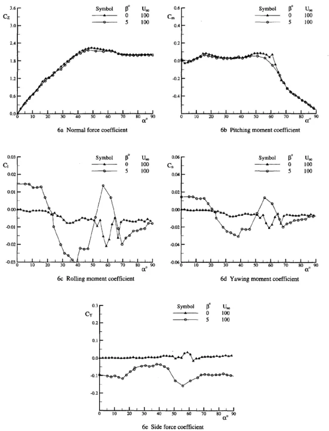
The flow visualization results show that at 3 = 00, separation becomes evident on the wing at cx t 4' in the case of strakes removed and a z 150 in the case of strakes installed. At cca ý 200, the vortex burst reaches the wing trailing edge while it breaks down completely over the wing at cca 29'. The onset of asymmetrical forebody vortices appears at a ; 400.
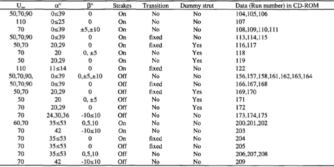
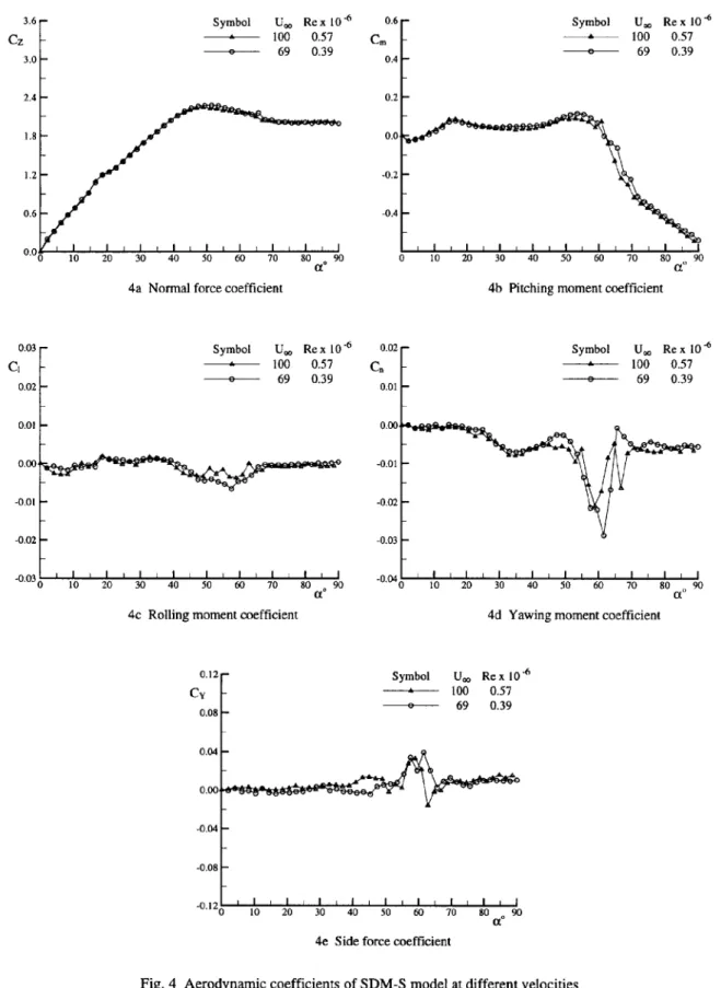
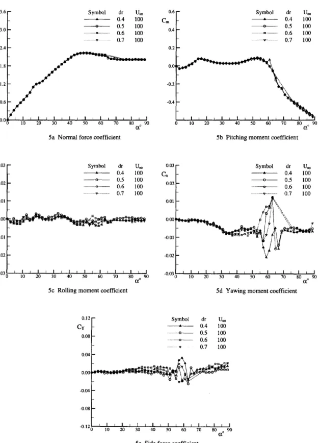
The test matrix for the buffet characteristics is presented in Table 1. The experimental results of static coefficients and buffet characteristics at different conditions are listed in Table 2 and Table 3 in the CD-ROM and illustrated from Fig. 4 to Fig. 6 and Fig. 10 to Fig. 14 respectively. The reference center for the moment is at 35% of MAC. The results with a dummy strut which was installed on the tunnel ceiling to investigate the asymmetrical effect of the strut are shown in Fig. 10 (cont.). In addition, Fig. 7 to Fig. 9 shows the shapes of different modes for the purpose of locating the strain gauges.
In general, the level of fin buffeting exceeds that of wing buffeting by an order of magnitude. In connecting with static measurements and flow visualizations this severe fin buffeting arises from the fact that the fin is immersed in the wake of the burst of strake and/or forebody vortices. The peak of fin buffet excitation is near an angle of attack corresponding to the onset of asymmetrical forebody flow. The magnitude of the wing buffet excitation parameter did not exceed 0.003, which arose from the interaction of the strake and wing vortices or simply from separated flow unsteadiness over the wing.
LIST OF SYMBOLS AND DEFINITIONS
B wingspan (in)c wing mean aerodynamic chord (MAC, m)
C, rolling moment coefficient (=t/qsB)
Cm pitching moment (=mrqs T)
Cn yawing moment (=n/qsB)
Cy side force coefficient (=Y/qs)
d body diameter at base (m)
dr ratio of diameters (=d/d)
dý sting diameter (m) f frequency (Hz)
fo modal frequency (Hz)
i, m, n rolling, pitching and yawing moment around body axes system
In mode generalized mass
n reduced frequency parameter (=f F /U-) n unsteady pressure fluctuations
n buffet excitation parameter due to flow separations and flow unsteadiness q free stream dynamic pressure (N/m2)
F(n) non-dimensional power spectral density of unsteady pressure fluctuations G(n) non-dimensional power spectral density of excitation
ReD Reynolds number based on ogive base diameter
SDM Standard Dynamics Model s wing area (m2)
Stks strakes
U. free-stream velocity (mn/sec) VFB vertical fin bending mode (376 Hz) WAB wing anti-symmetric bending mode (319 Hz) WSB wing symmetric bending mode (276 Hz)
X,Y,Z axial, side and normal force around body axes system OL angle of attack (deg)
3 angle of sideslip (deg)
0 amplitude (deg)
(T aerodynamic pitch angle (deg)
0• roll angle (deg)
t circular frequency (rad/sec)
FORMULARY
1
General Description of model
1.1 Designation Standard Dynamics Model (SDM)
1.2 Type Full model
1.3 Derivation F-16
1.4 Additional remarks Interchangeable strakes (LEX)
1.5 References Ref. 3
2
Model Geometry
2.1 Wing2.1.2 Aspect ratio 3.0 2.1.3 Dihedral angle 00 2.1.4 Leading edge sweep 400
2.1.5 Trailing edge sweep 00 2.1.6 Taper ratio 0.227
2.1.7 Twist 00
2.1.8 Wing centerline chord 0.3310 m (SDM-L)
2.1.9 Wing tip chord 0.0752 m (SDM-L)
2.1.10 Wing span 0.6096 m (SDM-L) 2.1.11 Mean aerodynamic chord 0.2299 in (SDM-L) 2.1.12 Area of planform 0.1238 m2 (SDM-L)
2.1.13 Form of wing-body junction With an interchangeable strakes (LEX) 2.1.14 Location of reference sections and Double wedged with 4.5% at the root chord
definition of profiles
2.1.15 Lofting procedure between reference Linear taper sections
2.1.16 Lead-edge bevel 150 on both sides
2.1.17 Trailing edge bevel 150 on both sides
2.1.18 LEX angle Double sweep back angles (730 and 830) 2.1.19 Form of wing tip Free stream aligned
2.2 Fuselage
2.2.1 Length 0.9429 m (SDM-L) 2.2.2 Diameter at base 0.1347 m (SDM-L) 2.2.3 Fineness ratio 7
2.2.4 Nose Tangent ogive
2.2.5 Fineness ratio of nose 3 2.2.6 Semi-apex angle of nose 18.920 2.3 Horizontal stabilizer
2.3.1 Planform Cropped delta wing 2.3.2 Aspect ratio 1.88
2.3.3 Taper ratio 0.2126 2.3.4 Dihedral angle -10°
2.3.5 Leading edge sweep 400 2.3.6 Trailing edge sweep 00 2.3.7 Lead-edge bevel 140
2.3.8 Trailing edge bevel 150
2.3.9 Twist 00
2.3.10 Full span 0.3548 m (SDM-L) 2.3.11 Area of planform 0.06697 m2 (SDM-L)
2.3.10 Centre line chord 0.1919 m (SDM-L) 2.3.12 Tip chord 0.0408 m (SDM-L)
2.3.13 Location of reference sections and Double wedged with 6.3% at the root chord definition of profiles
2.3.14 Lofting procedure between reference Linear taper sections
2.3.15 Form of stabilizer -body junction Fillet
2.3.16 Form of tip Free stream aligned 2.4 Vertical stabilizer
2.4.1 Planform Trapezoid 2.4.2 Taper ratio 0.53 2.4.3 Leading edge sweep 47.50 2.4.4 Trailing edge sweep 61.80
2.4.5 Twist 00
2.4.6 Height 0.1472 m (SDM-L) 2.4.7 Area of planform 0.01840 m2 (SDM-L) 2.4.8 Form of stabilizer -body junction Fillet
2.4.9 Form of tip Free stream aligned 2.5 Ventral fin
2.1 Platform Cropped trapezoid with LEX 2.2 Area of platform 0.003406 m2 (SDM-L) 2.3 Height 0.0481 m (SDM-L) 2.4 Leading-edge sweep 30'
2.5 Trailing edge sweep 00
2.6 Reference Detail drawings (Ref. 3) can be provided on the request
3
Wind Tunnel
3.1 Designation IAR 6ft x 9ft low speed wind tunnel
3.2 Type of tunnel Continuous atmospheric with closed return circuit 3.3 Test section dimensions Height: 6 ft, width: 9ft, length: 15 ft
3.4 Type of roof Solid with large optical quality plexiglass 3.5 Type of floor Solid with turn table
3.6 Type of side walls Solid with large optical quality plexiglass windows 3.7 Maximum speed 390 ft/sec
3.8 Contraction ratio 9
3.9 Support Sting attached to wind tunnel strut (see Fig. 2 and Fig. 3) 3.10 Turbulence in empty tunnel _< 0.12% at free stream speed of 100 ft/sec
3.11 Acoustic noise in working section _50.0028
3.12 Mean flow angularity :E0.10
3.13 Wind tunnel acoustic resonance The resonance of 416 and 475 Hz were eliminated before the buffet experiments
3.14 Velocity variation ±0.25% at free-stream speed of 27.4 m/s 3.15 Variation in total ad static pressure ±0.5% at free-stream speed of 27.4 m/s 3.16 References on tunnel Ref. 2
4
Model motion (SDM-L)
4.1 General description High natural frequency model mounted on the support with a large mass/low stiffness support
4.2 Model properties for three relevant modes
4.2.1 Generalised mass (grams) WSB=124, WAB=152, VFB=20.4 4.2.2 Characteristic area (min) WSB=0.083, WAB=0.083, VFB=0.01459
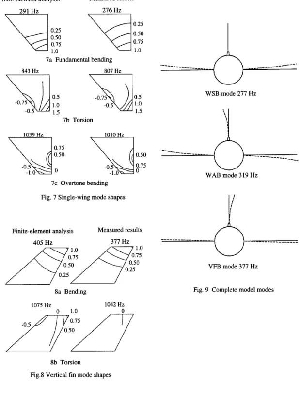
4.2.3 First bending frequency (Hz) WSB=276, WAB=3 19, VFB=377 4.3 Mode shapes
4.3.1 Single wing See Fig. 7 4.3.2 Vertical fin See Fig. 8 4.3.3 Complete model modes See Fig. 9
5
Test Conditions
5.1 Model planform area/tunnel area 0.0357 (SDM-L) 5.2 Model span/tunnel height 0.333 (SDM-L)
5.3 Blockage Function of angle of attack 5.4 Position of model in tunnel Standard side position
5.5 Range of velocities 25 m/s to 110 m/s for obtain different non-dimensional frequency. 5.6 Range of tunnel static pressure Close to atmospheric pressure
5.7 Range of tunnel total temperature Room temperature 5.8 Range of model steady or mean incidence 0' to 540
5.9 Definition of model incidence Angle between free-stream velocity vector and body axis in model's symmetric planforn plane.
5.10 Position of transition, if free N/A
5.11 Position and type of trip, if transition Two devices were used on the forebody: 1) A thin circumferential fixed ring of adhesive tape fixed around the nose approximately 1.5 cm from the apex. 2) Two strips of #80 grit with 1.5 mm wide located on the windward side of the forebody at 0=--40' extended from apex to within 2 cm of the intake
5.12 Flow instabilities during tests ±0.3 mis 5.13 Model deformations Negligible 5.14 References describing tests Ref. 6, 7, 8
6
Measurements and Observations
6.1 Steady pressures for the mean conditions Yes 6.2 Quasi-steady pressures
6.3 Unsteady pressures
6.4 Steady aerodynamic loads Yes
6.5 Dynamic derivatives Available but not included 6.6 Power spectral density of excitation Yes
6.7 Buffet excitation parameter Yes 6.8 Oscillation frequency Yes
6.9 Single wing mode shapes Yes (fundamental bending, torsion and overtone bending modes) 6.10 Fin mode shapes Yes (bending and torsion modes)
6.11 Complete model modes Yes (WSB, WAB and VFB modes) 6.12 Visualisation of surface flow Yes but not included
6.13 Comparisons between free and fixed Yes transition
6.14 Comparisons between strakes on and off Yes
7
Instrumentation
7.1 Steady loads (SDM-S)
7.1.1 Type of transducers Strain gauges.
7.1.2 Type of measuring system Six components balance (TASK balance) 7.1.3 Range of measuring system Forward normal force Z1=445 N
Aft normal force Z2--445 N Forward side force Y1=133 N Aft side force Y2=133 N Rolling moment L=5.65 N-m Axial force X=133N
7.1.4 Method of calibration Static calibration was performed on in situ in the wind tunnel 7.1.5 Principle and accuracy of calibration •1% of full-load output
including interaction and temperature effect
7.2 Buffet excitation measurement
7.2.1 Range of angle of attack 0° to 540
7.2.2 Type of analysis Measuring buffet excitation parameter, n obtained from the output of strain gauge bridges
7.2.3 Method of measurements Strain gauges mounted approximately on the node line of the torsional mode (about 74% root chord of the wing and 37% root chord of the vertical tail).
7.2.4 Method of acquiring and processing Four gauges near the leading-edge were used to detect the measurement about wing buffet symmetric bending mode and another four gauges aft were used to
detect the anti-symmetric bending mode.
7.2.5 Method of acquiring and processing Four gauges near the leading-edge to detect the fin bending mode. measurement about fin buffet
7.2.6 Sample rates 5500 Hz for the data channel of WSB mode and 7000 Hz for the channels of WAB and VFB modes
7.2.7 Windowing techniques A Hanning window was used
7.2.8 Frequency range over which analysis is WSB mode: 0.58<n<1.28; WAB mode: 0.66<n<1.47; valid VFB mode 0.96<n<1.73
7.2.9 A/D conversion details 12 bit A/D, 32k samples per condition, Anti-aliasing filters were used with a cut-off frequency of 2500 Hz for the WSB channel and 3500 Hz for the WAB and VFB channels
7.3 References on techniques See Ref. 6, 7
8
Data presentation
8&1 Test cases for which data could be made See Table 1 available
8.2 Test cases for which data are included in See Table I this document
8.3 Steady forces or moments See Fig. 4 to Fig. 6 and Table 2 in CD ROM 8.4 Quasi-steady or unsteady perturbation N/A
forces
8.5 Buffet excitation See Fig. 10 to Fig. 14 and Table 3 in CD ROM 8.6 Other forms in which data could be made N/A
available
9
Comments on data
9.1 Accuracy9.1.1 Mach number ±0.1% of set speed 9.1.2 Steady incidence ±0.010
9.1.3 Reduced frequency
9.1.4 Steady aerodynamic loads coefficients •1% of full-load output 9.2 Influence of tunnel total pressure Not examined 9.3 Effects on data of uncertainty, or
variation, in mode of model motion
9.4 Wall interference corrections Following standard procedures the dynamic pressure was corrected for solid blockage and corrections were applied to the angle of attack to account for upwash caused by the tunnel walls 9.5 Wake blockage corrections The correction to dynamic pressure due to wake blockage is •51%
and was not corrected for
9.6 Other relevant tests on same model Dummy strut tests was conducted and found the support interference effects were small
9.7 Relevant tests on other models of nominally the same shapes 9.8 Any remarks relevant to comparison
between experiment and theory
9.9 References on discussion of data Ref. 6, 7
10 Personal contact for further information
Xing Zhong Huang, Aerodynamics Laboratory, Institute for Aerospace Research, National Research Council of Canada Building M-10, 1500 Montreal Rd. Ottawa, Ontario, Canada. K1A 0R6
e-mail [email protected]
11 List of references
1. Edwards, J.W., "Unsteady Airloads Due to Separated Flow on Airfoils and Wings," AGARD-CP-483. 2. Brown, T.R., "Description of the 6 ft x 9 ft Low Speed Wind Tunnel," NRC, NAE LTR-LA-285, Nov. 1986. 3 Huang, X.Z,, "Standard Dynamics Model," T87-277-U, 1987.
4 Jones, J.G. "A Survey of the dynamic Analysis of Buffering and Related Phenomena," RAE TR 72197, 1973. 5 Mabey, D.G., "Some Aspect of Aircraft Dynamic Loads Due to Flow Separation," AGARD-R-750
6. Zan, S.J., "Measurements of Wing and Fin Buffeting on the Standard Dynamics Model," NRC No. 32158, IAR-AN-76, 1993.
7. Huang, X.Z. and Beyers, M.E., "Subsonic Aerodynamic Coefficients of the SDM at Angles of Attack up to 90°," NAE LTR-UA-93, 1990.
8. Hansen, K., "Installation of Models in the 6 ft x 9 ft Low Speed Wind Tunnel," NAE LTR-LA-286, Aug. 1986. Table I Test matrix of wing and fin buffet experiments (SDM-L)
U_ cx' D, Strakes Transition Dummy strut Data (Run number) in CD-ROM 50,70,90 0_•39 0 On No No 104,105,106 110 0<25 0 On No No 107 70 0!-39 ±5,±10 On No No 108,109,110,111 50,70,90 0_<39 0 On fixed No 113,114,115 50,70 20,29 0 On fixed Yes 116,117 70 20 0, ±5 On No Yes 118 50 20,29 0 On No Yes 119 110 11•514 0 On fixed No 122 50,70,90, 0_<39 0,±5,±l0 Off No No 156,157,158,161,162,163,164 50,70,90 0_<39 0 Off fixed No 166,167,168
50,70 20,29 0 Off fixed Yes 169,170
50 20 0, ±5 Off No Yes 171 70 20,29 0 Off No Yes 172 70 24,30,36 -10:510 Off No No 173,174,175 60,70 35<53 0,5,10 On No No 200,201,202 70 42 -10_•10 On No No 203 70 35_•53 0 On fixed No 204 70 35:g53 0 Off fixed No 205 70 35_•53 0,5,10 Off No No 206,207,208 70 42 -10_•10 Off No No 209
926T 0 9
.0 t
Crlj
TUNNEL CEILING 54.51 TUNNEL CENTRE-LINE TUNNEL FLOOR ... 0 5 12 SCALE (INCHES)
Fig 2 Side view of SDM-L model in the IAR 6 x 9 foot wind tunnel
II tV
--105.00
TURN TABLE CENTRE 22.13
0 6 12 SCALE (INCHES)
3.6 Symbol U. Rex 10.6 0.6 Symbol U. Rex 10-6 Cz - 100 0.57 Cm 100 0.57 3-e--- 69 0.39 OA-- 69 0.39 3.004 2.4 0.2 1.80. 1.2 -- 0.2 0 .6 -0 .OA4 0 10 20 30 40 50 60 70 800 (90 0 10 20 30 40 50 60 70 80 ,t 90 4a Normal force coefficient 4b Pitching moment coefficient
D.03 Symbol U. Rex 10.6 0.02 Symbol U. Re x 10-6
C 100 0.57 C- ---- 100 0.57 D.--- 69 0.39 --- 69 0.39 0.01 0.00 0.00, -0.01 -0.01 -0.02 -0.02 -- 0.03
-0.030 I LL I L iI L9I L iII I I -0.04 I i 1,,1 L I 1 I,1 1 0 10 20 30 40 50 60 70 80090 10 20 30 40 50 60 70 80,90
4c Rolling moment coefficient 4d Yawing moment coefficient
0.12 -Symbol Uý Rex 10.6
C 0 10200 0.57 --08--- - 69 0.39 0.048 0.00 -0.04 -0.08 .0 .1 2 1
0
10 l I 20 l I I 30 I 4l i l 4 50 i l 60 i 70 80 90 4e Side force coefficient3.6 Symbol dr U. 0.6 Symbol dr U-Cz -- --- 0.4 100 C. 0.4 100 3.0 -e--- 0.5 100 0.4-- 0.5 100 --- 0.6 100 0.6 100 . v 0.7 100 0.7 100 2.4 0.2 1.2 -- 0..2 0.6 -0.4 10 20 30 40 50 60 70 8 0 90 0 10 20 30 40 50 60 70 80 ,90
5a Normal force coefficient 5b Pitching moment coefficient
0.03 Symbol dr U- 0.03 - Symbol dr UW C 0.4 100 Cn 0.4 100 -- - 0.5 100 0e--- 0.5 100 0.020.6 lO0 0.02 0.6- 100 0.6 100 ... 0.7 .• ... 100 . .... -... 0.7 100 0.01 0.00.00 -0.01 -0.01 -0.* 02 -0.02 -0.03 I I I I I I I I -0.03 0 10 20 30 40 50 60 70 80 o 90 0 10 20 30 40 50 60 70 80 90
5c Rolling moment coefficient 5d Yawing moment coefficient
0.12 Symbol dr Uo Cy --- -. 0.4 100 08 - 0.5 100 0.080.6 100 , 0.7 100 0.04 0.00 -0.04 -0.08 -0.12 0 0 10 IL 2 20 I 30 I L 40 I 50 I I610 60 70 I 80 no90I I
5e Side force coefficient
3.6 Symbol 13 U. 0.6 Symbol U. Cz 0 100 Cm 0 10 30 ---- --- 5 100 0.4 5 100 2.4 012 1.800 1.2 -0.2• 0.6 -0.4 0 10 20 30 40 50 60 70 80 ( 90 0 10 20 30 40 50 60 70 80 90 6a Normal force coefficient 6b Pitching moment coefficient
0.03 - Symbol K3o U, 0.06 Symbol 13W U.
CI --- 0 100 C- - 0 100 -2---- 5 100 0.4--- 5 100 0,02
0.04
0
0.01 -0.02 0.00 0.00 -0.01 -0.02 -0.02 -0.04 S I , I , I t I I I I I -0-03"*0
-0.06 10 20 30 40 50 60 70 80 90 0 t0 20 30 40 50 60 70 80 90 6c Rolling moment coefficient 6d Yawing moment coefficient0.3 Symbol 30 U. Cy 0 10 0.2---- 5 100 0.2 0.0 -0.1 -0.2 0 10 20 30 40 50 60 70 80 90
6e Side force coefficient
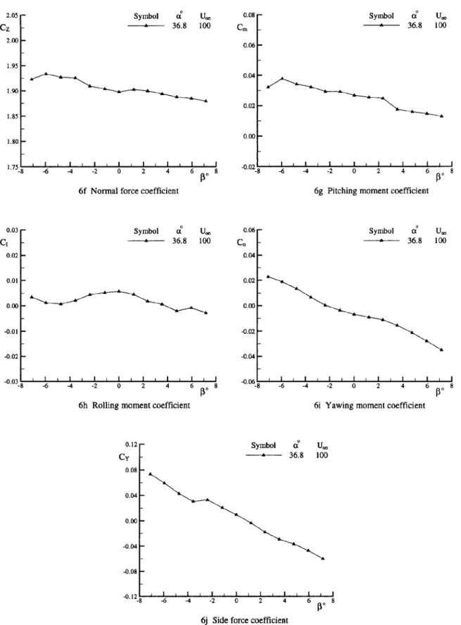
2.05 Symbol 0i U- 0.08 - Symbol I U-Cz - 36.8 100 C- 36.8 100 2.00fo6 0.06 1.95 0.04 1.90 0.02 1.85 0.00 1.800 175• 1-- I -6 I -4 -2 I I 0 I iI 2 I 4 I 6 I I 8 -02lI-8 -4 -2 0 2 4 6 8 72 4 010 11304 6
6f Normal force coefficient 6g Pitching moment coefficient
0.03 Symbol U 0.06 Symbol U_ CI ---- 36.8 100 C, - 36.8 100 0.02 0.04 0.01 0.02 0.001 0.00 -0.01 -0.02 -0.02 -0.04 -0.03I I I I -0.06
"-8
-6 -4 -2 0 2 4 6 8 -. 8 -6 -4 -2 0 2 4 6 8 130130
6h Rolling moment coefficient 6i Yawing moment coefficient
0.12 - Symbol CI Ua Cy - 36.8 100 0.08 0.04 0.00 --0.04 -0.08 -0.12 8 I I I I I i I -8 -6 -4 -2 0 2 4 6 8 6j Side force coefficient
Finite-element analysis Measured results 291 Hz 276 Hz 0.25 0.25 0.50 0.50 0.75 0.75 1.0 1.0 7a Fundamental bending 843 Hz 807 Hz 0.5 -0.75 0.5 WSB mode 277 Hz -0.75 1.0 -0.5 1.0 -0.5 1.5 1.5 7b Torsion 1039 Hz 1010 Hz 0.75 0.50 0.50 -0.5 -0. 0.75
"-1.0
-1.0 WAB mode 319 Hz 7c Overtone bendingFig. 7 Single-wing mode shapes I
Finite-element analysis Measured results
405 H z 377 Hz ...
1.0 1.0
0.75 0.75
0.50 0.25 VFB mode 377 Hz
8a Bending Fig. 9 Complete model modes
1075 Hz 1042 Hz 0 1.0 0 -0.5 0.75 0.50
z
7
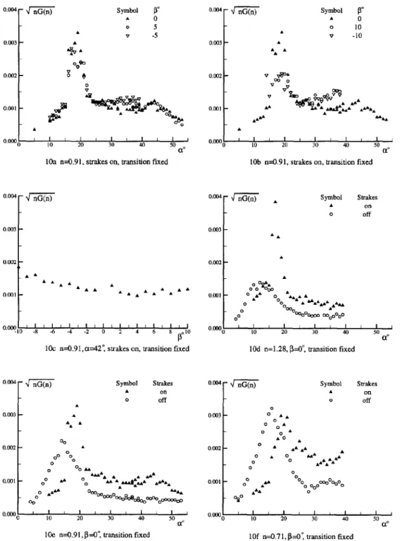
8b Torsion0.004 -nG(n) Symbol I° 0.004 - nGQn Symbol IV A 0 A 0 o 5 0 10 A v -5 A v -10 0.003 .A 0.003 A 19 A A A 0.002 - 0 0.002 V v 20 0 00 0 0 V v OV
0.001 "OOA26 0.001 A , AgA' AAA A,
0
I0000.000 0
0 10 20 30 14 0 a.8 0 10 20 30 40 I 0 1O0 n=O.91, strakes on, transition fixed lOb n=.291, strakes on, transition fixed
0.004 -" nG(n) Sy l a0.004 nG(n) A Symbol Strakes
A on 0 off 0.003 0.003 o 'A 0.002 - 0.002 A A AA o 0 o ••o 00 000
0.001 . 4 A° A" A Aat • I•
0,001 0° t " AA & &, &,A&AA°°O ooooo00
~~~~~~0
ooýi ... O0 DO..I G o • 4O 0 • 0 .t 0 - l I1I 0. )00 1 1 I 1 -I -I I I I -0 -H -6 -4-2 0 ' 4 0 0 0 20 30 40 50 C(10c n=0.91,=042", strkes on, transition fixed 10d n=1.28, =0-', transition fixed
0.004 Symbol Strates 0.rat4 Symbol StrDkes
A on A od 0 Off 0 off 0.003 A 0.03 0 A A AA A 0 00,0AA A.0 p0 .0 0 0 A AAA A ' "AA 0~~ 0 A -A o0 00A 0 A 0 A 0.00 , " 0 AI~AA. 0 AA 0,0AAA 0 0 AA 0 AA A AA OM -A A 0AAA00 A0
~oP%08-.
4 0 0.001 0 0 AA ' AL!-L I 0.000 10 ' 2 0 0.0o 10 20 30 40 50~ ~
0 10 2 30 40 50,i~e n=O.91,f3=0*, transition fixed 10f n=0.7 1, P=O', transition fixed
Fig. 10 Wing buffet excitation parameter of SDM-L model at different conditions (WSB mode)
0.004 - nG~n 0.004
4
nG(n) Symbol Strakes Dummy strut 0. on not presentA on present
0 off not present
0.003 A 0.003 A A A off present A A A A A 0.002 0.002 0 0 AA 0 a A AA AZA A AA 0.001 AA1A 0.001 0 A A AAA A A 00009000 A AOoooO O 00000LI i t It I i 0001 I I I I I I I I I I I I I I I 0.00 10 15 20 25 0ý30 -- 10 15 20 25 30 35 40
log n=0.58, 13=0, strakes on, transition fixed 10h n=1.24,13---O free transition
0.004 nG(n) Symbol Strakes Dummy strut
A on not present A on present
0 off not present
0.003 0 off present 0.002 A 00 0 0 A o AA 0.001 0 0 AA AA AA AAA 0.1 0000 10 15 20 25 30 35 040
10i n=l.24, P=5, tree transition
0.004 - nG(n) Symbol Strakes Dummy strut
"A
on not presentA on present
0 off not present 0.003 A 0 off present A A •A A 0.002 0 A 0 A 00. A A 4AAA A 0 AA, a Aa •'a 0.001 o 000000 15 20 25 30 35 0.40
10j n=1.24,P3=-5°, free transition
Fig. 10(cont.) Wing buffet excitation parameter of SDM-L model
at different conditions (WSB mode)4
nG(n) Symbol A 0 nG(n) Symbol APl
,o 0 o go 0.04 - 10 0.04 5 5 8 0 1 v -5 00 0 A v -10 0 Ao 0.03 0 A 0.03 A o~~~
~7
L 0o oo 94$ IDA 0V 0.0st AA A A AA 0 606A 0 V7VA A vvO A 00 0.02 0 A 0 A 000 A0 &4 AOVv A'"o AAA 00
001 0~ Oa 0.01 -0 A
VAO0 V 00
0.000 l• I I I I I , 0.001A/ ' "• = ,
0 10 20 30 40 50 0 10 20 30 40 50
I la n=1.24, strakes on, free transition 1 lb n=1.24, strakes on, free transition
4"
nG(n) Symbol aX' - nG(n) SymbolP3
A 24 A 0 0.04 0 30 0.04 0 10 T 36 v -10 0.03 0.03 v 0 v V VV 0 0 ov 0 000 0 0 8 000 0.02 0 A 0 0 0 0 o A00 0 0 0 oA A
"0
0 A A, AA 0.01 A •0 0 a A A a 0.01 ovA A & A AA A A A A AA A 57AA 00 SA A "A A AA . ,0.001 1-0 -8 -6 -4 -2 0 2 4 6 8 o10 0 10 20 30 40 501 Ic n=1.24, strakes on, free transition l1 d n=1.24, strakes off, free transition
"nG(n)
Symbol 13 0.05 -\ nG(n) Symbol n 4A 0 A 1.73 0.04 o 10 0 1.24 v 7 -10 0.04 v 0.96 0.03 vopa 0.03 00 S0.03 970 A 00 0 0.02 vq AAA&A80 00 AA,&o o 6&AdA O 0.0 p&ýAA 0 A0 °A 0.012A 00A 00 o AA J 0.0 06 10 20 30 40 50 OE0 110 20 30 40 50 ce,1 le n=1.24, strakes off, free transition 1If 3---0' strakes on, transition fixed
Fig.
11
Fin buffet excitation parameter of SDM-L model at different conditions (FVB mode)0.05 7 nG(n) Symbol Strakes 0.05 - nG(n) Symbol Strakes A on A on 0 off o off 0.04 - 0.04 L AA
0.03 -
0.03 -
&VA,
A AW 0.02 A 0.02 A A00O 00 0 A Ai•OO 0.01 0.01 0ooo a 290 0000 0.00 gif.w__ --- 20 0.001 1- I I I I I 0 . . 20 30 40 50 (t0 10 20 30 40 50I Ig n=1.73, =--O0, transition fixed I lh n=1.24, =--O", transition fixed
0.05 - nG(n) Symbol Strakes 0.05 - nG(n) Symbol Strakes
a
on
a
on
0 off 18A 0 off
0.04 0.04 A00 0.03 A 0 0.03 0.02 A 0.02 -d& 0.01 0.01 0 10 20 30 40 50 0 10 20 30 40 50 1 li n--0.96, i---0, transition fixed llj n=1.24, P =O0', free transition
0.05 -1nG(n) Symbol Strakes 0.05 - nG(n) Symbol Strakes
1, on A on 0 off 0 off 0-04 0.04 0.03 A 0.03 0 0.02 0.02 -0.01 0o" 0.01 OIR O0A 0.00 i 10 20 30 40 50 o I 0 10 ~ 20 I 30 40 I4 50I i
I lk n=1.24, 0=5°, free transition 111 n=l1.24, l-5°, free transition
Fig. I l(cont.) Fin buffet excitation parameter of SDM-L model at different conditions (FVB mode)
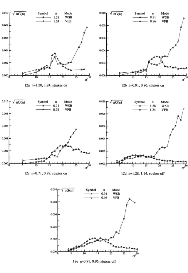
o.0to - q" nG(n) Symbol n Mode 0.010 q" nG(n) Symbol n Mode -- a--- 1.28 WSB • 0.91 WSB -- o--- 1.24 VFB -o--- 0.96 VFB 0.008 0.008 0.006 0.006 0.004 0.004 0.002 0.0[1•2 ' ' ' ' I o.o•o 0.000 ) 5 I0 15 20 25 0[o30 IO 15 20 •03o
12a n--1.28, 1.24, strakes on 12b n=0.91, 0.96, strakes on
0.010 - q" nG(n) Symbol n Mode 0.01 1. •" riG(n) Symbol n Mode _ -- ,•L----• 0.71 WSBL -- a•--- 1.28 WSB -- o--- 0.78 VFB -- o---• 1.24 VFB
/
0.008 0,00 -0,006 0.00 0.1304 0.00 0.002 0.002 0.000 ) • 10 15 20 25 0[030 0"0000 5 10 15 20 25 0[o3012c n=0.71, 0.78, strakes on 12d n=1.28, 1.24, strakes off
o.olo q" nG(n) Symbol n Mode
-- a•-.--- 0.91 WSB + 0.96 VFB 0.008 0.006 0.004 0.002 i i , 0'0000 5 I0 15 20 25 0,030
12e n=0.91, 0.96, strakes off
--n-G(n)
-,F-ThTn
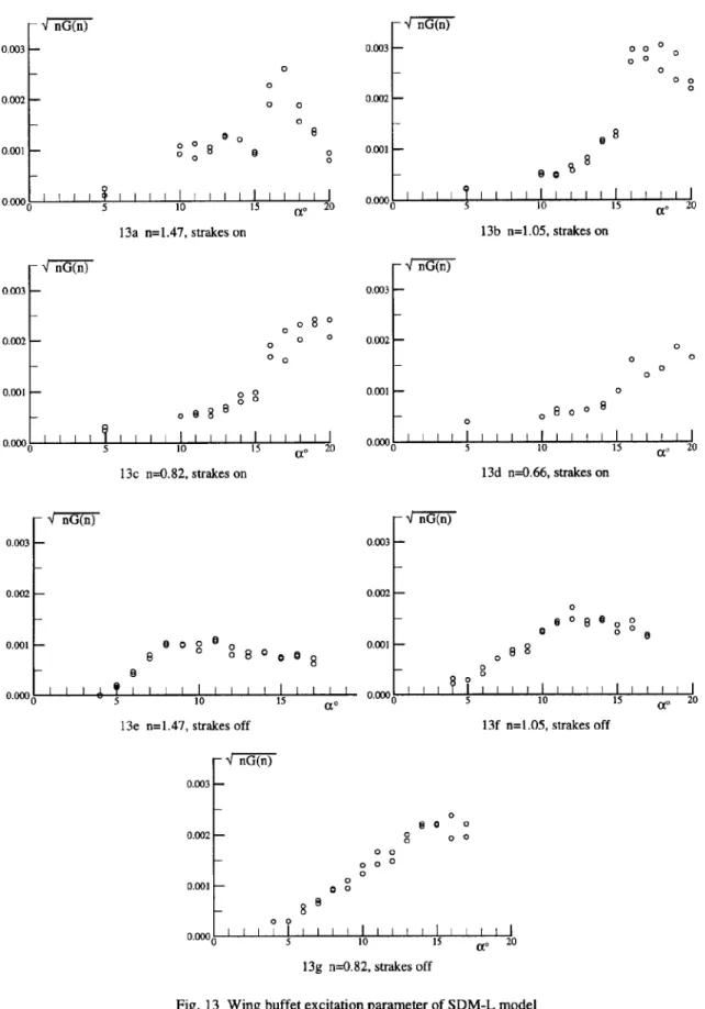
0.003 -0.003 -0 000 00 00 0 0 00 O.D 0.002 0 0.001 0 0 0 0.1 0080 1 1o 0.001 0.00 5 10 13 20 '0 5 10 15 W0 2013a n=1.47, strakes on 13b n=1.05, strakes on
- In-G(n) -/ - -nG(n) 0003 -0.003 0 0 0.002 0 0 0 0.0020 00 0 0 0 0 0 0 0 0.0001 0 0 1.0 0.00 5 10 15 (.20 5 I.DO 10 15 W 20I 13c n=0.82, strakes on 13d n--0.66, strakes on 0.003 -0,003 0.002 -0,002 0 0080 0 0.001 §00 80 00080000 0.0 g8 50 10 S 5 0 0 0I2 0 0 0. 0.002 0 0 00 0 .00 00 0 00 00 0.00 5 10 15 a0 20 13g n--0.82, strakes off
Fig. 13 Wing buffet excitation parameter of SDM-L model at different coditions (WAB mode, 3 --0')
0.004 nG•n) Symbol n Mode A 1.47 WAB o 1.28 WSB 0.003 0.002 A 00 A A A 0 0 0.001 o 0 AA 0 20 A 0 A 0. 0 I 1 1 I , IL . . I I I I I I 0.00(0 5 10 15 (0•20 14a n=1.47 and 1.28 0.004 - nG(n)
i
Symbol n Mode A 1.05 WAB 0 0.91 WSB 0.003 0.002 0 0 0 0 0 A A A A 00 A A 0 0.001 Q 22 ,00 I , I , , I , l I 0 5 10 15 20 14b n=1.05 and 0.91 0.004 -f nG(n) Symbol n Mode A 0.82 WAB 0 0.71 WSB 0.003 0 0 00 0 0.0020 0 AAA 0 A 0.001 05 10 115 210 0 14c n--0.182 and 0.71Fig. 14 Model independence on wing buffet excitation of SDM-L model (strakes off,