Publisher’s version / Version de l'éditeur:
Vous avez des questions? Nous pouvons vous aider. Pour communiquer directement avec un auteur, consultez la première page de la revue dans laquelle son article a été publié afin de trouver ses coordonnées. Si vous n’arrivez pas à les repérer, communiquez avec nous à [email protected].
Questions? Contact the NRC Publications Archive team at
[email protected]. If you wish to email the authors directly, please see the first page of the publication for their contact information.
https://publications-cnrc.canada.ca/fra/droits
L’accès à ce site Web et l’utilisation de son contenu sont assujettis aux conditions présentées dans le site LISEZ CES CONDITIONS ATTENTIVEMENT AVANT D’UTILISER CE SITE WEB.
Internal Report (National Research Council of Canada. Institute for Research in Construction), 1997-06-01
READ THESE TERMS AND CONDITIONS CAREFULLY BEFORE USING THIS WEBSITE.
https://nrc-publications.canada.ca/eng/copyright
NRC Publications Archive Record / Notice des Archives des publications du CNRC :
https://nrc-publications.canada.ca/eng/view/object/?id=18e09bf1-e293-428d-b46b-54f561a3eb9d https://publications-cnrc.canada.ca/fra/voir/objet/?id=18e09bf1-e293-428d-b46b-54f561a3eb9d
Archives des publications du CNRC
For the publisher’s version, please access the DOI link below./ Pour consulter la version de l’éditeur, utilisez le lien DOI ci-dessous.
https://doi.org/10.4224/20338181
Access and use of this website and the material on it are subject to the Terms and Conditions set forth at Proposed Standard Practice for Determination of Volatile Organic Compounds (excluding formaldehyde) Emissions from Wood-Based Panels Using Small Environmental Chambers Under Defined Test Conditions
Zhang, J. S.; Zhu, J. P.; Tsuchiya, Y.; Shaw, C. Y.; Magee, R. J.; Lusztyk, E.; Kanabus-Kaminska, J. M.
,, 1
National Research Conseil national Council Canada de recherches Canada
-
m n . 7 lnslitute for lnstitut deResearch in recherche en Construction const~ction
A
Proposed Standard Practice for Determination of
Volatile Organic Compounds (excluding formaldehyde)
Emissions from Wood-based Panels Using Small
Environmental Chambers Under Defined Test Conditions
by J.S. Zhang, J.P. Zhu, Y. Tsuchiya, C.Y. Shaw, R.J. Magee, E. Lusztyk and M. Kanabus-Kaminska
I R C Ser
Received an: 06-52-97 I n t e r n a l r e p o r t
Internal Report No. (IRC-IR-746)
Date of issue: June 1997
n a l r e p o r t ( I n s t i t u t e f N A L Y S E
This internal report, while not intended for general distribution, may be cited or referenced in other publications.
A Prouosed Standard Practice for Determination of Volatile Organic Compounds (excluding formaldehyde) Emissions from Wood-based paneis
Using
smallEnvironmental Chambers Under Defined Test Conditions
J.S.
Zhang, J.P. Zhu, Y. Tsuchiya, C.Y. Shaw,R.J. Magee, E. Lusztyk and M. Kanabus-Kaminska
Address: M-24, IRC, NRC, Montreal Road, Ottawa, Ontario K I A OR6 Canada Phone: 613-993-9538, Fax: 613-954-3733, E-mail: [email protected]
1. Scope
1.1 The practice measures the volatile organic compounds (VOCs), excluding formaldehyde, emitted from manufactured wood-based panels. An pre-screening analysis is used to identify the VOCs released by a wood-based panel product. Emission factors (i.e., emission rates per unit surface area) for the VOCs of interest are then determined by
measuring the concentrations in a small environmental test chamber containing a specimen and being ventilated at a constant air change rate under the standard environmental
condition. For formaldehyde determination see ASTM E1333-90.
1.2 The VOC concentrations in the environmental test chamber are determined by adsorption on an appropriate single or multi-sorbent tube (for example, a sorbent tube containing three sorption materials: glass beads, Tenax TA and Ambersorb), followed by thermal desorption and combined gas chromatography/mass spectromeq (GCIMS) or gas chromatographylflame ionization detection (GCIMS). The air sampling and analytical method recommended in this practice is generally valid for the identification and quantification of VOCs with boiling points between 30 "C and 260 OC.
Note I . The dejinition of VOC is somewhat subjective. The user shall realize that the compounds being captured by a sorbent tube depend on the adsorbents and sampling volume selected. The user shall have a thorough understanding of the limitations of each adsorbent used.
1.3 The practice is primarily used for testing newly manufactured individual wood- based panels (such as particleboards, plywood, oriented strand board, etc.) for the purpose of comparing the emission characteristics of different products under the standard test condition. The origin and history of the test panels shall be documented in detail if they are collected using a different procedure as that specified in this practice. The data could he used to assist the analysis of the impact of wood-based panels on the VOC concentrations in buildings by using an appropriate indoor air quality model, which, however, is beyond the scope of this practice.
IRCINRC CMEIAQ: Report 1.2 (06197)
1.4 Values stated in SI units are to be regarded as the standard.
1.5 This practice does not purport to address all of the safety associated
with its use. It is the responsibility of the user of the standard to establish appropriate safety and health practices and determine the applicability of regulatory limitations prior to use. For specified hazard statements see Section 7.
2. Reference Documents
2.1 ASTM Standards
Dl356 Definitions of Terms Related to Atmospheric Sampling and Analysis Dl605 Practices for Sampling Atmospheres for Analysis of Gases and Vapor Dl914 Recommended Practice for Conversion Units and Factors Related to Atmospheric Analysis
D3 195 Recommended Practice for Rotameter Calibration
D3609 Recommended Practice for Calibration Techniques Using Permeation Tubes D3686 Practice for Sampling Atmospheres to Collect Organic Compound Vapor (Activated Charcoal Tube Adsorption Method)
D3687 Practice for Analysis of Organic Compound Vapor Collected by the Activated Charcoal Tube Adsorption Method
D5116-90 Standard Guide for Small Scale Environmental Chamber Determinations of Organic Emissions from Indoor Materials/Products
E355 Recommended Practice for Gas Chromatography Terms and Relationships E380-93 SI Standard
E741-83 Standard Test Method for Determining Air Leakage Rate by Tracer Dilution.
E1333-90 Standard Test Method for Determining Formaldehyde Levels from Wood Products Under Defined Test Conditions Using a Large Chamber
2.2 Other Documents
ACGIH Threshold Limit Values (TLV(B)) for Chemical Substances and Physical Agents in the Work Environment and Biological Exposure Indices
ASHRAE 62-89 Ventilation for Acceptable Indoor Air Quality
3. Terminology
3.1 Definitions - For definitions and terms commonly used in ASTM standards
including this standard, refer to ASTM Dl356 Definitions. For an explanation of units, symbols, and conversion factors, refer to ASTM Practice D1914.
3.2.1 Air change rate ( I k ) - The flow rate of clean air (defined in 3.2.3) in m3/h supplied into the chamber divided by the net air volume of the environmkntal test chamber (i.e., volume of an empty chamber minus the volume taken by all contents in the chamber during testing such as the test specimen holder, test specimen, sampling port, etc.) in m3.
2 3
3.2.2 Chamber loading ratio (m im ) - the total exposed surface area of each test specimen divided by the net air volume of the environmental test chamber.
3.2.3 Clean air
-
air that satisfying each of the following criteria: TVOC (as defined in 3.15) concentration I 10 fig/m3, concentration of any individual compound 5 0.5 fig/m3,particulate concentration I 100 particles/mbf 0.5 fim diameter or larger, and
ozone concentration 1 2 0 fig/m3.
The clean air can be trace pure air supplied from compressed air cylinders which meets the requirement listed in 3.2.3, or ambient air which is conditioned by removing organic compounds and particles through charcoal filtration/catalytic oxidization, and HEAPA filter, respectively, or by other equivalent means to meet the requirements listed in 3.2.3.
3.2.4 Elapsed time - time measured from the time zero as defined in this practice.
3.2.5 Emission factor - the mass of a VOC or TVOC emitted per unit time and per
unit area of the exposed surface of the test specimen, figl(h m2).
3.2.6 Emission rate - the mass of a VOC or TVOC emitted from the test specimen
per unit time, ~ g l h .
3.2.7 Environmental test chamber (ETC) - a chamber in which a material can be
placed and tested to determine the VOC emission rate under the standard test condition. 3.2.8 Environmental enclosure
-
a chamber or other enclosure in which the environmental test chamber@) is placed. It shall have the capability of maintaining the temperature and relative humidity at the standard temperature (23M.5 OC) and relativehumidity (50%+5%
RH)
conditions during the period of loading the test specimen, andmaintain the standard temperature condition (23M.5 OC) during the measurement period
(the standard humidity conditions is maintained by the air supplied to the chamber in the measurement period).
3.2.9 G C M S - gas chromatography equipped with a mass spectrometer. The GC
shall be equipped with a cryogenic unit if measurements of VOCs with low boiling points
IRCNRC CMEIAQ: Report 1.2 (06197)
3.2.10 GCFID - gas chromatography equipped with a flame ionization detector. The
GC shall be equipped with a cryogenic unit if measurements of VOCs with low boiling points (<50 OC) are required.
3.2.11 Pre-screening analysis - a procedure for identifying the VOCs emitted from a test specimen. The results are used to determine the appropriate GCIMS or GCFID
analytical method for the separation and quantification of VOCs of interest, and air sampling volume for subsequent dynamic chamber tests.
3.2.12 Internal standard - a VOC that is not emitted by the test specimen, which can be injected at a known rate into the exhaust of the environmental test chamber to verify sample collection and analytical procedures.
3.2.13 Nominal time constant - the time required to obtain 1 air change in the environmental test chamber, which is equal to the inverse of the air change rate.
3.2.14 Standard environmental condition
-
the conditions of air at 23 "C, 50% RH and 101.33 kPa in pressure. The concentration data shall be converted to the equivalent concentration under this standard environmental condition.3.2.15 Standard test condition -defined in this practice as the environmental conditions maintained in the environmental test chamber during the test period, i.e., 23k0.5
0
C in temperature, 50%k5% RH in relative humidity, 1k0.03 ACH in supply airflow rate and 0.40rt0.01 m2/m' in chamber loading ratio.
Note 2. The rates of VOC e~nissiorzs from wood-basedpanel products are generally controlled by VOC diffusions within the material. The airJlow condition (air velocity urzd turbulence) over the test speci~nerz has insignificant effect on the emission rates, and is therefore, not specified in the standard test condition.
3.2.16 Time Zero - defined as the time when the environmental test chamber is closed and supply airflow started after loading the specimen into the chamber.
3.2.17 Tracer gas
-
a gaseous compound not emitted by the wood-based panel, nordoes it exist in the supply air to the chamber, and can be used to determine the mixing characteristics of the environmental test chamber and provide a cross-check of the air change rate measurements.
3.2.18 TVOC-by-GCIEID @g) - the sum of the mass of all individual VOCs which
are measured by sampling with a sorbent tube, quantified by a thermal desorber-GCFID system, and reported as the toluene equivalent. It is calculated by the following procedure: (1) convert the area count of each peak to the equivalent toluene mass by using the
calibration curve for toluene; and (2) sum all the equivalent toluene mass, the result of which is the TVOC-by-GCFID mass.
3.2.19 TVOC-by-GUMS (pg)
-
the sum of the mass of all individual VOCs which are measured by sampling with a sorbent tube, quantified by a thermal desorber-GC/MS system, and reported as the toluene equivalent. It is calculated by the foilowing procedure: (1) convert the area count of each peak to the equivalent toluene mass by using thecalibration curve for toluene; and (2) sum all the equivalent toluene mass, the result of which is the TVOC-by-GCiMS mass.
3.2.20 Volatile organic compound (VOC) - an organic chemical compound with a
boiling point between 30 OC and 260 "C. (see Note 1)
3.2.21 Wood-based panel test specimen
-
a specimen of panel cut from an original wood-based panel sample such as particleboard, oriented strand board (OSB), and plywood.4.
Significance and Use4.1 The effects of VOC sources on the indoor air quality in buildings have not been well established. However. a wide variety of concerns have been raised. One basic
requirement that has emerged from indoor air quality studies is the need for well characterized test data on the emission rates of VOCs from building materials. These - emission rate data will allow building designers to compare the emission characteristics of products under the same conditions.
4.2 This practice describes a procedure of using
a
small environmental test chamber to evaluate the emission factors (i.e., emission rates per unit surface area) of VOCs from wood-based panels over a specified period of time. A pre-screening analysis procedure is also provided to identify the VOCs emitted from the products, determine the appropriate GC/MS or GCFID analytical procedure and air sampling volume for the subsequentenvironmental chamber testing. Conditions specified for the environmental chamber testing procedure include:
4.2.1 Collection and transportation of material samples. 4.2.2 Storage and preparation of test specimen prior.
4.2.3 Chamber loading ratio
-
the ratio between the exposed surface area of the test specimen and the net volume of the environmental test chamber.4.2.4 Temperature and relative humidity in the environmental test chamber. 4.2.5 Number of air changes per hour supplied to the chamber.
4.2.6 Air mixing conditions within the environmental test chamber. 4.2.7 Background concentration in the environmental test chamber.
IRCNRC CMEIAQ: Report 1.2 (06197)
4.2.8 Cleaning and conditioning of sorbent tubes for air sampling.
4.2.9 Specified time intervals at which air is sampled from the environmental test chamber.
4.2.10 Methods for determining the concentrations of VOCs in the air sample. 4.2.11 Method for calculating the emission factor.
4.3 Test results obtained with this practice provide a basis for comparing the short term (within a month) VOC emission rates of different wood-based panel products. They can be used to assist manufacturers' effort of reducing VOC emissions from their products. They can also be used to select building materials for reducing VOC concentrations in buildings.
4.4 The concentrations measured in the chamber shall not be considered as the
resulted concentrations in the actual indoor environment.
5. Apparatus
5.1 This practice requires the use of an environmental chamber testing system, an air sampling system and a chemical analysis system. ASTM D5 116-90 on "Standard Guide for Small-Scale Environmental Chamber Determinations of Organic Emissions From Indoor MaterialsProducts" provides a general guide for conducting small environmental chamber tests. The following sections describe the requirements that are specific to this practice:
5.2 The E~zvironmental Chamber Testing Systenz
-
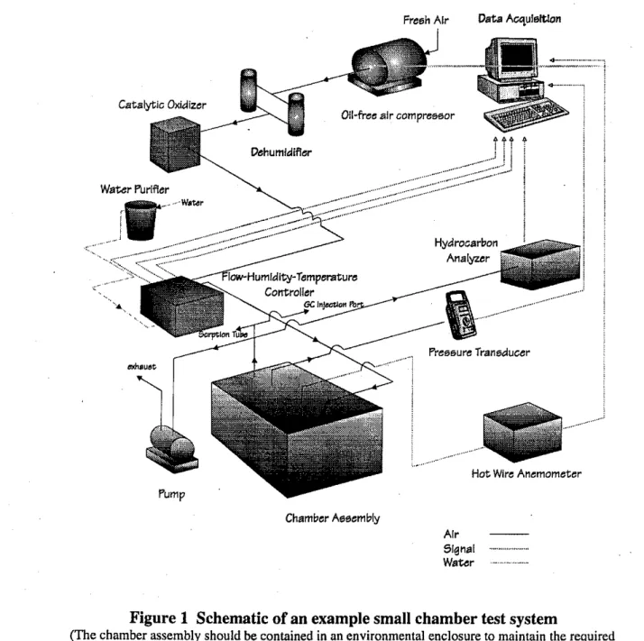
a small environmental chambertesting system shall include an environmental test chamber, an environmental enclosure, equipment for supplying clean and conditioned air to the chamber, and outlet fitting for sampling the air exhausted from the chamber. Figure 1 illustrates an example of such systems. All materials and components in contact with the panel specimen or air stream from the chamber inlet to sample collection point shall be chemically inert and accessible for cleaning. Suitable materials include stainless steel and glass. All gaskets and flexible components shall be made from Teflon or other chemically inert materials.
5.2.1 The Environmental Test Chamber -The standard chamber for this practice shall have a volume of 0.05 m3 with the interior dimensions of 0.5 mm by 0.4 m by 0.25 m high. A chamber with a different size and shape may also be used if the same standard test condition (see section 3.2.15) can be maintained. The supply air system is recommended to have an inlet port with distributed openings to assist mixing between the supply air and chamber air. It is also desirable to have an outlet port with distributed exhaust openings to ensure that concentration measured at the chamber exhaust is the average concentration in the chamber. The chamber design shall meet the following criteria:
5.2.1.1 Air-tightness of the chamber: The nominal air leakage rate of the chamber shall be less than 1% of the air change rate used for the emission test (i.e:, 4.01
ACH
for the standard test condition) at 10 Pa. This is evaluated by the following procedure: (1) seal the outlet of the chamber; (2) supply air to the chamber through the inlet and adjust the airflow rate so that the pressure difference between the inside and outside of the chamber is maintained at 10k5 Pa, which is measured by a micro-manometer. The airflow raterequired to maintain the pressure difference is the nominal leakage rate of the chamber. 5.2.1.2 Air mixing in the chamber: Good air mixing in the chamber s h d be
achieved to ensure that concentrations measured at the chamber exhaust is representative of those in the chamber. This may be determined by using the following tracer gas decay method: (1) place a small mixing fan (e.g., the cooling fan for a personal computer) in the chamber; (2) with the small environmental chamber operating under the standard test condition, and the mixing fan operating, inject a small amount (a pulse) of an inert tracer gas (e.g., SF6) into the chamber directly or via the supply air; (3) allow 5 minutes for the gas to mix with the chamber air and then turn off the mixing fan. The time when the mixing fan is turned off is defined as t=0; (4) measure the concentrations of the tracer gas at the exhaust of the chamber at the following time points: t=O, 0.25 t,,, 0.5 t,,, 1.0 t,,, 1.5 t,, and 2.0 t,, where t, is the nominal time constant and is equal to 1.0 h for the standard test condition. The measured concentrations are compared to the values given by the following theoretical equation under the perfect mixing condition (in which the concentrations measured at the exhaust is the same as that in the chamber):
where,
co
= initial concentration at t=O, pglm3;C(t) = concentration at time t, j@m3;
N
= air change rate, llh;t = time from the s t a t of the air purging, h
The maximum difference between the measured and calculated theoretical values shall be within +5% of the theoretical value. The above mixing test shall be conducted with a simulated test specimen placed in the chamber.
Note 3. The above method is a simplified version of the decay method described in
ASTM
DI16-97. Alternatively, the step-up method described in
ASTM
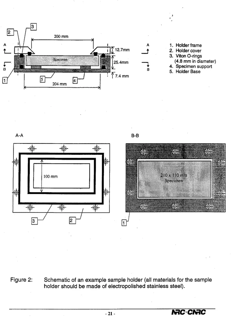
0116-97 may also be used to check the mixing condition in the chamber.5.2.1.3 A stainless steel tray shall be used to hold the test specimen so that only the test surface of the specimen is exposed to the air. The tray shall also be designed to
minimize the emissions from edges of the specimen. A design example is shown in Figure 2.
IRCh'RC CMEIAQ: Report 1.2 (W)
5.2.1.4 The chamber plus the stainless tray shall have minimum sink effect - The recovery factor determined by the following procedure shall be higher tlian 95% for decane: (1) seal the supply inlet and exhaust of the chamber; (2) Inject 5 p g of vaporized decane into the chamber; (3) Take an air sample from the chamber at 5 minutes after the injection, and refer to this concentration as the initial concentration
Cb
at t = 0; (4) At t=O, begin purging the air through the chamber at the standard test condition (i.e., 23 O C , 50% RH and1 ACH); (4) Take air samples fiom the chamber exhaust at the following times after the start of purging: t l = 0.25 t,, 12=0.5 t,, , t3 = 1.0 t,, t4 = 1.5 t,, t5 = 2.0 t,, t 6 = 3.0 t,, t7 = 4.5 t,, t8 = 6 t,, t9 = 8 t,, and t10 = 10 t,, where t, is the nominal time constant and is equal to 1.0 h for the standard test condition; (5) Calculate the recovery factor (RF) as follows:
where,
RF = recovery factor, %;
N = air change rate, llh;
CO = initial concentsation at t=O, pg/m3;
C(t,) = concentration at time ti, pg/m3 (i=O, 1, 2,
...,
10);t
,
= time from the start of the air purging, h.The above sink effect test shall be conducted after the mixing condition in the chamber has been verified (see section 5.2.1.2).
Note 4. The concentration decay is usually close to the3rst-order expo~zential decay curve (i.e., C(t)/C,, = e-N/'). The above sampling time intervals are chosen such that the amount of concentration decrease during each sampling interval will be similar.
Note 5. The above sink effect test is to check
if
the chamber system has significant izorl- reversable sinks. Non-revirsoble sink effect would result in under estimation of theernissiolz rates in the ei~irorvnental chamber tests (see section 8.2). The chamber may also have irreversible sink effect (i.e., compounds adsorbed at one time may re-emit in a later time), but such effect on the results of the environmental chamber tests is expected to he minimal due to the procedure adopted for the environmental chamber tests (i.e., the
chamber is ventilated continwusly during the test, see section 8.2) as well as the rizaterial.~ used in the chamber construction.
5.2.1.5 The environmental test chamber shall be contained in an environmental enclosure (see 5.2.2).
5.2.2 Environmental enclosure - This enclosure shall be of sufficient size to accommodate the test chamber, and shall be capable of maintaining the temperature at 23.0k0.5 'C and relative humidity at 50%k5% RH during the period of loading the test specimen, and maintain the temperature at 23.W0.5 'C in the chamber during the entire testing period. Once the door of the chamber is closed, the humidity condition in the chamber is maintained by the air supplied to the chamber.
5.2.3 Clean Air Supply System- This system shall be capable of supplying a controlled flow of clean air into the test chamber. The concentration measured at the chamber inlet shall meet the condition specified in section 3.2.4 at the airflow rate equal or larger than 1 ACH. A typical clean air supply system shall include the following equipment (Figure 1):
5.2.3.1 An air pump(s) or an oil-free compressor capable of supplying the air at a rate of 1.0 air change per hour, based on the net volume of the environmental test chamber. A particulate filter shall he installed for the air intake.
5.2.3.2 A dehumidifier (e.g., a desiccant drier) capable of keeping the relative
humidity below 45% RH.
5.2.3.3 A catalytic oxidizer or equivalent air purifier (e.g., activated carbon filter) - capable of removing organic compounds so that the concentrations of TVOC and any individual VOCs are below 10 fig/m3 and 0.5 pg/m', respectively.
5.2.3.4 An air conditioning device and an airflow controller capable of controlling the airflow rate, temperature and relative humidity of the supply air at 1.OL0.03 ACH, 23.0k0.5 OC and 50*5%
RH,
respectively. Deionized water (or equivalent) shall be used in the humidification.5.2.3.5 An exhaust air pump and an airflow controller to control the pressure in the chamber. The airflow controller shall be adjusted so that the air pressure in the chamber will be positive relative to air pressure outside the chamber despite of the fluctuations in the ambient air pressure. A typical pressure to be maintained in the chamber is 1&5 Pa relative to the outside of the chamber.
5.2.3.6 Sensors and a recording system for monitoring the air flow rate, temperature, relative humidity, and pressure in the environmental test chamber.
5.2.4 The background concentration of the environmental test chamber measured at the exhaust of the chamber by a sorbent tube shall meet the following criteria:
5.2.4.1 The background concentration of TVOC-by-GCIMS or TVOC-by-GCFID shall not exceed 20 p g / m b r 116 of the lowest TVOC concentration to be measured, whichever is lower.
5.2.4.2 The background concentrations of target individual VOCs shall not exceed 116 of the lowest concentrations of corresponding individual VOCs to be measured. Note 5. Conventionally, the lnilzirnum quantifiable concentration is determined by:
C,,,,,, = c
+
10 sIRCNRC CMEIAQ: Report 1.2 (06197)
where, C,,,i,, is the minimum quantifiable concentration; c is the mean background
concentration; s is the standard deviation of the background concentration during the test period. For simplicity, it may be assumed that s = 0.5 c. As a result,
C,,",,
= 6 c.Note 6. The 20 pg/m3 limit set for
TVOC
in 5.2.4.1 is the minimum level of cleanness that the test chamber system shall have.5.3 Air Sampling System -The airsampling system shall include a sorbent tube, an air sampling pump and a airflow controller which can measure and control the air flow rate through the sampling system to within*% of a specified value. All system components between the chamber and the sorbent tube shall be constructed of chemically inert materials.
5.3.1 The sorbent tube shall be connected directly to the chamber exhaust by using a short ( ~ 0 . 1 5 m) stainless or Teflon tubelconnector. The pump shall be operated in suction mode downstream of the sorbent to avoid contamination of air samples by the pump.
5.3.2 For collection of VOCs in the exhaust air of the test chamber, an appropriate single or multi-layered sorbent tube shall be used depending on the VOCs to be measured. For example, a 3-layered (glass beads, Tenax TA', Ambersorb xE-340') tube can be used to measure VOCs typically emitted from particleboards.
5.3.3 Sampling of the exhaust air shall not affect the airflow rate control of the test chamber. The airflow controller for the exhaust air pump shall be adjusted before air sampling so that the air pressure in the chamber will remain positive during the air sampling period. A sampling flow rate of less than 113 of the total supply airflow rate to the test chamber is recommended to avoid excessive depressurization in the chamber during the sampling period. Recommendations of the sorbent tube manufacturerlsupplier shall be followed in selecting the sampling airflow rate and sampling period to avoid breakthrough of VOCs through the sorbent tube. The air sampling volume (i.e., sampling flow rate times the sampling perlod) will depend on the breakthrough volume of the least retained
compounds, concentrations to be measured, and detection limits of the analytical method. The lowest concentration to be measured quantitatively shall be higher than 3 times of the detection limit of the analytical method. For example, if the detection limit of a GUMS analytical system is 0.001 pg per tube sample for a VOC of interest, and the lowest
concentration to be measured is 1.0 pg/m3, a minimum of 0.003 m' or 3 L (i.e., 0.001 x 3 1 1.0) air sample shall be used. A proper sampling volume shall be determined through a pre- screening analysis (section 8.1).
5.4 Chenzical A~talysis System -The chemical analysis system is a thermal desorber
connected to a G U M S system or a GCIFID system.
5.4.1 Thermal Desorber - A single or multi-tube thermal desorber. Desorption conditions shall be chosen such that desorption from a sample tube is complete. The desorption efficiency shall be over 90% for VOCs of interest.
5.4.2 GCiMS System
-
A G C N S system can be used for both identification of VOCs in the pre-screening analysis and quantification of the VOCs in the environmental chamber testing.5.4.2.1 For identification of VOCs, the GCMS is operated in the scan mode, and shall be capable of scanning mass range from 20 to 350 amu (atomic mass unit). The measured spectrum shall be compared to those in a standard mass spectrum library such as NBS75K to identify the individual VOCs detected. Selected VOCs of interest shall be confirmed by spiking with the corresponding standards (see section 8.1).
5.4.2.2 For quantification of individual VOCs of interest, the G C N S system shall be operated under selected ion monitoring mode. At least three ions shall be monitored for each VOC of interest. Other conditions used in section 5.4.2.1 shall be maintained.
5.4.3 GCIFID System - A GC/FID system can be used for quantification of VOCs of
interest as an alternative to GCIMS. The identification of the VOCs of interest in a GCFI' chromatogram shall be confirmed by a GCIMS analysis or by spiking with the
corresponding standards (see section 8.1).
5.4.4 Optimal operating conditions (GC column and temperature program) shall be selected for GCiMS and GCIFID system based on the pre-screening analysis (section 8.1).
5.4.5 Calibration - Initial calibration of the analytical system shall be conducted before testing each type of material products. Initial calibration is conducted by analyzing standards of selected VOCs (or toluene for TVOC, see 5.4.5.2) at different concentrations. At least five different concentrations covering anticipated VOC concentration range in the test are needed for such calibration. User of this practice shall demonstrate that the analytical system has a linear response in the anticipated VOC concentration range.
5.4.5.1 If GCFID system is used for the quantification, single point calibration checking shall be conducted on each day the system is used. If the result of such single point checking deviates less than +lo% from the initial calibration line, the initial
calibration line shall be used to calculate the mass concentrations. Otherwise, problem shall be identified and the system fully re-calibrated as in the initial calibration (section 5.4.5).
5.4.5.2 If GCIMS system is used for the quantification, daily calibration shall be conducted at the lowest and highest concentration levels (i.e., a two point calibration) as a minimum. Results of this daily calibration shall be used to calculate the concentrations they deviate less than 10% from the previous day and 25% from the initial calibration.
Otherwise, problem shall be identified and the system fully re-calibrated as in the initial calibration (section 5.4.5).
IRCA'RC CMEIAQ: Report 1.2 (06497)
Note 7. D~rerent calibration practices are specified for GC/FID (section 5.4.5.1) and
GC/MS (section 5.4.5.2) system because a GUMS system is usually subject to more day to day variations than a G C M D system in terms of the quantification.
5.4.5.3 If the testing objective is to measure the emission factors of target individual compounds, the thermal desorber-GCIMS or thermal desorber-GCFID system shall be calibrated for each individual compound with the standards of the same compound.
5.4.5.4 If the testing objective is to measure the TVOC concentration, the thermal - - desorber-GCFID system or thermal desorber-GCMS system shall be calibrated by using toluene as the reference standard. The result shall be reported as the concentration of
toluene equivalent TVOC-by-GC/FID or TVOC-~~-GCIMS, depending on which system is
used. In this case, GC/MS shall be operated in full scan mode (20 to 350 AMU) and peak areas of the total ion currency must be used.
5.5 The sampling and analysis procedure and equipment shall have a detection limit that is less than 113 of the lowest concentration to be measured (See 5.3.3).
6. Hazards
6.1 The transportation, handling, cutting, testing and clean-up of wood-based panel involve a number of chemical and physical hazards.
6.2 Proper workplace health and safety procedures and good laboratory practice shall be developed and implemented.
6.3 Cleaning chemicals - Appropriate procedures shall be developed and
implemented for using disposing such chemicals.
7. Material Sampling, Storage, Preparation of a Test Specimen and its Placement in
the Environmental Test Chamber
7.1 Material Collection, Packaging, and Transportation
7.1.1 The testing laboratory shall secure the material sample in an unbiased manner. Material samples shall be collected at the manufacturer by a qualified person and delivered to the testing laboratory directly by using the following procedure:
7.1.1.1 Select one panel from the center of a freshly (within a week) manufactured stack.
7.1.1.2 Cut 300x300 mm (1 ft
x
1 ft) sample(s) from inside the perimeter of the panel, minimum 300 mm (I ft) from the sides and ends.7.1.1.3 Wrap each sample separately in pum aluminum foil (no tape, shiny side out), and place them in a Tedlar bag or equivalent The bag and aluminum foil shall be provided by the testing laboratory. The background toluene equivalent TVOC-~~-GC/FID concentration of the air in an empty bag shall be less than 50 k g / m h d concentration of any single component shall be less than 5 pg!m3. This shall be checked by filling the bags with clean air and taking an air sample at 24 hour after filling the bag with the clean air. The aluminum foil shall be kept clean in a separate Tedlar bag when shipped to the manufacture for collecting material samples.
7.1.1.4 Send the samples to the testing laboratory within 48 hours by overnight parcel service.
7.2 Sample Storage - Material samples shall be stored in a conditioned room at a temperature of 23.e1.0 OC after receiving. The minimum storage time shall be forty eight (48) hours to allow equalization of the sample temperature with the ambient air. The material samples shall be tested within two weeks after being received.
7.3 Preparation of Test Specimens
7.3.1 Specimen size - The standard size of the specimen shall be 210x1 10 rnrn including 5 mrn on each side to be sealed by the specimen tray. A clean saw shall be used to cut the samples into the specimen size.
The
saw shall be cleaned by scrubbing with methanol and rinsing with deionized water.7.3.2 Sealing of edges and the non-testing surface - All of the four edges and the non-testing surface shall be well sealed. A specially designed specimen tray (see section 5.3.1.3) or an equivalent sealing method shall be used. The exposed testing surface area shall be 0.02 m2 (200x100 mm).
7.3.3 The time interval for preparing the specimen (i.e., from opening the sample bag to placing the specimen in the chamber) shall be between 20 and 30 minutes.
7.4 Placement of the Test Specimen in the Environmental Test Chamber
7.4.1 The specimen shall be placed at the center of the chamber bottom so that air circulation in the chamber is not affected by the specimen.
8. Test Procedure
8.1 Pre-Screening Analysis Procedure
8.1.1 A pre-screening analysis shall be conducted to identify VOCs emitted by the product, set proper operating conditions for the GCJMS and/or GCJFID system, select target VOCs, and determine a proper air sampling volume for subsequent environmental chamber
IRCNRC CMEIAQ: Report 1.2 (OM97)
tests. The environmental chamber can be used with the following procedure for this purpose:
8.1.1.1 Follow the environmental chamber testing procedure in 8.2.1 through 8.2.6.2 to prepare the chamber air and sorbent tubes for sampling.
8.1.1.2 Take multiple air samples using sorbent tubes with different air sampling volumes ranging from low to high (e.g., 1 L, 3 L and 5 L). This shall be done after the environmental test chamber has been supplied with clean air for 6 air changes at the
standard air flow rate (i.e., 6 hours under the standard test condition). This is to ensure that approximately 99.75% of the background contaminants introduced during the sample loading period be removed. If the concentration in the chamber is too low for identification by a G C M S system operating in the full scan mode, the supply airflow rate may be shut off for a certain period of time (e.g., 24 hours) to allow concentration in the chamber to build UP.
8.1.1.3 Analyze the sorbent tubes by using the G C M S (preferably in the order of low to high volume samples to avoid possible over loading of the analytical system). Different GC operating parameters (columns and temperature program) may be tested to obtain a good separation of emitted VOCs. The results will be used to determine a proper set of GC operating parameters for subsequent environmental chamber testing. More sorbent tube samples may be taken from the environmental test chamber if necessary. 8.1.2 VOCs emitted by the product shall be identified based on the results of G C M S analysis (see section 5.4.2). The selection of major VOCs for subsequent environmental chamber testing depends on the objective of the testing. For each selected VOC, identification shall be confirmed by spiking with a corresponding VOC standard.
8.1.3 A proper air sampling volume shall be determined for the subsequent
environmental chamber testing so that the amount of VOC mass measured is at least 3 times higher than the detection limit of the GCIMS and/or GClFlD system(s) (section 5.3.3).
8.2 Enviroizmental Chamber Testing Procedure
8.2.1 Cleaning
-
Prior to testing, the environmental test chamber, together with all internal hardware and equipment shall be cleaned by scrubbing the interior surfaces with an alkaline detergent, followed by a thorough rinsing with tap water, scrubbing with methanol and then rinsing with deionized water. The chamber and equipment shall be dried, and placed in the temperature enclosure.8.2.2 Purging - The environmental test chamber shall be operated at the standard
environn~ental test condition (i.e., 23 'C, 50% RH and 1 ACH) for a minimum of 6 hours so
that at least 99.75% of the background contamination introduced when the door of the chamber will be removed.
8.2.3 Checking of Background Concentration - An air sample shall be taken at the exhaust of the chamber by using the sorbent tube to check the backgrourid concentration. The background VOC concentrations shall meet the criteria specified insections 5.2.4.1 and 5.2.4.2. Otherwise, the testing system shall be checked for the cause of the excessive background contamination and steps taken to eliminate this contamination. The
background concentration is denoted as Cbr, and will be used in the calculations in section 9.1.1.
8.2.4 Preparation of the test specimen (see section 8.3).
8.2.5 Loading of Test Specimen
-
Open the chamber, position the specimen systemat the center of the chamber bottom, and close the chamber. Record the time when the chamber door is closed, which is defined as the zero time for the environmental chamber testing.
8.2.6 Sampling
8.2.6.1 Clean and condition the sorbent tubes within 72 hours before air sampling. 8.2.6.2 Purge the sampling porttline for 5 minutes prior to the collection of air samples.
8.2.6.3 Take air samples at the 24 hand 72 h from the zero time (section 8.2.5) to determine the concentrations of TVOC and interested compounds at these two time points. Sampled tubes shall be capped, sealed and kept in a clean environment till time for analysis. The tubes shall be analyzed within 7 days after the sampling time.
Note 8. More air samples may be taken between 24 h and 72 h, and after 72 h if more detailed characterization of the VOC emissions is of interest, depending on the objectives of the testing.
8.2.6.4 Unloading and background verification
-
Remove the specimen after the air sample has been taken at 72 h. Take an air sample from the air supply tubellineimmediately upstream of the chamber to verify the background concentration of the supply air. It the concentration of the selected VOCs exceed the background levels measured before loading the specimen, the problem shall be identified and corrected, and the test shall be repeated.
9. Data Analysis and Interpretation
9.1 The emissions of VOCs from wood-based panels are generally characterized by slowly decaying emission rates. For the purpose of this practice, the emission factor (i.e., the emission rate per unit of exposed surface area of the test specimen) is assumed to follow a first order exponential decay:
IRCINRC CMEIAQ: Report 1.2 (06197)
where,
EF(t) = emission factor at time t, pg/m2h;
EFo = initial emission factor at time zero, ~ ~ l m ~ h ;
k = exponential decay constant, lih.
Note 9. The first order exponential decay model is used in this practice for its simplicity
and adequacy to represent the emission test data from 24 h to at least approximately one
month. Caution shall be exercised when it is used to predict emission rates for a longer term (i.e., after a month).
For an individual VOC of interest or TVOC, EFo and k can be calculated by the following simplified procedure (Zhang et al. 1997):
9.1.1 Determine the concentrations for the air samples taken at the elapsed times of t l = 24 h and t2 = 72 h, and denote them as C1 and C2, respectively.
9.1.2 Calculate the corrected concentrations as:
where,
C l c = corrected concentration in the chamber measured at t l = 24 h;
C2c
=
corrected concentration in the chamber measured at t2 =72 h;9.1.3 Calculate the first approximations of emission factors at t l and t2 by the following equations:
efl = C l c
NIL
ef2 = C2c
NIL
where,
efl = first approximation of the emission factor at tl = 24 h; ef2 = first approximation of the emission factor at t2 = 72 h;
L
= ETC loading ratio, exposed surface area divided by the volume of thechamber; m'/m3;
N = air change rate, llh;
9.1.4 Calculate k and EFO by using the following equation: k = [ln(efl/ef2)] / At
EFO = (I-k/N) efl I [(efl1ef2)-'"'~')] where,
9.2 The above simplified calculation procedure is valid in general assuming that the measurement of the concentrations Clc and C2c are accurate and
EF
=E&
ea is valid. However, current air sampling and chemical analysis techniques can only provide a precision of about +lo% (relative standard deviation). As a result, sources with lk1<5.0x
shall be regarded as constant emitters. In this case, the testing results shall be reported as follows:
Note 11. An alternative is to conduct the test for a longer period of time so that decay constant that is less than 5.0 x 10.' can also be measured.
Note 12. With the two corrected concentration C l c and CZc, the initial emission factor (EFO) and the decay constant (k) can in fact be computed by an iteration procedure with no approximation required (i.e., the exact solution can be found). The simplified procedure described above is adopted in this practice because it is simpler to use and provides
sufficient accuracy. If more air samples are taken, regression analysis can ako be used to determine EFO and k. Users shall refer to ASTM D5116-90 for the detailed calculatiorz procedure.
9.3 The emission factors determined using the above procedure describe the emission characteristics of the specimen under the standard test condition. These data can be used directly to compare the performance of different products, and for estimating the emission rates up to a month period after the production. They shall not be used to predict the emission rates over longer period of time (i.e., more than a month) or under different environmental conditions.
10. Report
10.1 The report shall include the following information:
10.1.1 Testing objectives - the purpose of the testing project and intended use of the results shall be stated.
10.1.2 Testing laboratory identification - the name, address, phonelfax numbers and contact person.
10.1.3 Product identification
-
the name, specific identifiers from the manufacturer and a brief description of the product, its application, and history shall be provided.IRC/NRC CMEIAQ: Report 1.2 (06197)
10.1.5 Facility and equipment identification - A general description of the facilities and equipment, including chemical sampling and analysis.
10.1.6 Test conditions - including temperature, humidity, air change rate, and dimensions of the test specimen.
10.1.7 Results - (1) names of VOCs identified in the pre-screening analysis; (2) basis of selecting the individual VOCs for environmental chamber testing; (3) Initial
emission factors, EFO, and the exponential decay constants, k, calculated for TVOC and the selected individual VOCs according to the procedure in section 9.
10.1.8 Reference
-
Reference to this practice and state any variations in the test procedure from this practice.10.2 All values shall be reported in SI units unless specified otherwise.
11. Quality Control and Quality Assurance
11.1 A quality assurance/control (QAIQC) plan shall be designed and implemented
to ensure the integritv of the measured and re~orted
- .
data obtained during ~roduct evaluation studies. This plan shall encompass all facets of the measurement program from sample receipt to final review and issuance of reports.11.2 Data Quality Objectives/Acceptance Criteria - The QAIQC plan shall be based
on established data quality objectives and acceptance criteria which will depend on the purpose of the testing and the capability of the laboratory (equipment and personnel) to conduct the test procedures. Data quality objectives shall be established for the following parameters prior to initiating the testing program:
11.2.1 Test sample transfer time and environmental conditions - Tolerance limits shall be established for the elapsed time from sample production to testing under an acceptable range of specified environmental conditions.
11.2.2 Test chamber conditions and test results - Precision and accuracy limits should be met for each of the following parameters:
Parameter Precision Accuracy
Temperature M.5 OC M.5 OC
Relative humiditv 35.0% +5.0%
Organic concentration
-
+10.0% RSD* --Emission factor k20.0% RSD* --
*
RSD = Relative standard deviation, = (slm) x loo%, where, s =estimate of tbe standarddeviation; and m = mean. The RSD should be determined at the medium of the chamber
concentrations observed during the test period.
Accuracy certifications are supplied by the manufactures of the sensors who calibrate them against NIST-traceable primary sources. Precision measurements are
obtained within the laboratory by continuous recording of the parameters. Non-compliance requires immediate correction andlor replacement of sensors. Calibrated replacements shall be retained in the laboratory. Experience shows that routine calibration and tracking of precision can prevent noncompliance.
11.2.3 Record keeping and logs - Various documentation requirements shail be implemented for all test parameters including ETS chamber and analytical performance.
Many of these are identified in ASTM
D5116-90.
Additionally, the identity of personsconducting each procedure shall be recorded. All devices used, date and time' of tests, and the test data shall be part of Q N Q C recording process. Completeness of records
demonstrates the care and attention given to the quality control process.
11.3 Calibration - Calibration shall be frequent enough to assure performance of the system within the specified parameters. Frequency of calibration shall be determined prior to the test and periodic equipment checks shall verify the maintenance of acceptable
performance. All calibration and verification measurements shall be recorded including the time, equipment description, and measurement data.
11.4 Accuracy Determinations - Accuracy determinations require measurements of
a known emission source (e.g. permeation tubes, spiked samples) or test gas. These measurements shall be made prior to establishing the project data quality objectives, and shall be consistent with the overall testing objectives. The procedures and materials used for establishing accuracy of the measurement system shall be recorded.
11.5 Precision - Precision determinations require replications sufficient to establish the systematic variation associated with all measurements. When multiple chambers are used as part of an experiment, duplicate samples shall be used for this determination.
Variation in test data from a single chamber and among chambers can be established by use of standardized sources such as permeation tubes for determining organic concentrations and calculated emission rates.
11.6 Duplicate Analysis - No less than 15% of the air s a m ~ l e s collected shall be subject to duplicate analysis. The results of such analyses shall be recorded and assessed to determine the adeq~~acy of the total system performance relative to the testing objectives.
11.7 Charting - Charting quality control data will allow analysis of system performance and observation of anomalistic or unacceptable deviations.
IRCiNRC CMEIAQ: Report 1.2 (06197)
Zhang, J.S., J.M. Wang and C.Y. Shaw. 1997. A theoretical examination of a simplified procedure for data analysis in small chamber testing of material emissions. IRC/NRC internal report ( 1 ~ ~ 4 ~ 1 7 3 3 ) . IRCNRC C M E I A Q ~ ~ ~ O ~ ~ 1.1.
Tsuchiya, Y., Kanabus-Kaminska, J.M. (1996) "Identification and Quantification of Volatile Organic Compounds Using Systematic Single-Ion Chromatograms". Symposium on Volatile Organic Compounds (VOCs) in the Environment, Montreal, Canada, 1994, pp.
127-138.
Fresh Alr Data Acquleitlon
Chamber Assembly
Alr -
Slgna, ...
water ...
Figure
1
Schematic of an example small chamber test system(The chamber assembly should be contained in an environmental enclosure to maintain the required temperature)
A 1. Holder frame 112.7rnrn
3
2. Holder cover 3. Vion O-rings 25.4rnrnr
7
(4.8 mm in diameter) 4. Specimen support Y 6 5. Holder BaseFigure 2: Schematic of an example sample holder (all materials for the sample holder should be made of electropolished stainless steel).